2005 CHRYSLER CARAVAN ignition
[x] Cancel search: ignitionPage 1109 of 2339
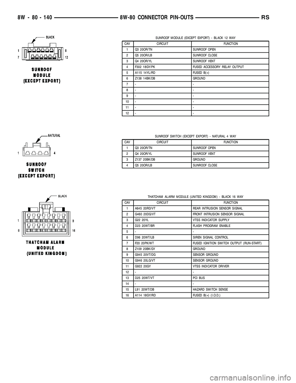
SUNROOF MODULE (EXCEPT EXPORT) - BLACK 12 WAY
CAV CIRCUIT FUNCTION
1 Q3 20OR/TN SUNROOF OPEN
2 Q5 20OR/LB SUNROOF CLOSE
3 Q4 20OR/YL SUNROOF VENT
4 F302 18GY/PK FUSED ACCESSORY RELAY OUTPUT
5 A115 14YL/RD FUSED B(+)
6 Z138 14BK/DB GROUND
7- -
8- -
9- -
10 - -
11 - -
12 - -
SUNROOF SWITCH (EXCEPT EXPORT) - NATURAL 4 WAY
CAV CIRCUIT FUNCTION
1 Q3 20OR/TN SUNROOF OPEN
2 Q4 20OR/YL SUNROOF VENT
3 Z137 20BK/DB GROUND
4 Q5 20OR/LB SUNROOF CLOSE
THATCHAM ALARM MODULE (UNITED KINGDOM) - BLACK 16 WAY
CAV CIRCUIT FUNCTION
1 A645 20RD/VT REAR INTRUSION SENSOR SIGNAL
2 G460 20DG/VT FRONT INTRUSION SENSOR SIGNAL
3 G22 20YL VTSS INDICATOR SUPPLY
4 D23 20WT/BR FLASH PROGRAM ENABLE
5- -
6 D96 20WT/LB SIREN SIGNAL CONTROL
7 F20 20PK/WT FUSED IGNITION SWITCH OUTPUT (RUN-START)
8 Z109 20BK/GY GROUND
9 G945 20VT/DG SENSOR GROUND
10 G946 20LG/VT SENSOR GROUND
11 G922 20GY VTSS INDICATOR DRIVER
12 - -
13 D25 20WT/VT PCI BUS
14 - -
15 L91 20WT/DB HAZARD SWITCH SENSE
16 A114 18GY/RD FUSED B(+) (I.O.D.)
8W - 80 - 140 8W-80 CONNECTOR PIN-OUTSRS
Page 1110 of 2339

THROTTLE POSITION SENSOR (GAS) - GRAY 3 WAY
CAV CIRCUIT FUNCTION
1 K900 18DB/DG SENSOR GROUND
2 K22 18BR/OR TP SIGNAL
3 F855 20PK/YL 5 VOLT SUPPLY
TRACTION CONTROL SWITCH - BLACK 2 WAY
CAV CIRCUIT FUNCTION
1 B27 20DG/WT TRACTION CONTROL SWITCH SENSE
2 Z427 20BK/WT GROUND
TRAILER TOW CONNECTOR (EXCEPT EXPORT)-4WAY
CAV CIRCUIT FUNCTION
1 L62 18LG RIGHT REAR TURN SIGNAL DRIVER
2 Z362 18WT GROUND
3 L77 18BR FUSED PARK LAMP RELAY OUTPUT (LEFT)
4 L63 18YL LEFT REAR TURN SIGNAL DRIVER
TRANSMISSION CONTROL MODULE (DIESEL) - BLACK
CAV CIRCUIT FUNCTION
1 T1 18DG/LB TRS T1 SENSE
2- -
3 T3 18DG/DB TRS T3 SENSE
4- -
5- -
6 K24 20BR/LB CRANKSHAFT POSITION SENSOR SIGNAL NO.2
7 D15 20DG/YL SCI TRANSMIT (TCM)
8 T751 20YL FUSED IGNITION SWITCH OUTPUT (START)
9 T9 18DG/TN OVERDRIVE PRESSURE SWITCH SENSE
10 T10 20DG/LG TORQUE MANAGEMENT REQUEST SENSE
11 F1 18PK/WT FCM OUTPUT (UNLOCK-RUN-START)
12 K23 20BR/OR ACCELERATOR PEDAL POSITION SENSOR SIGNAL
NO.2
13 T13 18DG/VT SPEED SENSOR GROUND
14 T14 18DG/BR OUTPUT SPEED SENSOR SIGNAL
15 T15 18YL/BR TRANSMISSION CONTROL RELAY CONTROL
16 T16 18YL/OR TRANSMISSION CONTROL RELAY OUTPUT
17 T16 18YL/OR TRANSMISSION CONTROL RELAY OUTPUT
18 - -
19 T19 18YL/DB 2-4 SOLENOID CONTROL
20 T20 18DG/WT L/R SOLENOID CONTROL
21 - -
22 - -
RS8W-80 CONNECTOR PIN-OUTS8W - 80 - 141
Page 1113 of 2339
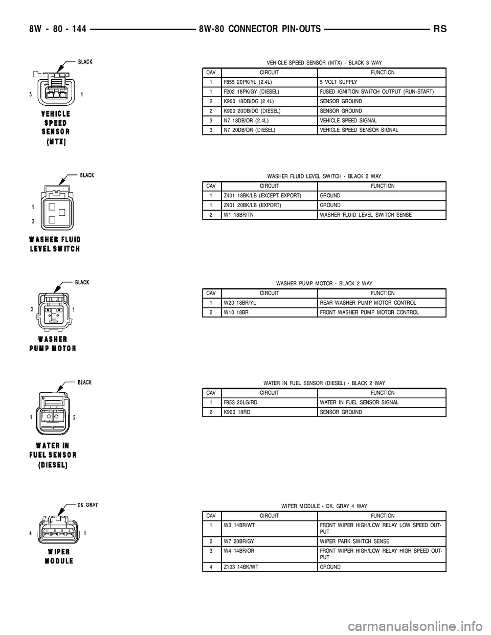
VEHICLE SPEED SENSOR (MTX) - BLACK 3 WAY
CAV CIRCUIT FUNCTION
1 F855 20PK/YL (2.4L) 5 VOLT SUPPLY
1 F202 18PK/GY (DIESEL) FUSED IGNITION SWITCH OUTPUT (RUN-START)
2 K900 18DB/DG (2.4L) SENSOR GROUND
2 K900 20DB/DG (DIESEL) SENSOR GROUND
3 N7 18DB/OR (2.4L) VEHICLE SPEED SIGNAL
3 N7 20DB/OR (DIESEL) VEHICLE SPEED SENSOR SIGNAL
WASHER FLUID LEVEL SWITCH - BLACK 2 WAY
CAV CIRCUIT FUNCTION
1 Z401 18BK/LB (EXCEPT EXPORT) GROUND
1 Z401 20BK/LB (EXPORT) GROUND
2 W1 18BR/TN WASHER FLUID LEVEL SWITCH SENSE
WASHER PUMP MOTOR - BLACK 2 WAY
CAV CIRCUIT FUNCTION
1 W20 18BR/YL REAR WASHER PUMP MOTOR CONTROL
2 W10 18BR FRONT WASHER PUMP MOTOR CONTROL
WATER IN FUEL SENSOR (DIESEL) - BLACK 2 WAY
CAV CIRCUIT FUNCTION
1 F853 20LG/RD WATER IN FUEL SENSOR SIGNAL
2 K900 18RD SENSOR GROUND
WIPER MODULE - DK. GRAY 4 WAY
CAV CIRCUIT FUNCTION
1 W3 14BR/WT FRONT WIPER HIGH/LOW RELAY LOW SPEED OUT-
PUT
2 W7 20BR/GY WIPER PARK SWITCH SENSE
3 W4 14BR/OR FRONT WIPER HIGH/LOW RELAY HIGH SPEED OUT-
PUT
4 Z103 14BK/WT GROUND
8W - 80 - 144 8W-80 CONNECTOR PIN-OUTSRS
Page 1119 of 2339
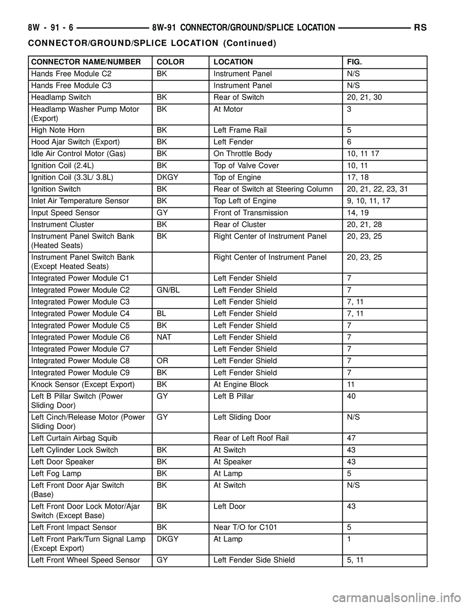
CONNECTOR NAME/NUMBER COLOR LOCATION FIG.
Hands Free Module C2 BK Instrument Panel N/S
Hands Free Module C3 Instrument Panel N/S
Headlamp Switch BK Rear of Switch 20, 21, 30
Headlamp Washer Pump Motor
(Export)BK At Motor 3
High Note Horn BK Left Frame Rail 5
Hood Ajar Switch (Export) BK Left Fender 6
Idle Air Control Motor (Gas) BK On Throttle Body 10, 11 17
Ignition Coil (2.4L) BK Top of Valve Cover 10, 11
Ignition Coil (3.3L/ 3.8L) DKGY Top of Engine 17, 18
Ignition Switch BK Rear of Switch at Steering Column 20, 21, 22, 23, 31
Inlet Air Temperature Sensor BK Top Left of Engine 9, 10, 11, 17
Input Speed Sensor GY Front of Transmission 14, 19
Instrument Cluster BK Rear of Cluster 20, 21, 28
Instrument Panel Switch Bank
(Heated Seats)BK Right Center of Instrument Panel 20, 23, 25
Instrument Panel Switch Bank
(Except Heated Seats)Right Center of Instrument Panel 20, 23, 25
Integrated Power Module C1 Left Fender Shield 7
Integrated Power Module C2 GN/BL Left Fender Shield 7
Integrated Power Module C3 Left Fender Shield 7, 11
Integrated Power Module C4 BL Left Fender Shield 7, 11
Integrated Power Module C5 BK Left Fender Shield 7
Integrated Power Module C6 NAT Left Fender Shield 7
Integrated Power Module C7 Left Fender Shield 7
Integrated Power Module C8 OR Left Fender Shield 7
Integrated Power Module C9 BK Left Fender Shield 7
Knock Sensor (Except Export) BK At Engine Block 11
Left B Pillar Switch (Power
Sliding Door)GY Left B Pillar 40
Left Cinch/Release Motor (Power
Sliding Door)GY Left Sliding Door N/S
Left Curtain Airbag Squib Rear of Left Roof Rail 47
Left Cylinder Lock Switch BK At Switch 43
Left Door Speaker BK At Speaker 43
Left Fog Lamp BK At Lamp 5
Left Front Door Ajar Switch
(Base)BK At Switch N/S
Left Front Door Lock Motor/Ajar
Switch (Except Base)BK Left Door 43
Left Front Impact Sensor BK Near T/O for C101 5
Left Front Park/Turn Signal Lamp
(Except Export)DKGY At Lamp 1
Left Front Wheel Speed Sensor GY Left Fender Side Shield 5, 11
8W - 91 - 6 8W-91 CONNECTOR/GROUND/SPLICE LOCATIONRS
CONNECTOR/GROUND/SPLICE LOCATION (Continued)
Page 1176 of 2339

(5) Connect the negative and positive battery
cables.
(6) Using a scan tool, check for any stored diagnos-
tic trouble codes. Ensure that all vehicle options are
operational.
IOD FUSE
DESCRIPTION
All vehicles are equipped with an Ignition-Off
Draw (IOD) fuse that is removed from its normal
cavity in the Integrated Power Module (IPM) when
the vehicle is shipped from the factory. Dealer per-
sonnel are to remove the IOD fuse from the storage
location and install it into the IPM fuse cavity
marked IOD as part of the preparation procedures
performed just prior to new vehicle delivery.
The IOD fuse is a 20 ampere blade-type mini fuse
and, when removed, it is stored in a fuse cavity adja-
cent to the washer fuse within the IPM.
OPERATION
The term ignition-off draw (IOD) identifies a nor-
mal condition where power is being drained from the
battery with the ignition switch in the Off position.
The IOD fuse feeds the memory and sleep mode func-
tions for some of the electronic modules in the vehicle
as well as various other accessories that require bat-
tery current when the ignition switch is in the Off
position, including the clock. The only reason the
IOD fuse is removed is to reduce the normal IOD of
the vehicle electrical system during new vehicle
transportation and pre-delivery storage to reduce
battery depletion, while still allowing vehicle opera-
tion so that the vehicle can be loaded, unloaded and
moved as needed by both vehicle transportation com-
pany and dealer personnel.
The IOD fuse is removed from the Integrated
Power Module (IPM) fuse cavity when the vehicle is
shipped from the assembly plant. Dealer personnel
must install the IOD fuse when the vehicle is being
prepared for delivery in order to restore full electrical
system operation. Once the vehicle is prepared for
delivery, the IOD function of this fuse becomes trans-
parent and the fuse that has been assigned the IOD
designation becomes only another Fused B(+) circuit
fuse. The IOD fuse serves no useful purpose to the
dealer technician in the service or diagnosis of any
vehicle system or condition, other than the same pur-
pose as that of any other standard circuit protection
device.
The IOD fuse can be used by the vehicle owner as
a convenient means of reducing battery depletion
when a vehicle is to be stored for periods not to
exceed approximately thirty days. However, it mustbe remembered that removing the IOD fuse will not
eliminate IOD, but only reduce this normal condition.
If a vehicle will be stored for more than thirty days,
the battery negative cable should be disconnected to
eliminate normal IOD; and, the battery should be
tested and recharged at regular intervals during the
vehicle storage period to prevent the battery from
becoming discharged or damaged.
POWER OUTLET
DESCRIPTION
Two power outlets are installed in the instrument
panel center lower bezel. Two additional power out-
lets are incorporated into the left rear C-pillar and
the center console (if equipped). The power outlets
bases are secured by a snap fit. A hinged plug flips
closed to conceal and protect the power outlet base
when not in use.
OPERATION
The power outlet base or receptacle shell is con-
nected to ground, and an insulated contact in the
bottom of the shell is connected to battery current.
The power outlet on the instrument panel marked
with a battery receives battery voltage from a fuse in
the Integrated Power Module (IPM) at all times. The
other power outlet on the instrument panel marked
with a key receives battery voltage only when the
key is in the on position.
The power outlet located in the center console
receives battery voltage all the time when positioned
between thefront seatsand key-on voltage when
positioned between therear seats. The power outlet
located on the C-pillar receives battery voltage only
when the key is in the ON position.
DIAGNOSIS AND TESTING
DIAGNOSIS & TESTING - POWER OUTLET
WARNING: ON VEHICLES EQUIPPED WITH AIR-
BAGS, REFER TO RESTRAINTS BEFORE ATTEMPT-
ING ANY STEERING WHEEL, STEERING COLUMN,
SEAT OR INSTRUMENT PANEL COMPONENT DIAG-
NOSIS OR SERVICE. FAILURE TO TAKE THE
PROPER PRECAUTIONS COULD RESULT IN ACCI-
DENTAL AIRBAG DEPLOYMENT AND POSSIBLE
PERSONAL INJURY.
(1) Check the fused B(+) fuse in the Integrated
Power Module (IPM). If OK, go to Step 2. If not OK,
repair the shorted circuit or component as required
and replace the faulty fuse.
RS8W-97 POWER DISTRIBUTION SYSTEM8W-97-3
INTEGRATED POWER MODULE (Continued)
Page 1181 of 2339
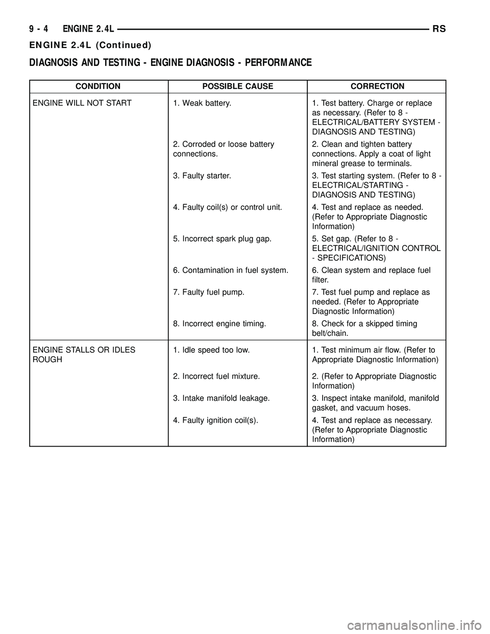
DIAGNOSIS AND TESTING - ENGINE DIAGNOSIS - PERFORMANCE
CONDITION POSSIBLE CAUSE CORRECTION
ENGINE WILL NOT START 1. Weak battery. 1. Test battery. Charge or replace
as necessary. (Refer to 8 -
ELECTRICAL/BATTERY SYSTEM -
DIAGNOSIS AND TESTING)
2. Corroded or loose battery
connections.2. Clean and tighten battery
connections. Apply a coat of light
mineral grease to terminals.
3. Faulty starter. 3. Test starting system. (Refer to 8 -
ELECTRICAL/STARTING -
DIAGNOSIS AND TESTING)
4. Faulty coil(s) or control unit. 4. Test and replace as needed.
(Refer to Appropriate Diagnostic
Information)
5. Incorrect spark plug gap. 5. Set gap. (Refer to 8 -
ELECTRICAL/IGNITION CONTROL
- SPECIFICATIONS)
6. Contamination in fuel system. 6. Clean system and replace fuel
filter.
7. Faulty fuel pump. 7. Test fuel pump and replace as
needed. (Refer to Appropriate
Diagnostic Information)
8. Incorrect engine timing. 8. Check for a skipped timing
belt/chain.
ENGINE STALLS OR IDLES
ROUGH1. Idle speed too low. 1. Test minimum air flow. (Refer to
Appropriate Diagnostic Information)
2. Incorrect fuel mixture. 2. (Refer to Appropriate Diagnostic
Information)
3. Intake manifold leakage. 3. Inspect intake manifold, manifold
gasket, and vacuum hoses.
4. Faulty ignition coil(s). 4. Test and replace as necessary.
(Refer to Appropriate Diagnostic
Information)
9 - 4 ENGINE 2.4LRS
ENGINE 2.4L (Continued)
Page 1182 of 2339
CONDITION POSSIBLE CAUSE CORRECTION
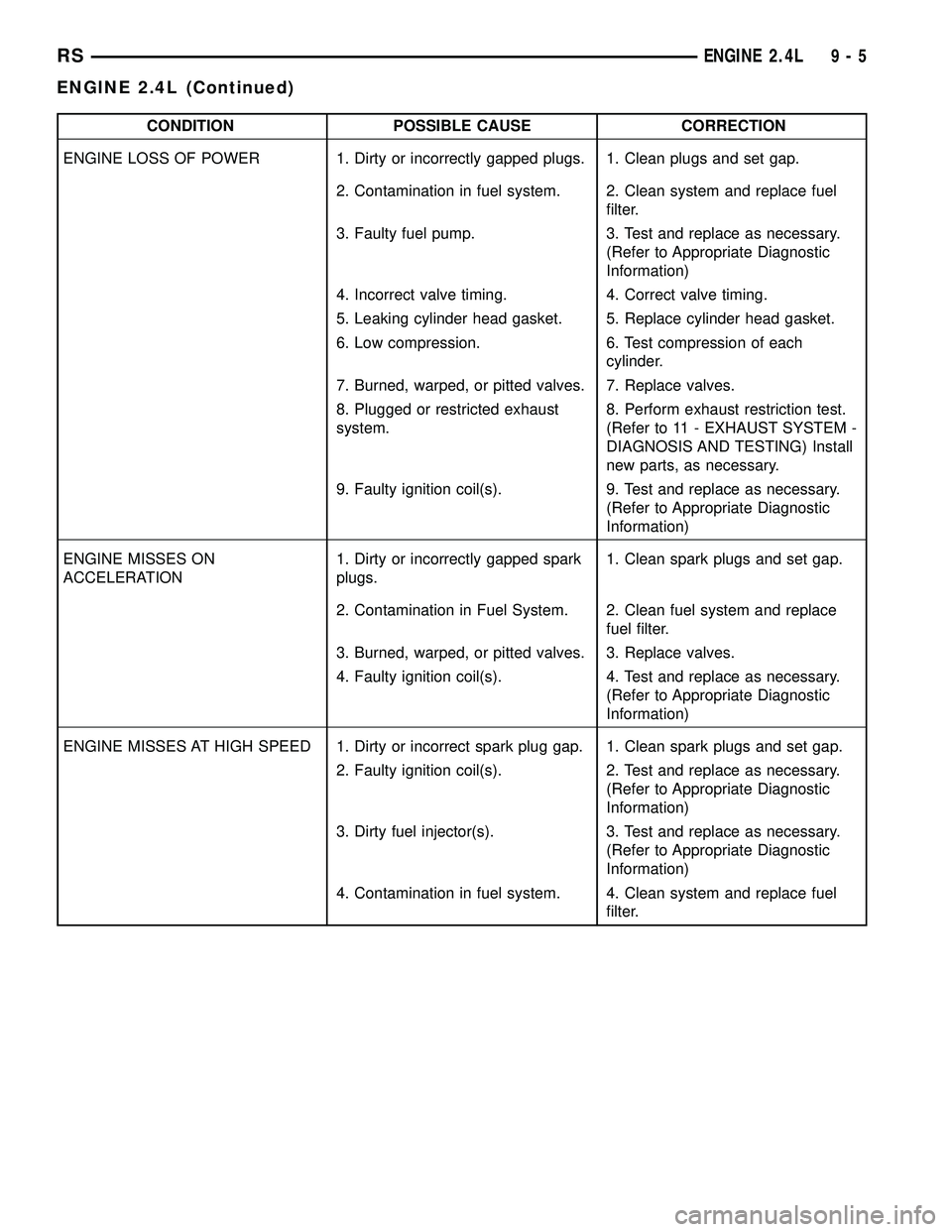
ENGINE LOSS OF POWER 1. Dirty or incorrectly gapped plugs. 1. Clean plugs and set gap.
2. Contamination in fuel system. 2. Clean system and replace fuel
filter.
3. Faulty fuel pump. 3. Test and replace as necessary.
(Refer to Appropriate Diagnostic
Information)
4. Incorrect valve timing. 4. Correct valve timing.
5. Leaking cylinder head gasket. 5. Replace cylinder head gasket.
6. Low compression. 6. Test compression of each
cylinder.
7. Burned, warped, or pitted valves. 7. Replace valves.
8. Plugged or restricted exhaust
system.8. Perform exhaust restriction test.
(Refer to 11 - EXHAUST SYSTEM -
DIAGNOSIS AND TESTING) Install
new parts, as necessary.
9. Faulty ignition coil(s). 9. Test and replace as necessary.
(Refer to Appropriate Diagnostic
Information)
ENGINE MISSES ON
ACCELERATION1. Dirty or incorrectly gapped spark
plugs.1. Clean spark plugs and set gap.
2. Contamination in Fuel System. 2. Clean fuel system and replace
fuel filter.
3. Burned, warped, or pitted valves. 3. Replace valves.
4. Faulty ignition coil(s). 4. Test and replace as necessary.
(Refer to Appropriate Diagnostic
Information)
ENGINE MISSES AT HIGH SPEED 1. Dirty or incorrect spark plug gap. 1. Clean spark plugs and set gap.
2. Faulty ignition coil(s). 2. Test and replace as necessary.
(Refer to Appropriate Diagnostic
Information)
3. Dirty fuel injector(s). 3. Test and replace as necessary.
(Refer to Appropriate Diagnostic
Information)
4. Contamination in fuel system. 4. Clean system and replace fuel
filter.
RSENGINE 2.4L9-5
ENGINE 2.4L (Continued)
Page 1203 of 2339
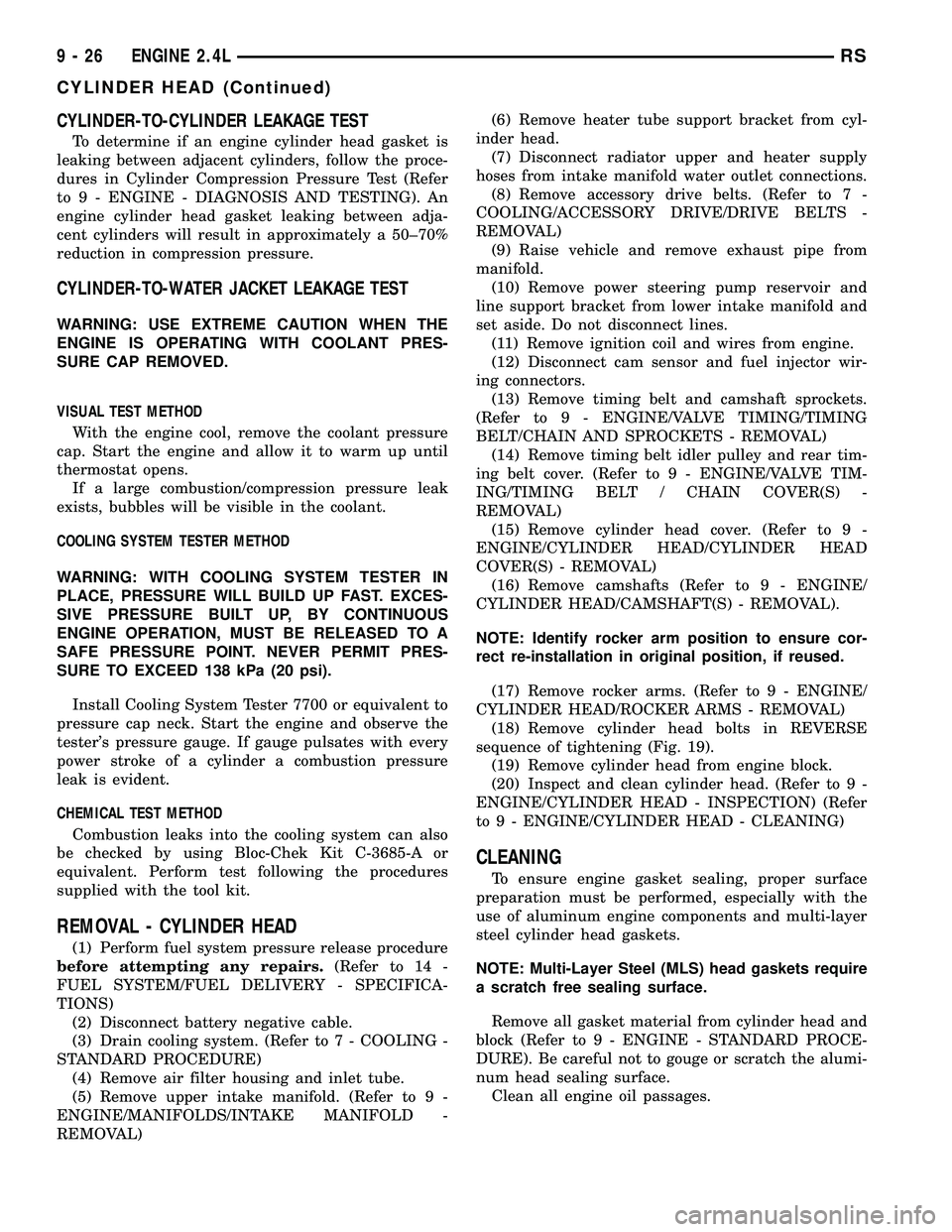
CYLINDER-TO-CYLINDER LEAKAGE TEST
To determine if an engine cylinder head gasket is
leaking between adjacent cylinders, follow the proce-
dures in Cylinder Compression Pressure Test (Refer
to 9 - ENGINE - DIAGNOSIS AND TESTING). An
engine cylinder head gasket leaking between adja-
cent cylinders will result in approximately a 50±70%
reduction in compression pressure.
CYLINDER-TO-WATER JACKET LEAKAGE TEST
WARNING: USE EXTREME CAUTION WHEN THE
ENGINE IS OPERATING WITH COOLANT PRES-
SURE CAP REMOVED.
VISUAL TEST METHOD
With the engine cool, remove the coolant pressure
cap. Start the engine and allow it to warm up until
thermostat opens.
If a large combustion/compression pressure leak
exists, bubbles will be visible in the coolant.
COOLING SYSTEM TESTER METHOD
WARNING: WITH COOLING SYSTEM TESTER IN
PLACE, PRESSURE WILL BUILD UP FAST. EXCES-
SIVE PRESSURE BUILT UP, BY CONTINUOUS
ENGINE OPERATION, MUST BE RELEASED TO A
SAFE PRESSURE POINT. NEVER PERMIT PRES-
SURE TO EXCEED 138 kPa (20 psi).
Install Cooling System Tester 7700 or equivalent to
pressure cap neck. Start the engine and observe the
tester's pressure gauge. If gauge pulsates with every
power stroke of a cylinder a combustion pressure
leak is evident.
CHEMICAL TEST METHOD
Combustion leaks into the cooling system can also
be checked by using Bloc-Chek Kit C-3685-A or
equivalent. Perform test following the procedures
supplied with the tool kit.
REMOVAL - CYLINDER HEAD
(1) Perform fuel system pressure release procedure
before attempting any repairs.(Refer to 14 -
FUEL SYSTEM/FUEL DELIVERY - SPECIFICA-
TIONS)
(2) Disconnect battery negative cable.
(3) Drain cooling system. (Refer to 7 - COOLING -
STANDARD PROCEDURE)
(4) Remove air filter housing and inlet tube.
(5) Remove upper intake manifold. (Refer to 9 -
ENGINE/MANIFOLDS/INTAKE MANIFOLD -
REMOVAL)(6) Remove heater tube support bracket from cyl-
inder head.
(7) Disconnect radiator upper and heater supply
hoses from intake manifold water outlet connections.
(8) Remove accessory drive belts. (Refer to 7 -
COOLING/ACCESSORY DRIVE/DRIVE BELTS -
REMOVAL)
(9) Raise vehicle and remove exhaust pipe from
manifold.
(10) Remove power steering pump reservoir and
line support bracket from lower intake manifold and
set aside. Do not disconnect lines.
(11) Remove ignition coil and wires from engine.
(12) Disconnect cam sensor and fuel injector wir-
ing connectors.
(13) Remove timing belt and camshaft sprockets.
(Refer to 9 - ENGINE/VALVE TIMING/TIMING
BELT/CHAIN AND SPROCKETS - REMOVAL)
(14) Remove timing belt idler pulley and rear tim-
ing belt cover. (Refer to 9 - ENGINE/VALVE TIM-
ING/TIMING BELT / CHAIN COVER(S) -
REMOVAL)
(15) Remove cylinder head cover. (Refer to 9 -
ENGINE/CYLINDER HEAD/CYLINDER HEAD
COVER(S) - REMOVAL)
(16) Remove camshafts (Refer to 9 - ENGINE/
CYLINDER HEAD/CAMSHAFT(S) - REMOVAL).
NOTE: Identify rocker arm position to ensure cor-
rect re-installation in original position, if reused.
(17) Remove rocker arms. (Refer to 9 - ENGINE/
CYLINDER HEAD/ROCKER ARMS - REMOVAL)
(18) Remove cylinder head bolts in REVERSE
sequence of tightening (Fig. 19).
(19) Remove cylinder head from engine block.
(20) Inspect and clean cylinder head. (Refer to 9 -
ENGINE/CYLINDER HEAD - INSPECTION) (Refer
to 9 - ENGINE/CYLINDER HEAD - CLEANING)
CLEANING
To ensure engine gasket sealing, proper surface
preparation must be performed, especially with the
use of aluminum engine components and multi-layer
steel cylinder head gaskets.
NOTE: Multi-Layer Steel (MLS) head gaskets require
a scratch free sealing surface.
Remove all gasket material from cylinder head and
block (Refer to 9 - ENGINE - STANDARD PROCE-
DURE). Be careful not to gouge or scratch the alumi-
num head sealing surface.
Clean all engine oil passages.
9 - 26 ENGINE 2.4LRS
CYLINDER HEAD (Continued)