2005 CHRYSLER CARAVAN steering wheel
[x] Cancel search: steering wheelPage 2200 of 2339
(12) Gently flex the recirculation air door far down
enough to remove the blower motor and wheel from
the HVAC housing.
(13) Remove the blower motor and wheel from the
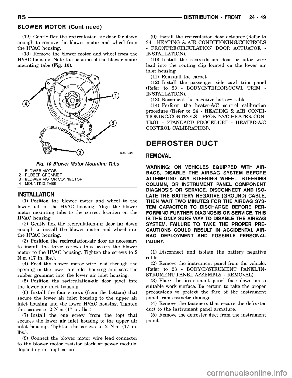
HVAC housing. Note the position of the blower motor
mounting tabs (Fig. 10).
INSTALLATION
(1) Position the blower motor and wheel to the
lower half of the HVAC housing. Align the blower
motor mounting tabs to the correct location on the
HVAC housing.
(2) Gently flex the recirculation-air door far down
enough to install the blower motor and wheel into
the HVAC housing.
(3) Position the recirculation-air door as necessary
to install the three screws that secure the blower
motor to the HVAC housing. Tighten the screws to 2
N´m (17 in. lbs.).
(4) Feed the blower motor wire lead through the
opening in the lower air inlet housing and seat the
rubber grommet into the lower air inlet housing.
(5) Position the recirculation-air door pivot into
the lower air inlet housing.
(6) Install the four screws (from the bottom) that
secure the lower air inlet housing to the upper air
inlet housing and the lower HVAC housing. Tighten
the screws to 2 N´m (17 in. lbs.).
(7) Install the one screw (from the top) that
secures the lower air inlet housing to the upper air
inlet housing. Tighten the screws to 2 N´m (17 in.
lbs.).
(8) Connect the blower motor wire lead connector
to the blower motor resistor block or power module,
depending on application.(9) Install the recirculation door actuator (Refer to
24 - HEATING & AIR CONDITIONING/CONTROLS
- FRONT/RECIRCULATION DOOR ACTUATOR -
INSTALLATION).
(10) Install the recirculation door actuator wire
lead into the routing clip located on the lower air
inlet housing.
(11) Reinstall the carpet.
(12) Install the passenger side cowl trim panel
(Refer to 23 - BODY/INTERIOR/COWL TRIM -
INSTALLATION).
(13) Reconnect the negative battery cable.
(14) Perform the heater-A/C control calibration
procedure (Refer to 24 - HEATING & AIR CONDI-
TIONING/CONTROLS - FRONT/A/C-HEATER CON-
TROL - STANDARD PROCEDURE - HEATER-A/C
CONTROL CALIBRATION).
DEFROSTER DUCT
REMOVAL
WARNING: ON VEHICLES EQUIPPED WITH AIR-
BAGS, DISABLE THE AIRBAG SYSTEM BEFORE
ATTEMPTING ANY STEERING WHEEL, STEERING
COLUMN, OR INSTRUMENT PANEL COMPONENT
DIAGNOSIS OR SERVICE. DISCONNECT AND ISO-
LATE THE BATTERY NEGATIVE (GROUND) CABLE,
THEN WAIT TWO MINUTES FOR THE AIRBAG SYS-
TEM CAPACITOR TO DISCHARGE BEFORE PER-
FORMING FURTHER DIAGNOSIS OR SERVICE. THIS
IS THE ONLY SURE WAY TO DISABLE THE AIRBAG
SYSTEM. FAILURE TO TAKE THE PROPER PRE-
CAUTIONS COULD RESULT IN ACCIDENTAL AIR-
BAG DEPLOYMENT AND POSSIBLE PERSONAL
INJURY.
(1) Disconnect and isolate the battery negative
cable.
(2) Remove the instrument panel from the vehicle.
(Refer to 23 - BODY/INSTRUMENT PANEL/IN-
STRUMENT PANEL ASSEMBLY - REMOVAL).
(3) Place the instrument panel face down on a
suitable work surface. Be certain to take the proper
precautions to protect the face of the instrument
panel from cosmetic damage.
(4) Remove the fasteners that secure the defroster
duct to the instrument panel armature.
(5) Remove the defroster duct from the instrument
panel.Fig. 10 Blower Motor Mounting Tabs
1 - BLOWER MOTOR
2 - RUBBER GROMMET
3 - BLOWER MOTOR CONNECTOR
4 - MOUNTING TABS
RSDISTRIBUTION - FRONT24-49
BLOWER MOTOR (Continued)
Page 2201 of 2339
INSTALLATION
WARNING: ON VEHICLES EQUIPPED WITH AIR-
BAGS, DISABLE THE AIRBAG SYSTEM BEFORE
ATTEMPTING ANY STEERING WHEEL, STEERING
COLUMN, OR INSTRUMENT PANEL COMPONENT
DIAGNOSIS OR SERVICE. DISCONNECT AND ISO-
LATE THE BATTERY NEGATIVE (GROUND) CABLE,
THEN WAIT TWO MINUTES FOR THE AIRBAG SYS-
TEM CAPACITOR TO DISCHARGE BEFORE PER-
FORMING FURTHER DIAGNOSIS OR SERVICE. THIS
IS THE ONLY SURE WAY TO DISABLE THE AIRBAG
SYSTEM. FAILURE TO TAKE THE PROPER PRECAU-
TIONS COULD RESULT IN ACCIDENTAL AIRBAG
DEPLOYMENT AND POSSIBLE PERSONAL INJURY.
(1) Position the defroster duct to the instrument
panel.
(2) Install the fasteners that secure the defroster
duct to the instrument panel armature.
(3) Reinstall the instrument panel in the vehicle.
(Refer to 23 - BODY/INSTRUMENT PANEL/INSTRU-
MENT PANEL ASSEMBLY - INSTALLATION).
(4) Reconnect the battery negative cable.
FLOOR DISTRIBUTION DUCTS
REMOVAL
(1) Roll back the carpet on the front floor from
under the instrument panel toward the rear of the
vehicle (Refer to 23 - BODY/INTERIOR/CARPETS
AND FLOOR MATS - REMOVAL).
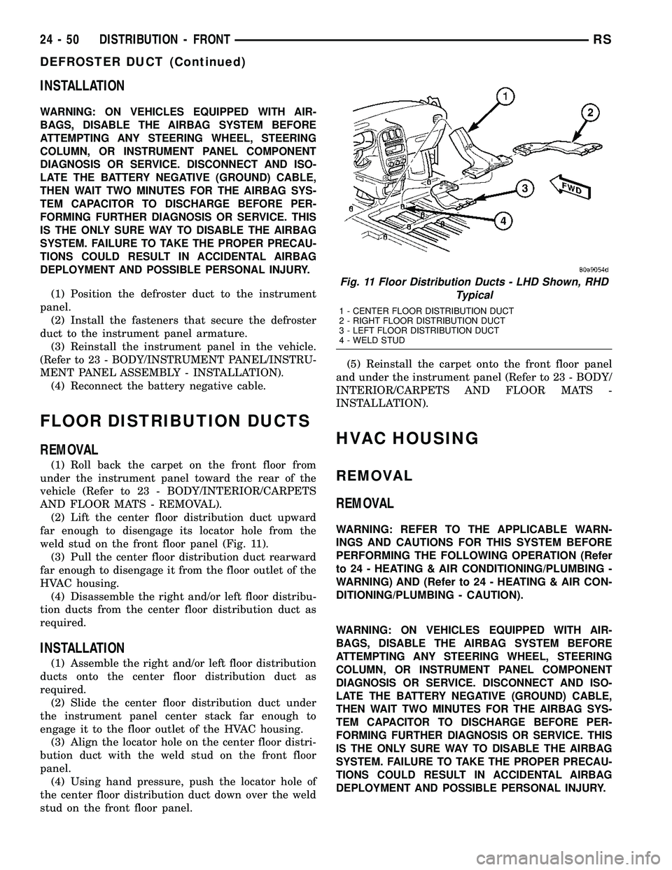
(2) Lift the center floor distribution duct upward
far enough to disengage its locator hole from the
weld stud on the front floor panel (Fig. 11).
(3) Pull the center floor distribution duct rearward
far enough to disengage it from the floor outlet of the
HVAC housing.
(4) Disassemble the right and/or left floor distribu-
tion ducts from the center floor distribution duct as
required.
INSTALLATION
(1) Assemble the right and/or left floor distribution
ducts onto the center floor distribution duct as
required.
(2) Slide the center floor distribution duct under
the instrument panel center stack far enough to
engage it to the floor outlet of the HVAC housing.
(3) Align the locator hole on the center floor distri-
bution duct with the weld stud on the front floor
panel.
(4) Using hand pressure, push the locator hole of
the center floor distribution duct down over the weld
stud on the front floor panel.(5) Reinstall the carpet onto the front floor panel
and under the instrument panel (Refer to 23 - BODY/
INTERIOR/CARPETS AND FLOOR MATS -
INSTALLATION).
HVAC HOUSING
REMOVAL
REMOVAL
WARNING: REFER TO THE APPLICABLE WARN-
INGS AND CAUTIONS FOR THIS SYSTEM BEFORE
PERFORMING THE FOLLOWING OPERATION (Refer
to 24 - HEATING & AIR CONDITIONING/PLUMBING -
WARNING) AND (Refer to 24 - HEATING & AIR CON-
DITIONING/PLUMBING - CAUTION).
WARNING: ON VEHICLES EQUIPPED WITH AIR-
BAGS, DISABLE THE AIRBAG SYSTEM BEFORE
ATTEMPTING ANY STEERING WHEEL, STEERING
COLUMN, OR INSTRUMENT PANEL COMPONENT
DIAGNOSIS OR SERVICE. DISCONNECT AND ISO-
LATE THE BATTERY NEGATIVE (GROUND) CABLE,
THEN WAIT TWO MINUTES FOR THE AIRBAG SYS-
TEM CAPACITOR TO DISCHARGE BEFORE PER-
FORMING FURTHER DIAGNOSIS OR SERVICE. THIS
IS THE ONLY SURE WAY TO DISABLE THE AIRBAG
SYSTEM. FAILURE TO TAKE THE PROPER PRECAU-
TIONS COULD RESULT IN ACCIDENTAL AIRBAG
DEPLOYMENT AND POSSIBLE PERSONAL INJURY.
Fig. 11 Floor Distribution Ducts - LHD Shown, RHD
Typical
1 - CENTER FLOOR DISTRIBUTION DUCT
2 - RIGHT FLOOR DISTRIBUTION DUCT
3 - LEFT FLOOR DISTRIBUTION DUCT
4 - WELD STUD
24 - 50 DISTRIBUTION - FRONTRS
DEFROSTER DUCT (Continued)
Page 2205 of 2339
(7) Reconnect the heater hoses to the heater core
tubes (Refer to 24 - HEATING & AIR CONDITION-
ING/PLUMBING - FRONT/HEATER HOSE -
INSTALLATION).
(8) Reconnect the suction line and liquid line to
the expansion valve (Refer to 24 - HEATING & AIR
CONDITIONING/PLUMBING - FRONT/SUCTION
LINE - INSTALLATION) and (Refer to 24 - HEAT-
ING & AIR CONDITIONING/PLUMBING - FRONT/
LIQUID LINE - INSTALLATION).
(9) Install the windshield wiper module (Refer to 8
- ELECTRICAL/WIPERS/WASHERS/WIPER MOD-
ULE - INSTALLATION).
(10) Reconnect the negative battery cable.
(11) Refill the engine cooling system (Refer to 7 -
COOLING - STANDARD PROCEDURE - COOLING
SYSTEM REFILL).
(12) Evacuate the refrigerant system (Refer to 24 -
HEATING & AIR CONDITIONING/PLUMBING -
FRONT/REFRIGERANT - STANDARD PROCE-
DURE - REFRIGERANT SYSTEM EVACUATE).
(13) Charge the refrigerant system (Refer to 24 -
HEATING & AIR CONDITIONING/PLUMBING -
FRONT/REFRIGERANT - STANDARD PROCE-
DURE - REFRIGERANT SYSTEM CHARGE).
INSTRUMENT PANEL
DEMISTER DUCTS
REMOVAL
WARNING: ON VEHICLES EQUIPPED WITH AIR-
BAGS, DISABLE THE AIRBAG SYSTEM BEFORE
ATTEMPTING ANY STEERING WHEEL, STEERING
COLUMN, OR INSTRUMENT PANEL COMPONENT
DIAGNOSIS OR SERVICE. DISCONNECT AND ISO-
LATE THE BATTERY NEGATIVE (GROUND) CABLE,
THEN WAIT TWO MINUTES FOR THE AIRBAG SYS-
TEM CAPACITOR TO DISCHARGE BEFORE PER-
FORMING FURTHER DIAGNOSIS OR SERVICE. THIS
IS THE ONLY SURE WAY TO DISABLE THE AIRBAG
SYSTEM. FAILURE TO TAKE THE PROPER PRE-
CAUTIONS COULD RESULT IN ACCIDENTAL AIR-
BAG DEPLOYMENT AND POSSIBLE PERSONAL
INJURY.(1) Disconnect and isolate the battery negative
cable.
(2) Remove the instrument panel from the vehicle.
(Refer to 23 - BODY/INSTRUMENT PANEL/IN-
STRUMENT PANEL ASSEMBLY - REMOVAL).
(3) Place the instrument panel face down on a
suitable work surface. Be certain to take the proper
precautions to protect the face of the instrument
panel from cosmetic damage.
(4) Remove the fasteners that secure the demister
ducts to the instrument panel armature.
(5) Disengage the demister ducts from the demis-
ter outlets.
(6) Remove the demister ducts from the instru-
ment panel.
INSTALLATION
WARNING: ON VEHICLES EQUIPPED WITH AIR-
BAGS, DISABLE THE AIRBAG SYSTEM BEFORE
ATTEMPTING ANY STEERING WHEEL, STEERING
COLUMN, OR INSTRUMENT PANEL COMPONENT
DIAGNOSIS OR SERVICE. DISCONNECT AND ISO-
LATE THE BATTERY NEGATIVE (GROUND) CABLE,
THEN WAIT TWO MINUTES FOR THE AIRBAG SYS-
TEM CAPACITOR TO DISCHARGE BEFORE PER-
FORMING FURTHER DIAGNOSIS OR SERVICE. THIS
IS THE ONLY SURE WAY TO DISABLE THE AIRBAG
SYSTEM. FAILURE TO TAKE THE PROPER PRE-
CAUTIONS COULD RESULT IN ACCIDENTAL AIR-
BAG DEPLOYMENT AND POSSIBLE PERSONAL
INJURY.
(1) Position the demister ducts to the instrument
panel.
(2) Engage the demister ducts to the demister out-
lets.
(3) Install the fasteners that secure the demister
ducts to the instrument panel armature.
(4) Reinstall the instrument panel into the vehicle.
(Refer to 23 - BODY/INSTRUMENT PANEL/IN-
STRUMENT PANEL ASSEMBLY - INSTALLA-
TION).
(5) Reconnect the battery negative cable.
24 - 54 DISTRIBUTION - FRONTRS
HVAC HOUSING (Continued)
Page 2206 of 2339
INSTRUMENT PANEL DUCTS
REMOVAL
WARNING: ON VEHICLES EQUIPPED WITH AIR-
BAGS, DISABLE THE AIRBAG SYSTEM BEFORE
ATTEMPTING ANY STEERING WHEEL, STEERING
COLUMN, OR INSTRUMENT PANEL COMPONENT
DIAGNOSIS OR SERVICE. DISCONNECT AND ISO-
LATE THE BATTERY NEGATIVE (GROUND) CABLE,
THEN WAIT TWO MINUTES FOR THE AIRBAG SYS-
TEM CAPACITOR TO DISCHARGE BEFORE PER-
FORMING FURTHER DIAGNOSIS OR SERVICE. THIS
IS THE ONLY SURE WAY TO DISABLE THE AIRBAG
SYSTEM. FAILURE TO TAKE THE PROPER PRE-
CAUTIONS COULD RESULT IN ACCIDENTAL AIR-
BAG DEPLOYMENT AND POSSIBLE PERSONAL
INJURY.
(1) Disconnect and isolate the battery negative
cable.
(2) Remove the instrument panel from the vehicle
(Refer to 23 - BODY/INSTRUMENT PANEL/IN-
STRUMENT PANEL ASSEMBLY - REMOVAL).(3) Place the instrument panel face down on a
suitable work surface. Be certain to take the proper
precautions to protect the face of the instrument
panel from cosmetic damage.
(4) Remove the screws that secure the panel ducts
to the instrument panel armature.
(5) Disengage the panel ducts from the panel out-
lets.
(6) Remove the panel ducts from the instrument
panel.
INSTALLATION
(1) Position the panel ducts to the instrument
panel.
(2) Engage the panel ducts to the panel outlets.
(3) Install the screws that secure the panel ducts
to the instrument panel armature.
(4) Reinstall the instrument panel into the vehicle
(Refer to 23 - BODY/INSTRUMENT PANEL/IN-
STRUMENT PANEL ASSEMBLY - INSTALLA-
TION).
(5) Reconnect the battery negative cable.
RSDISTRIBUTION - FRONT24-55
Page 2232 of 2339
REMOVAL
WARNING: ON VEHICLES EQUIPPED WITH AIR-
BAGS, DISABLE THE AIRBAG SYSTEM BEFORE
ATTEMPTING ANY STEERING WHEEL, STEERING
COLUMN, OR INSTRUMENT PANEL COMPONENT
DIAGNOSIS OR SERVICE. DISCONNECT AND ISO-
LATE THE BATTERY NEGATIVE (GROUND) CABLE,
THEN WAIT TWO MINUTES FOR THE AIRBAG SYS-
TEM CAPACITOR TO DISCHARGE BEFORE PER-
FORMING FURTHER DIAGNOSIS OR SERVICE. THIS
IS THE ONLY SURE WAY TO DISABLE THE AIRBAG
SYSTEM. FAILURE TO TAKE THE PROPER PRE-
CAUTIONS COULD RESULT IN ACCIDENTAL AIR-
BAG DEPLOYMENT AND POSSIBLE PERSONAL
INJURY.
(1) Remove the HVAC housing (Refer to 24 -
HEATING & AIR CONDITIONING/DISTRIBUTION/
HVAC HOUSING - REMOVAL).
(2) Disassemble the HVAC housing to access the
evaporator (Refer to 24 - HEATING & AIR CONDI-
TIONING/DISTRIBUTION/HVAC HOUSING - DIS-
ASSEMBLY).
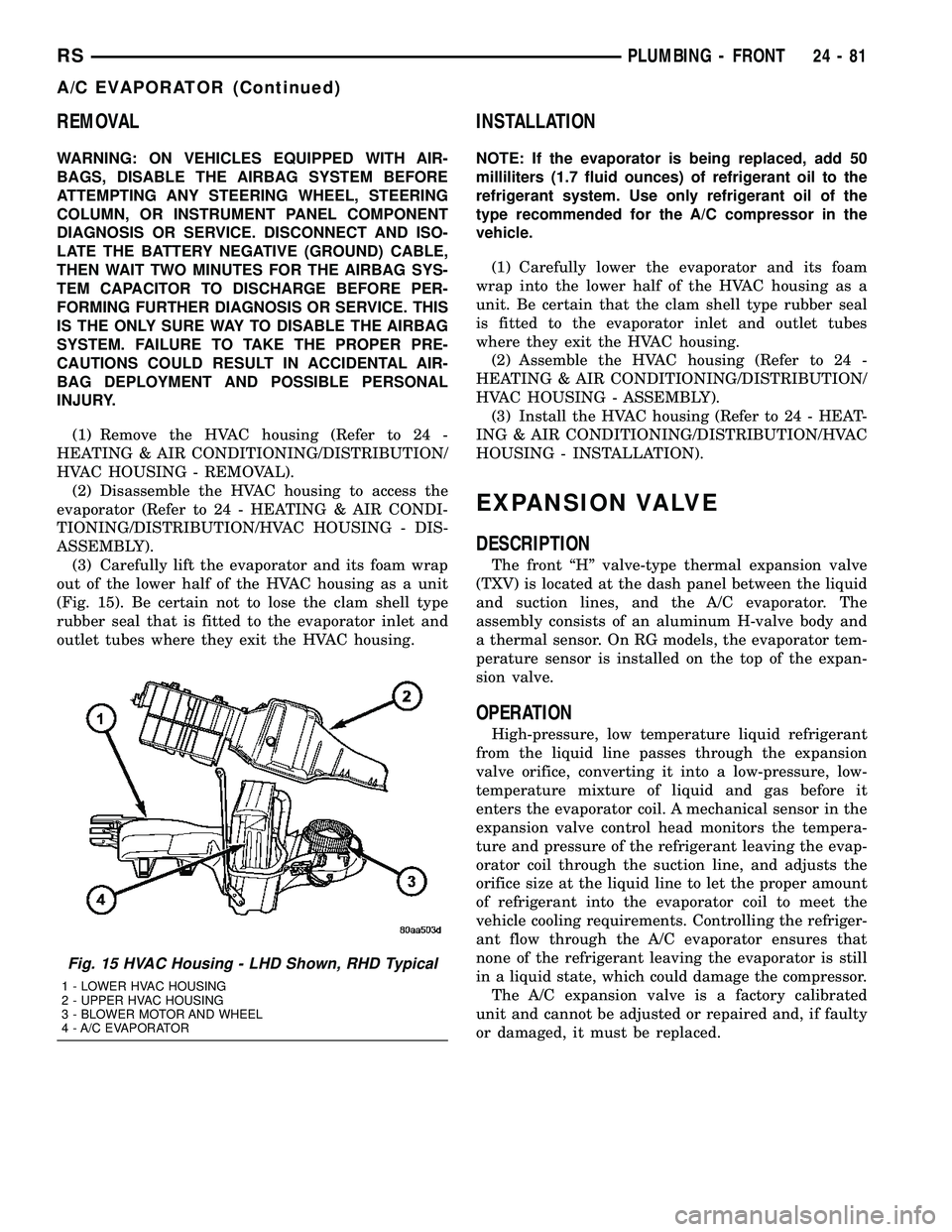
(3) Carefully lift the evaporator and its foam wrap
out of the lower half of the HVAC housing as a unit
(Fig. 15). Be certain not to lose the clam shell type
rubber seal that is fitted to the evaporator inlet and
outlet tubes where they exit the HVAC housing.
INSTALLATION
NOTE: If the evaporator is being replaced, add 50
milliliters (1.7 fluid ounces) of refrigerant oil to the
refrigerant system. Use only refrigerant oil of the
type recommended for the A/C compressor in the
vehicle.
(1) Carefully lower the evaporator and its foam
wrap into the lower half of the HVAC housing as a
unit. Be certain that the clam shell type rubber seal
is fitted to the evaporator inlet and outlet tubes
where they exit the HVAC housing.
(2) Assemble the HVAC housing (Refer to 24 -
HEATING & AIR CONDITIONING/DISTRIBUTION/
HVAC HOUSING - ASSEMBLY).
(3) Install the HVAC housing (Refer to 24 - HEAT-
ING & AIR CONDITIONING/DISTRIBUTION/HVAC
HOUSING - INSTALLATION).
EXPANSION VALVE
DESCRIPTION
The front ªHº valve-type thermal expansion valve
(TXV) is located at the dash panel between the liquid
and suction lines, and the A/C evaporator. The
assembly consists of an aluminum H-valve body and
a thermal sensor. On RG models, the evaporator tem-
perature sensor is installed on the top of the expan-
sion valve.
OPERATION
High-pressure, low temperature liquid refrigerant
from the liquid line passes through the expansion
valve orifice, converting it into a low-pressure, low-
temperature mixture of liquid and gas before it
enters the evaporator coil. A mechanical sensor in the
expansion valve control head monitors the tempera-
ture and pressure of the refrigerant leaving the evap-
orator coil through the suction line, and adjusts the
orifice size at the liquid line to let the proper amount
of refrigerant into the evaporator coil to meet the
vehicle cooling requirements. Controlling the refriger-
ant flow through the A/C evaporator ensures that
none of the refrigerant leaving the evaporator is still
in a liquid state, which could damage the compressor.
The A/C expansion valve is a factory calibrated
unit and cannot be adjusted or repaired and, if faulty
or damaged, it must be replaced.
Fig. 15 HVAC Housing - LHD Shown, RHD Typical
1 - LOWER HVAC HOUSING
2 - UPPER HVAC HOUSING
3 - BLOWER MOTOR AND WHEEL
4 - A/C EVAPORATOR
RSPLUMBING - FRONT24-81
A/C EVAPORATOR (Continued)
Page 2235 of 2339
heater core inlet and outlet ports. Removable heater
core tubes attach to the ports by use of a sealing
plate secured with a screw to the heater core tank.
This removable heater core tube arrangement allows
the heater core to be serviced without removing the
HVAC housing from the vehicle.
OPERATION
Engine coolant is circulated through heater hoses
to the heater core at all times. As the coolant flows
through the heater core, heat removed from the
engine is transferred to the heater core fins and
tubes. Air directed through the heater core picks up
the heat from the heater core fins. The blend door
allows control of the heater output air temperature
by regulating the amount of air that is flowing
through the heater core within the HVAC housing.
The heater core cannot be repaired and, if faulty or
damaged, it must be replaced.
REMOVAL
FRONT HEATER CORE TUBES
WARNING: ON VEHICLES EQUIPPED WITH AIR-
BAGS, DISABLE THE AIRBAG SYSTEM BEFORE
ATTEMPTING ANY STEERING WHEEL, STEERING
COLUMN, OR INSTRUMENT PANEL COMPONENT
DIAGNOSIS OR SERVICE. DISCONNECT AND ISO-
LATE THE BATTERY NEGATIVE (GROUND) CABLE,
THEN WAIT TWO MINUTES FOR THE AIRBAG SYS-
TEM CAPACITOR TO DISCHARGE BEFORE PER-
FORMING FURTHER DIAGNOSIS OR SERVICE. THIS
IS THE ONLY SURE WAY TO DISABLE THE AIRBAG
SYSTEM. FAILURE TO TAKE THE PROPER PRE-
CAUTIONS COULD RESULT IN ACCIDENTAL AIR-
BAG DEPLOYMENT AND POSSIBLE PERSONAL
INJURY.
(1) Drain the engine cooling system (Refer to 7 -
COOLING - STANDARD PROCEDURE - COOLING
SYSTEM DRAIN).
(2) Disconnect and isolate the battery negative
cable.
(3) Disconnect the heater hoses from the heater
core tubes (Refer to 24 - HEATING & AIR CONDI-
TIONING/PLUMBING/HEATER INLET HOSE -
REMOVAL) and (Refer to 24 - HEATING & AIR
CONDITIONING/PLUMBING/HEATER RETURN
HOSE - REMOVAL).(4) Remove the silencer from beneath the driver
side end of the instrument panel.
NOTE: Take the proper precautions to protect the
carpeting below the heater core from spilled engine
coolant and have absorbent toweling readily avail-
able to clean up any spills.
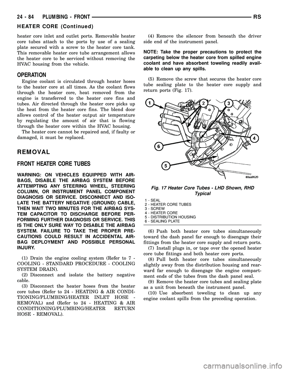
(5) Remove the screw that secures the heater core
tube sealing plate to the heater core supply and
return ports (Fig. 17).
(6) Push both heater core tubes simultaneously
toward the dash panel far enough to disengage their
fittings from the heater core supply and return ports.
(7) Install plugs in, or tape over the opened heater
core tube fittings and both heater core ports.
(8) Pull both heater core tubes simultaneously
slightly away from the distribution housing and rear-
ward far enough to disengage the engine compart-
ment ends of the tubes from the dash panel seal.
(9) Remove the heater core tubes and sealing plate
as a unit from beneath the instrument panel.
(10) Use absorbent toweling to clean up any
engine coolant spills from the preceding operation.
Fig. 17 Heater Core Tubes - LHD Shown, RHD
Typical
1 - SEAL
2 - HEATER CORE TUBES
3 - SCREW
4 - HEATER CORE
5 - DISTRIBUTION HOUSING
6 - SEALING PLATE
24 - 84 PLUMBING - FRONTRS
HEATER CORE (Continued)
Page 2236 of 2339
FRONT HEATER CORE
WARNING: ON VEHICLES EQUIPPED WITH AIR-
BAGS, DISABLE THE AIRBAG SYSTEM BEFORE
ATTEMPTING ANY STEERING WHEEL, STEERING
COLUMN, OR INSTRUMENT PANEL COMPONENT
DIAGNOSIS OR SERVICE. DISCONNECT AND ISO-
LATE THE BATTERY NEGATIVE (GROUND) CABLE,
THEN WAIT TWO MINUTES FOR THE AIRBAG SYS-
TEM CAPACITOR TO DISCHARGE BEFORE PER-
FORMING FURTHER DIAGNOSIS OR SERVICE. THIS
IS THE ONLY SURE WAY TO DISABLE THE AIRBAG
SYSTEM. FAILURE TO TAKE THE PROPER PRE-
CAUTIONS COULD RESULT IN ACCIDENTAL AIR-
BAG DEPLOYMENT AND POSSIBLE PERSONAL
INJURY.
(1) Remove the silencer boot fasteners located
around the base of the lower steering shaft from the
dash panel so that it may be pushed aside.
(2) Remove the brake lamp switch from its mount-
ing bracket (Refer to 8 - ELECTRICAL/LAMPS/
LIGHTING - EXTERIOR/BRAKE LAMP SWITCH -
REMOVAL).
(3) Disconnect the power brake booster input rod
(push rod) from the pin on the brake pedal arm
(Refer to 5 - BRAKES - ABS/HYDRAULIC/ME-
CHANICAL/POWER BRAKE BOOSTER -
REMOVAL).
(4) Remove the heater core tubes (Refer to 24 -
HEATING & AIR CONDITIONING/PLUMBING/
HEATER CORE - REMOVAL).
(5) Remove the two screws that secure the heater
core mounting plate to the distribution housing.
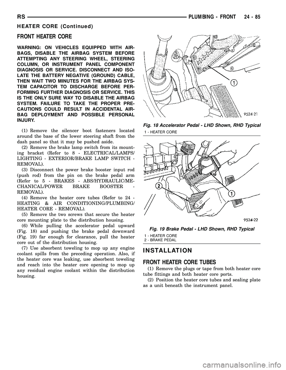
(6) While pulling the accelerator pedal upward
(Fig. 18) and pushing the brake pedal downward
(Fig. 19) far enough for clearance, pull the heater
core out of the distribution housing.
(7) Use absorbent toweling to mop up any engine
coolant spills from the preceding operation. Also, if
the heater core was leaking, use absorbent toweling
and reach into the heater core opening to mop up
any residual engine coolant within the distribution
housing.
INSTALLATION
FRONT HEATER CORE TUBES
(1) Remove the plugs or tape from both heater core
tube fittings and both heater core ports.
(2) Position the heater core tubes and sealing plate
as a unit beneath the instrument panel.
Fig. 18 Accelerator Pedal - LHD Shown, RHD Typical
1 - HEATER CORE
Fig. 19 Brake Pedal - LHD Shown, RHD Typical
1 - HEATER CORE
2 - BRAKE PEDAL
RSPLUMBING - FRONT24-85
HEATER CORE (Continued)
Page 2304 of 2339
BACKLIGHT (EBL) SYSTEM, DIAGNOSISAND TESTING - ELECTRIC ..............8G-2
BACKSTOW STRAP - THIRD ROW - FOLD-IN-FLOOR - INSTALLATION, SEAT . . 23-158
BACKSTOW STRAP - THIRD ROW - FOLD-IN-FLOOR - REMOVAL, SEAT ......23-158
BAG RETAINER - INSTALLATION, PLASTIC GROCERY .................. 23-149
BAG RETAINER - REMOVAL, PLASTIC GROCERY ......................... 23-149
BALANCE - STANDARD PROCEDURE, TIRE AND WHEEL ..................... 22-5
BALANCE SHAFTS AND CARRIER ASSEMBLY - DESCRIPTION .............9-71
BALANCE SHAFTS AND CARRIER ASSEMBLY - INSTALLATION .............9-73
BALANCE SHAFTS AND CARRIER ASSEMBLY - OPERATION ...............9-71
BALANCE SHAFTS AND CARRIER ASSEMBLY - REMOVAL .................9-71
BALL JOINT - DESCRIPTION, LOWER ......2-10
BALL JOINT - DIAGNOSIS AND TESTING, LOWER ............................. 2-10
BALL JOINT - OPERATION, LOWER .......2-10
BAR - DESCRIPTION, STABILIZER ....2-16,2-44
BAR - DESCRIPTION, TRACK ............2-45
BAR - INSPECTION, STABILIZER ..........2-17
BAR - INSTALLATION, STABILIZER ........2-17
BAR - INSTALLATION, TRACK ............2-46
BAR - OPERATION, STABILIZER ......2-16,2-44
BAR - OPERATION, TRACK ................2-46
BAR - REMOVAL, STABILIZER ...........2-17
BAR - REMOVAL, TRACK ...............2-46
BAR CUSHION - INSTALLATION, STABILIZER ...........................2-4
BAR CUSHION - REMOVAL, STABILIZER ....2-4
BASE BRAKE BLEEDING - STANDARD PROCEDURE ..........................5-8
BASE BRAKE SYSTEM - DIAGNOSIS AND TESTING .............................5-4
BASE BRAKE SYSTEM, SPECIAL TOOLS ....5-10
BASE BRAKES - DESCRIPTION ............5-3
BASE BRAKES - OPERATION ..............5-3
BASE BRAKES (EXPORT) - DESCRIPTION . . . 5-3
BASE COAT/CLEARCOAT FINISH - DESCRIPTION ...................... 23-101
BASE RISER - SECOND ROW - FOLD-IN-FLOOR - INSTALLATION, SEAT . . 23-135
BASE RISER - SECOND ROW - FOLD-IN-FLOOR - REMOVAL, SEAT ......23-134
BASE TRAY - INSTALLATION, FLOOR CONSOLE ........................... 23-89
BASE TRAY - REMOVAL, FLOOR CONSOLE ........................... 23-89
BATTERY - DESCRIPTION ...............8F-7
BATTERY - OPERATION .................8F-9
BATTERY - REMOVAL .................8F-16
BATTERY - SPECIFICATIONS ............8N-24
BATTERY CABLES - DESCRIPTION .......8F-16
BATTERY CABLES - OPERATION .........8F-17
BATTERY CABLES, DIAGNOSIS AND TESTING ........................... 8F-17
BATTERY CHARGING, STANDARD PROCEDURE - CONVENTIONAL ..........8F-11
BATTERY CHARGING, STANDARD PROCEDURE - SPIRAL PLATE ...........8F-10
BATTERY, DIAGNOSIS AND TESTING ......8F-9
BATTERY ELECTROLYTE LEVEL, STANDARD PROCEDURE - CHECKING ....8F-14
BATTERY HOLDDOWN - INSTALLATION . . . 8F-16
BATTERY HOLDDOWN - REMOVAL .......8F-16
BATTERY REPLACEMENT - STANDARD PROCEDURE ........................ 8N-24
BATTERY, SPECIFICATIONS ..............8F-6
BATTERY SYSTEM - DESCRIPTION ........8F-1
BATTERY SYSTEM - OPERATION .........8F-2
BATTERY SYSTEM, DIAGNOSIS AND TESTING ............................ 8F-2
BATTERY SYSTEM SPECIAL TOOLS, SPECIAL TOOLS ...................... 8F-7
BATTERY TEMPERATURE SENSOR - DESCRIPTION ....................... 8F-24
BATTERY TEMPERATURE SENSOR - OPERATION ......................... 8F-24
BATTERY TEMPERATURE SENSOR - REMOVAL .......................... 8F-24
BATTERY TEMPERATURE SENSOR - SPECIFICATIONS ..................... 8F-23BATTERY TESTER, STANDARD
PROCEDURE - MICRO 420 .............8F-15
BATTERY TRAY - DESCRIPTION .........8F-19
BATTERY TRAY - INSTALLATION .........8F-20
BATTERY TRAY - REMOVAL ............8F-19
BEARING - DESCRIPTION, HUB .......2-30,2-5
BEARING - DIAGNOSIS AND TESTING, HUB............................. 2-31,2-5
BEARING - INSTALLATION, HUB .......2-33,2-5
BEARING - OPERATION, HUB .........2-30,2-5
BEARING - REMOVAL, HUB ..........2-31,2-5
BEARING CLEARANCE - STANDARD PROCEDURE, MEASURING
CONNECTING ROD ................... 9-123
BEARING CLEARANCE USING PLASTIGAGE - STANDARD
PROCEDURE, MEASURING ..........9-12,9-86
BEARING FITTING - STANDARD PROCEDURE, MAIN ................... 9-125
BEARING PRELOAD - ADJUSTMENT, DIFFERENTIAL ...................... 21-228
BEARING PRELOAD MEASUREMENT AND ADJUSTMENT, ADJUSTMENTS -
DIFFERENTIAL ....................... 21-79
BEARINGS - INSTALLATION, CRANKSHAFT MAIN .................. 9-127
BEARINGS - REMOVAL, CRANKSHAFT MAIN .............................. 9-127
BEARINGS (IN BLOCK) - DESCRIPTION, CAMSHAFT ......................... 9-118
BEARINGS (IN BLOCK) - INSPECTION, CAMSHAFT ......................... 9-118
BEARINGS (IN BLOCK) - INSTALLATION, CAMSHAFT ......................... 9-118
BEARINGS (IN BLOCK) - OPERATION, CAMSHAFT ......................... 9-118
BEARINGS (IN BLOCK) - REMOVAL, CAMSHAFT ......................... 9-118
BELLCRANK - INSTALLATION ...........23-35
BELLCRANK - REMOVAL ...............23-35
BELT - DIAGNOSIS AND TESTING, ACCESSORY DRIVE .....................7-7
BELT - FOLD-IN-FLOOR - INSTALLATION, SEAT BELT CENTER LAP ..............23-157
BELT - FOLD-IN-FLOOR - REMOVAL, SEAT BELT CENTER LAP ..............23-157
BELT - INSTALLATION, TIMING ...........9-67
BELT - REMOVAL, TIMING ..............9-65
BELT & RETRACTOR - FIRST ROW - OUTBOARD - INSTALLATION, SEAT ......8O-40
BELT & RETRACTOR - FIRST ROW - OUTBOARD - REMOVAL, SEAT ..........8O-39
BELT & RETRACTOR - OUTBOARD - FRONT - INSTALLATION, SEAT ..........8O-39
BELT & RETRACTOR - OUTBOARD - FRONT - REMOVAL, SEAT ..............8O-38
BELT & RETRACTOR - SECOND ROW - LEFT OUTBOARD - INSTALLATION,
SEAT .............................. 8O-42
BELT & RETRACTOR - SECOND ROW - LEFT OUTBOARD - REMOVAL, SEAT .....8O-42
BELT & RETRACTOR - SECOND ROW - RIGHT OUTBOARD - INSTALLATION,
SEAT .............................. 8O-40
BELT & RETRACTOR - SECOND ROW - RIGHT OUTBOARD - REMOVAL, SEAT ....8O-40
BELT & RETRACTOR - SECOND ROW - RIGHT OUTBOARD WITH REAR HVAC -
LWB - INSTALLATION, SEAT ............8O-41
BELT & RETRACTOR - SECOND ROW - RIGHT OUTBOARD WITH REAR HVAC -
LWB - REMOVAL, SEAT ...............8O-41
BELT BUCKLE - FIRST ROW - BENCH - INSTALLATION, SEAT .................8O-37
BELT BUCKLE - FIRST ROW - BENCH - REMOVAL, SEAT ..................... 8O-36
BELT BUCKLE - FIRST ROW INBOARD - QUAD BUCKET - INSTALLATION, SEAT ....8O-36
BELT BUCKLE - FIRST ROW INBOARD - QUAD BUCKET - REMOVAL, SEAT .......8O-35
BELT BUCKLE - FRONT INBOARD - INSTALLATION, SEAT .................8O-35
BELT BUCKLE - FRONT INBOARD - REMOVAL, SEAT ..................... 8O-35
BELT BUCKLE - SECOND ROW - THREE PASSENGER BENCH - INSTALLATION,
SEAT .............................. 8O-40BELT BUCKLE - SECOND ROW - THREE
PASSENGER BENCH - REMOVAL, SEAT . . . 8O-40
BELT BUCKLE - SECOND ROW INBOARD - 50/50 BENCH - INSTALLATION, SEAT . . . 8O-38
BELT BUCKLE - SECOND ROW INBOARD - 50/50 BENCH - REMOVAL, SEAT .......8O-37
BELT CENTER LAP BELT - FOLD-IN- FLOOR - INSTALLATION, SEAT .........23-157
BELT CENTER LAP BELT - FOLD-IN- FLOOR - REMOVAL, SEAT .............23-157
BELT COVER(S) - INSTALLATION, TIMING ............................. 9-64
BELT COVER(S) - REMOVAL, TIMING ......9-63
BELT HEIGHT ADJUSTE R-BOR
C-PILLAR - INSTALLATION, SEAT ........8O-38
BELT HEIGHT ADJUSTE R-BOR
C-PILLAR - REMOVAL, SEAT ...........8O-38
BELT HEIGHT ADJUSTER KNOB - INSTALLATION, SEAT .................8O-38
BELT HEIGHT ADJUSTER KNOB - REMOVAL, SEAT ..................... 8O-38
BELT MOLDING - INSTALLATION, FRONT DOOR INNER ....................... 23-168
BELT MOLDING - INSTALLATION, FRONT DOOR OUTER ...................... 23-167
BELT MOLDING - REMOVAL, FRONT DOOR INNER ....................... 23-168
BELT MOLDING - REMOVAL, FRONT DOOR OUTER ...................... 23-167
BELT TENSION - STANDARD PROCEDURE, CHECKING POWER
STEERING ............................7-8
BELT TENSION SENSOR - DESCRIPTION . . . 8O-8
BELT TENSION SENSOR - OPERATION .....8O-9
BELT TENSION, SPECIFICATIONS - ACCESSORY DRIVE .....................7-5
BELT TENSIONER - 2.4L - INSTALLATION . . 7-11
BELT TENSIONER - 2.4L - REMOVAL ......7-11
BELT TENSIONER - 3.3/3.8L - INSTALLATION ........................ 7-12
BELT TENSIONER - 3.3/3.8L - REMOVAL . . . 7-12
BELT TENSIONER - DESCRIPTION, SEAT . . 8O-43
BELT TENSIONER - OPERATION, SEAT ....8O-43
BELT TENSIONER & PULLEY - INSTALLATION, TIMING .................9-70
BELT TENSIONER & PULLEY - REMOVAL, TIMING .................... 9-69
BELTS - 2.4L - ADJUSTMENTS, DRIVE .....7-10
BELTS - 2.4L - INSTALLATION, DRIVE ......7-9
BELTS - 2.4L - REMOVAL, DRIVE ..........7-9
BELTS - 3.3/3.8L - INSTALLATION, DRIVE . . 7-12
BELTS - 3.3/3.8L - REMOVAL, DRIVE ......7-11
BELTS - CLEANING, DRIVE ...............7-8
BELTS - INSPECTION, DRIVE .............7-8
BENCH - INSTALLATION, SEAT BACK HINGE COVERS - QUAD BUCKET, 50/50
SPLIT ............................. 23-146
BENCH - INSTALLATION, SEAT BELT BUCKLE - FIRST ROW ................8O-37
BENCH - INSTALLATION, SEAT BELT BUCKLE - SECOND ROW - THREE
PASSENGER ........................ 8O-40
BENCH - INSTALLATION, SEAT BELT BUCKLE - SECOND ROW INBOARD -
50/50 .............................. 8O-38
BENCH - INSTALLATION, SEAT CUSHION COVER - QUAD BUCKET, 50/50 SPLIT . . . 23-144
BENCH - REMOVAL, SEAT BACK HINGE COVERS - QUAD BUCKET, 50/50 SPLIT . . 23-146
BENCH - REMOVAL, SEAT BELT BUCKLE - FIRST ROW ....................... 8O-36
BENCH - REMOVAL, SEAT BELT BUCKLE - SECOND ROW - THREE PASSENGER ....8O-40
BENCH - REMOVAL, SEAT BELT BUCKLE - SECOND ROW INBOARD - 50/50 .......8O-37
BENCH - REMOVAL, SEAT CUSHION COVER - QUAD BUCKET, 50/50 SPLIT . . . 23-144
BENCH SEAT - REMOVAL, CHILD SEAT MODULE .......................... 23-104
BENCH SEAT BACK - INSTALLATION .....23-147
BENCH SEAT BACK - REMOVAL ........23-147
BENCH SEAT BACK COVER - INSTALLATION ...................... 23-148
BENCH SEAT BACK COVER - REMOVAL . . 23-148
BENCH SEAT BACK HINGE - REMOVAL . . 23-146
BENCH SEAT BACK PANEL - INSTALLATION ...................... 23-144
BENCH SEAT BACK PANEL - REMOVAL . . 23-143
RS INDEX3
Description Group-Page Description Group-Page Description Group-Page