2005 CHRYSLER CARAVAN fuel tank removal
[x] Cancel search: fuel tank removalPage 1375 of 2339
WARNING: THE FUEL RESERVOIR OF THE FUEL
PUMP MODULE DOES NOT EMPTY OUT WHEN THE
TANK IS DRAINED. THE FUEL IN THE RESERVOIR
MAY SPILL OUT WHEN THE MODULE IS REMOVED.
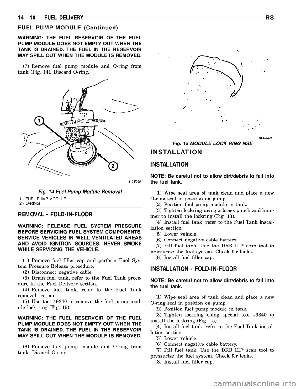
(7) Remove fuel pump module and O-ring from
tank (Fig. 14). Discard O-ring.
REMOVAL - FOLD-IN-FLOOR
WARNING: RELEASE FUEL SYSTEM PRESSURE
BEFORE SERVICING FUEL SYSTEM COMPONENTS.
SERVICE VEHICLES IN WELL VENTILATED AREAS
AND AVOID IGNITION SOURCES. NEVER SMOKE
WHILE SERVICING THE VEHICLE.
(1) Remove fuel filler cap and perform Fuel Sys-
tem Pressure Release procedure.
(2) Disconnect negative cable.
(3) Drain fuel tank, refer to the Fuel Tank proce-
dure in the Fuel Delivery section.
(4) Remove fuel tank, refer to the Fuel Tank
removal section.
(5) Use tool #9340 to remove the fuel pump mod-
ule lock ring (Fig. 15).
WARNING: THE FUEL RESERVOIR OF THE FUEL
PUMP MODULE DOES NOT EMPTY OUT WHEN THE
TANK IS DRAINED. THE FUEL IN THE RESERVOIR
MAY SPILL OUT WHEN THE MODULE IS REMOVED.
(6) Remove fuel pump module and O-ring from
tank. Discard O-ring.
INSTALLATION
INSTALLATION
NOTE: Be careful not to allow dirt/debris to fall into
the fuel tank.
(1) Wipe seal area of tank clean and place a new
O-ring seal in position on pump.
(2) Position fuel pump module in tank.
(3) Tighten lockring using a brass punch and ham-
mer to install the lockring (Fig. 13).
(4) Install fuel tank, refer to the Fuel Tank instal-
lation section.
(5) Lower vehicle.
(6) Connect negative cable battery.
(7) Fill fuel tank. Use the DRB IIItscan tool to
pressurize the fuel system. Check for leaks.
(8) Install fuel filler cap.
INSTALLATION - FOLD-IN-FLOOR
NOTE: Be careful not to allow dirt/debris to fall into
the fuel tank.
(1) Wipe seal area of tank clean and place a new
O-ring seal in position on pump.
(2) Position fuel pump module in tank.
(3) Tighten lockring using special tool #9340 to
install the lockring (Fig. 15).
(4) Install fuel tank, refer to the Fuel Tank instal-
lation section.
(5) Lower vehicle.
(6) Connect negative cable battery.
(7) Fill fuel tank. Use the DRB IIItscan tool to
pressurize the fuel system. Check for leaks.
(8) Install fuel filler cap.
Fig. 14 Fuel Pump Module Removal
1 - FUEL PUMP MODULE
2 - O-RING
Fig. 15 MODULE LOCK RING NSE
14 - 10 FUEL DELIVERYRS
FUEL PUMP MODULE (Continued)
Page 1377 of 2339
INSTALLATION - 3.3/3.8L
(1) Ensure injector holes are clean. Replace
O-rings if damaged.
(2) Lubricate injector O-rings with a drop of clean
engine oil to ease installation.
(3) Put the tip of each injector into their ports.
Push the assembly into place until the injectors are
seated in the ports.
(4) Install the fuel rail mounting bolts. Tighten
bolts to 22 N´m (200 in. lbs.) torque.
(5) Remove covering on lower intake manifold and
clean surface.
(6) Install the Upper Intake Manifold, refer to
Engine/Manifolds/Upper Intake for more information.
(7) Install fuel hose quick connector fitting to chas-
sis tubes.Refer to Fuel Hoses, Clamps and
Quick Connect Fittings in this Section.Push the
fitting onto the chassis tube until it clicks into place.
Pull on the fitting to ensure complete insertion.
(8) Connect negative cable to battery.
(9) Use the DRBIIItscan tool to pressurize the
fuel system. Check for leaks.
FUEL TANK
DESCRIPTION
The fuel tank is constructed of a plastic material.
Its main functions are for fuel storage and for place-
ment of the fuel pump module. The tank is made
from High density Polyethylene (HDPE) material.If
equipped with ORVR (Onboard Refueling Vapor
Recovery) it has been added to the fuel tank to con-
trol refueling vapor emissions.
OPERATION
All models pass a full 360 degree rollover test
without fuel leakage. To accomplish this, fuel and
vapor flow controls are required for all fuel tank con-
nections.
All models are equipped with either one or two
check valves mounted into the top of the fuel tank (or
pump module).
An evaporation control system is connected to the
check valve(s)/control valve(Refer to 25 - EMIS-
SIONS CONTROL/EVAPORATIVE EMISSIONS/
ORVR - OPERATION) to reduce emissions of fuel
vapors into the atmosphere, when the tank is vented
due to vapor expansion in the tank. When fuel evap-
orates from the fuel tank, vapors pass through vent
hoses or tubes to a charcoal canister where they are
temporarily held. When the engine is running, the
vapors are drawn into the intake manifold. In addi-
tion, fuel vapors produced during vehicle refueling
are allowed to pass through the vent hoses/tubes to
the charcoal canister(s) for temporary storage (priorto being drawn into the intake manifold). All models
are equipped with a self-diagnosing system using a
Leak Detection Pump (LDP) or Natural Vacuum
Leak Detection (NVLD). Refer to the Emission Con-
trol System for additional information.
INLET CHECK VALVE
All vehicles have an inlet check valve on the inside
of the fuel tank at the filler inlet
The valve prevents fuel from splashing back on
customer during vehicle refueling. The valve is a
non-serviceable item.
REMOVAL
REMOVAL
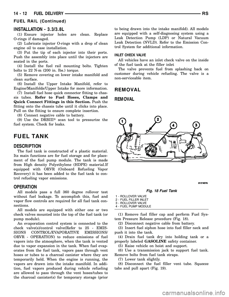
(1) Remove fuel filler cap and perform Fuel Sys-
tem Pressure Release procedure (Fig. 18).
(2) Disconnect negative cable from battery.
(3) Insert fuel siphon hose into fuel filler neck and
push it into the tank.
(4) Drain fuel tank dry into holding tank or a
properly labeledGASOLINEsafety container.
(5) Raise vehicle on hoist and support.
(6) Use a transmission jack to support fuel tank.
Remove bolts from fuel tank straps.
(7) Lower tank slightly.
(8) Disconnect the fuel filler vent tube. Squeeze
tabs and pull apart (Fig. 19).
Fig. 18 Fuel Tank
1 - ROLLOVER VALVE
2 - FUEL FILLER INLET
3 - ROLLOVER VALVE
4 - FUEL PUMP MODULE
14 - 12 FUEL DELIVERYRS
FUEL RAIL (Continued)
Page 1378 of 2339
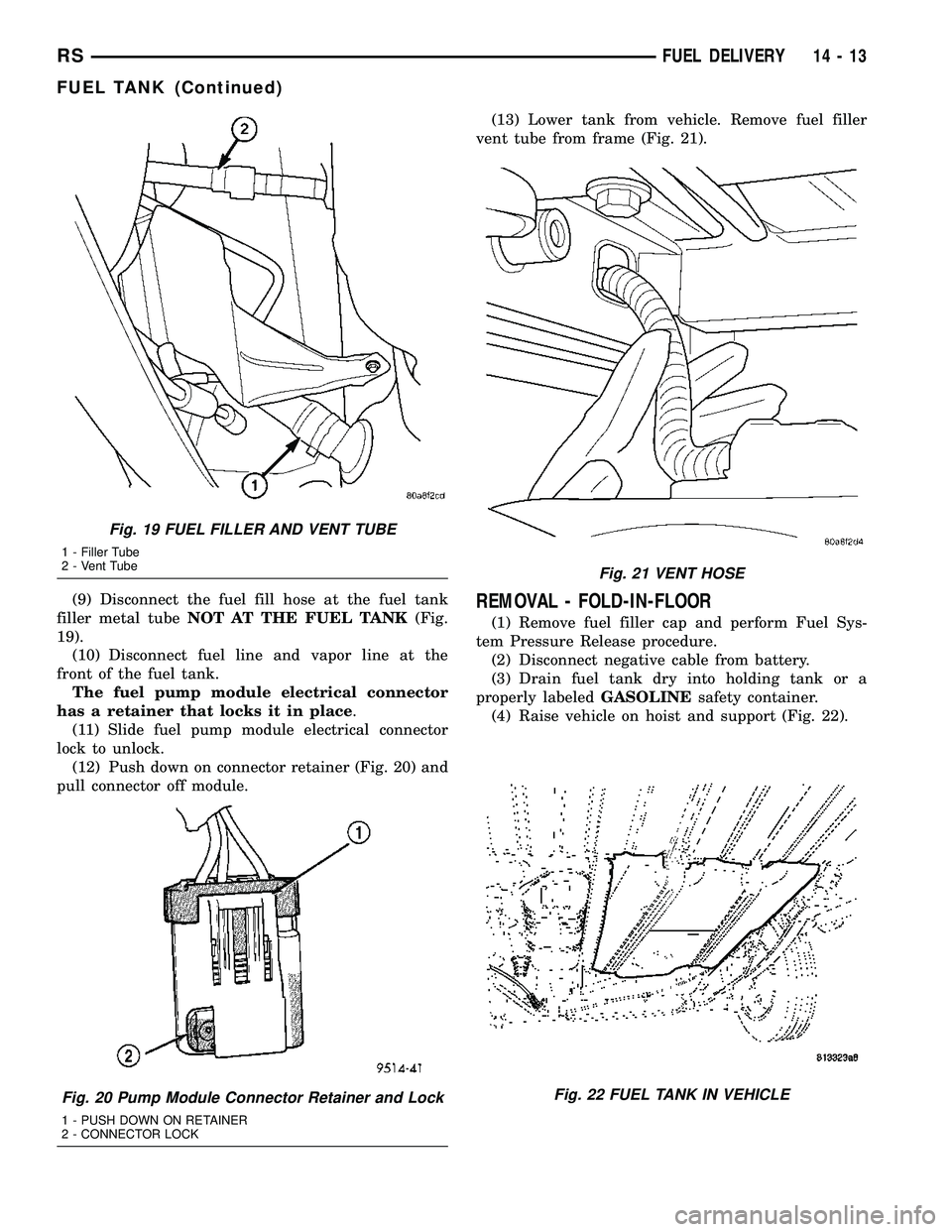
(9) Disconnect the fuel fill hose at the fuel tank
filler metal tubeNOT AT THE FUEL TANK(Fig.
19).
(10) Disconnect fuel line and vapor line at the
front of the fuel tank.
The fuel pump module electrical connector
has a retainer that locks it in place.
(11) Slide fuel pump module electrical connector
lock to unlock.
(12) Push down on connector retainer (Fig. 20) and
pull connector off module.(13) Lower tank from vehicle. Remove fuel filler
vent tube from frame (Fig. 21).REMOVAL - FOLD-IN-FLOOR
(1) Remove fuel filler cap and perform Fuel Sys-
tem Pressure Release procedure.
(2) Disconnect negative cable from battery.
(3) Drain fuel tank dry into holding tank or a
properly labeledGASOLINEsafety container.
(4) Raise vehicle on hoist and support (Fig. 22).
Fig. 19 FUEL FILLER AND VENT TUBE
1 - Filler Tube
2 - Vent Tube
Fig. 20 Pump Module Connector Retainer and Lock
1 - PUSH DOWN ON RETAINER
2 - CONNECTOR LOCK
Fig. 21 VENT HOSE
Fig. 22 FUEL TANK IN VEHICLE
RSFUEL DELIVERY14-13
FUEL TANK (Continued)
Page 1381 of 2339
INSTALLATION - FOLD-IN-FLOOR
(1) Use a transmission jack to support fuel tank.
(2) Raise tank and install fuel filler vent tube thru
frame (Fig. 29).
(3) Raise tank.
(4) Connect the fuel fill hose at the fuel tank filler
metal tube and tighten clamp.
CAUTION: Ensure straps are not twisted or bent
before or after tightening strap bolts.
(5) Install bolts for fuel tank straps (Fig. 23).
(6) Tighten strap bolts to 54 N´m (40 ft. lbs.)
torque. Remove transmission jack.
(7) Connect the fuel filler vent tube.
(8) Connect fuel line and vapor line at the front of
the fuel tank (Fig. 25), (Fig. 26).
(9) Connect the electrical connector.
(10) Slide fuel pump module electrical connector
lock to lock (Fig. 27), (Fig. 28).
(11) Lower vehicle.
(12) Fill fuel tank, replace cap, and connect bat-
tery negative cable.
(13) Use the DRBIIItscan tool to pressurize the
fuel system. Check for leaks.
FUEL TANK FILLER TUBE
REMOVAL
(1) Disconnect the negative battery cable.
(2) Remove the 3 screws at the filler door.
(3) Raise and support vehicle
(4) Remove the left rear tire.
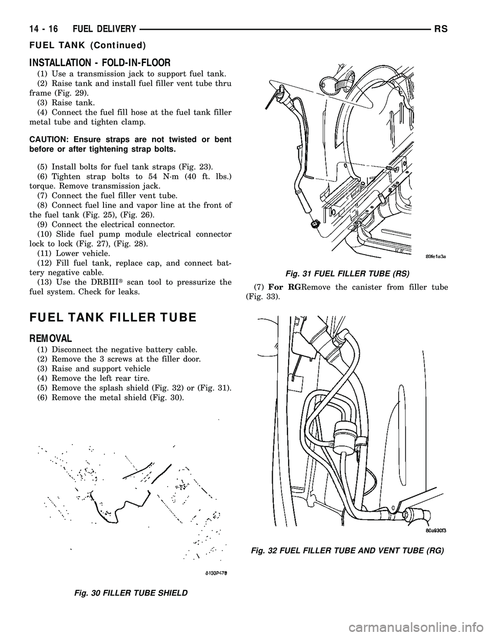
(5) Remove the splash shield (Fig. 32) or (Fig. 31).
(6) Remove the metal shield (Fig. 30).(7)For RGRemove the canister from filler tube
(Fig. 33).
Fig. 30 FILLER TUBE SHIELD
Fig. 31 FUEL FILLER TUBE (RS)
Fig. 32 FUEL FILLER TUBE AND VENT TUBE (RG)
14 - 16 FUEL DELIVERYRS
FUEL TANK (Continued)
Page 1382 of 2339
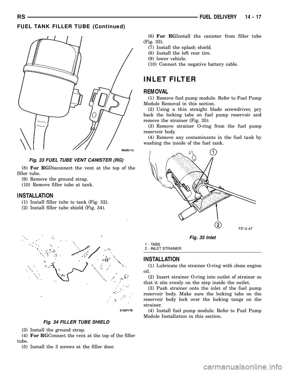
(8)For RGDisconnect the vent at the top of the
filler tube.
(9) Remove the ground strap.
(10) Remove filler tube at tank.
INSTALLATION
(1) Install filler tube to tank (Fig. 32).
(2) Install filler tube shield (Fig. 34).
(3) Install the ground strap.
(4)For RGConnect the vent at the top of the filler
tube.
(5) Install the 3 screws at the filler door.(6)For RGInstall the canister from filler tube
(Fig. 33).
(7) Install the splash shield.
(8) Install the left rear tire.
(9) lower vehicle.
(10) Connect the negative battery cable.
INLET FILTER
REMOVAL
(1) Remove fuel pump module. Refer to Fuel Pump
Module Removal in this section.
(2) Using a thin straight blade screwdriver, pry
back the locking tabs on fuel pump reservoir and
remove the strainer (Fig. 35).
(3) Remove strainer O-ring from the fuel pump
reservoir body.
(4) Remove any contaminants in the fuel tank by
washing the inside of the fuel tank.
INSTALLATION
(1) Lubricate the strainer O-ring with clean engine
oil.
(2) Insert strainer O-ring into outlet of strainer so
that it sits evenly on the step inside the outlet.
(3) Push strainer onto the inlet of the fuel pump
reservoir body. Make sure the locking tabs on the
reservoir body lock over the locking tangs on the
strainer.
(4) Install fuel pump module. Refer to Fuel Pump
Module Installation in this section.
Fig. 33 FUEL TUBE VENT CANISTER (RG)
Fig. 34 FILLER TUBE SHIELD
Fig. 35 Inlet
1 - TABS
2 - INLET STRAINER
RSFUEL DELIVERY14-17
FUEL TANK FILLER TUBE (Continued)
Page 1860 of 2339
CARPETS AND FLOOR MATS
REMOVAL
(1) Remove front seats. (Refer to 23 - BODY/
SEATS/SEAT - REMOVAL)
(2) Remove front center console.
(3) Remove heel blocker (plastic block below accel-
erator pedal).
(4) Remove the remaining seats. Refer to the Own-
er's Manual for the proper procedures.
(5) Remove front cowl panels and sill plates.
(6) Remove sliding door sill plates. (Refer to 23 -
BODY/INTERIOR/SLIDING DOOR SILL PLATE -
REMOVAL)
(7) Remove the cargo organizer, if equipped.
(8) Remove liftgate scuff plate. (Refer to 23 -
BODY/INTERIOR/LIFTGATE SCUFF PLATE -
REMOVAL)
(9) Remove lower B-pillar trim covers.
(10) Remove D-pillar trim covers.
(11) Remove Quarter trim panels.
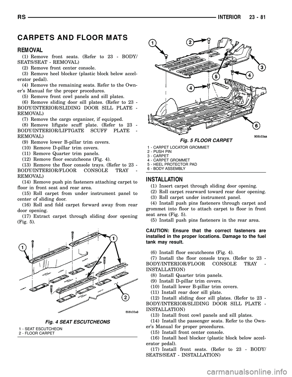
(12) Remove floor escutcheons (Fig. 4).
(13) Remove the floor console trays. (Refer to 23 -
BODY/INTERIOR/FLOOR CONSOLE TRAY -
REMOVAL)
(14) Remove push pin fasteners attaching carpet to
floor in front seat and rear area.
(15) Roll carpet from under instrument panel to
center of sliding door.
(16) Roll and fold carpet forward away from rear
door opening.
(17) Extract carpet through sliding door opening
(Fig. 5).
INSTALLATION
(1) Insert carpet through sliding door opening.
(2) Roll carpet rearward toward rear door opening.
(3) Roll carpet under instrument panel.
(4) Install push pins fasteners through carpet and
grommet into floor to attach carpet to floor in front
seat area (Fig. 5).
(5) Install push pins fasteners in the rear area.
CAUTION: Ensure that the correct fasteners are
installed in the proper locations. Damage to the fuel
tank may result.
(6) Install floor escutcheons (Fig. 4).
(7) Install the floor console trays. (Refer to 23 -
BODY/INTERIOR/FLOOR CONSOLE TRAY -
INSTALLATION)
(8) Install Quarter trim panels.
(9) Install D-pillar trim covers.
(10) Install lower B-pillar trim covers.
(11) Install rear door sill plate.
(12) Install sliding door sill plates. (Refer to 23 -
BODY/INTERIOR/SLIDING DOOR SILL PLATE -
INSTALLATION)
(13) Install front cowl panels and sill plates.
(14) Install the passenger seats. Refer to the Own-
er's Manual for proper procedures.
(15) Install front center console.
(16) Install heel blocker (plastic block below accel-
erator pedal).
(17) Install front seats. (Refer to 23 - BODY/
SEATS/SEAT - INSTALLATION)
Fig. 4 SEAT ESCUTCHEONS
1 - SEAT ESCUTCHEON
2 - FLOOR CARPET
Fig. 5 FLOOR CARPET
1 - CARPET LOCATOR GROMMET
2 - PUSH PIN
3 - CARPET
4 - CARPET GROMMET
5 - HEEL PROTECTOR PAD
6 - BODY ASSEMBLY
RSINTERIOR23-81
Page 2268 of 2339
FUEL DOSING PUMP
DESCRIPTION
The dosing pump is a combined delivery, dosing
and shut-off system for the fuel supply to the supple-
mental cabin heater from the vehicle fuel tank.
OPERATION
The dosing pump is an electrically operated pump
that receives its operation instructions from the sup-
plemental cabin heater control module. The pump
supplies diesel fuel from the vehicle fuel tank to the
cabin heater.
REMOVAL
NOTE: The dosing pump is serviceable without
removing the supplemental cabin heater from the
vehicle.
(1) Disconnect and isolate the negative battery
cable.
CAUTION: Make sure that the hoist is properly posi-
tioned under the vehicle to prevent damage to the
flexible section of the cabin heater exhaust tube.
(2) Raise and support the vehicle.
(3) Disconnect the wiring harness connector to the
dosing pump by depressing the integral spring and
pulling the connector away from the pump.
NOTE: Utilize an approved fuel storage container to
catch any residual fuel that may drain from the
heater fuel hose or the dosing pump.
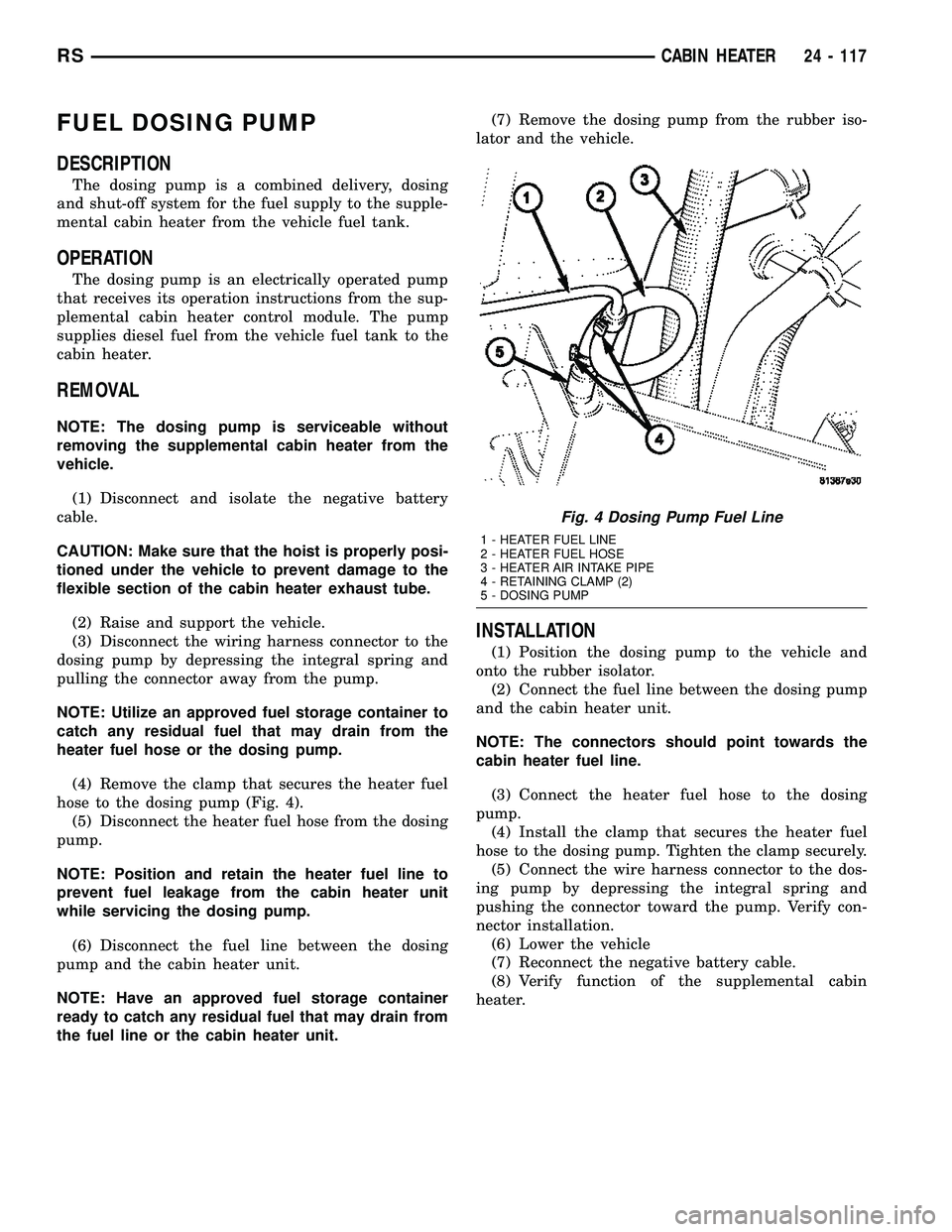
(4) Remove the clamp that secures the heater fuel
hose to the dosing pump (Fig. 4).
(5) Disconnect the heater fuel hose from the dosing
pump.
NOTE: Position and retain the heater fuel line to
prevent fuel leakage from the cabin heater unit
while servicing the dosing pump.
(6) Disconnect the fuel line between the dosing
pump and the cabin heater unit.
NOTE: Have an approved fuel storage container
ready to catch any residual fuel that may drain from
the fuel line or the cabin heater unit.(7) Remove the dosing pump from the rubber iso-
lator and the vehicle.
INSTALLATION
(1) Position the dosing pump to the vehicle and
onto the rubber isolator.
(2) Connect the fuel line between the dosing pump
and the cabin heater unit.
NOTE: The connectors should point towards the
cabin heater fuel line.
(3) Connect the heater fuel hose to the dosing
pump.
(4) Install the clamp that secures the heater fuel
hose to the dosing pump. Tighten the clamp securely.
(5) Connect the wire harness connector to the dos-
ing pump by depressing the integral spring and
pushing the connector toward the pump. Verify con-
nector installation.
(6) Lower the vehicle
(7) Reconnect the negative battery cable.
(8) Verify function of the supplemental cabin
heater.
Fig. 4 Dosing Pump Fuel Line
1 - HEATER FUEL LINE
2 - HEATER FUEL HOSE
3 - HEATER AIR INTAKE PIPE
4 - RETAINING CLAMP (2)
5 - DOSING PUMP
RSCABIN HEATER24 - 117
Page 2269 of 2339
FUEL LINE
STANDARD PROCEDURE
CLEANING
(1) Remove the cabin heater fuel line (Refer to 24 -
HEATING & AIR CONDITIONING/CABIN HEAT-
ER/FUEL LINE - REMOVAL).
(2) With the cabin heater fuel line removed from
the vehicle, place a shop cloth on the fuel tank end of
the fuel line to catch any residue, then apply a small
amount of air pressure to the other end of the fuel
line.
(3) Check to see if air pressure is coming from the
tank end of the line. If pressure is flowing unre-
stricted the line is clean.
(4) If the fuel line shows any signs of being
restricted after air pressure is applied, the fuel line
should be replaced.
(5) Install the cabin heater fuel line (Refer to 24 -
HEATING & AIR CONDITIONING/CABIN HEAT-
ER/FUEL LINE - INSTALLATION).
(6) Verify function of the cabin heater.
REMOVAL
CAUTION: Make sure that the hoist is properly posi-
tioned under the vehicle to prevent damage to the
flexible section of the cabin heater exhaust tube.
(1) Raise and support the vehicle.
NOTE: Utilize an approved fuel storage container to
catch any residual fuel that may drain from the
heater fuel hose or the dosing pump.
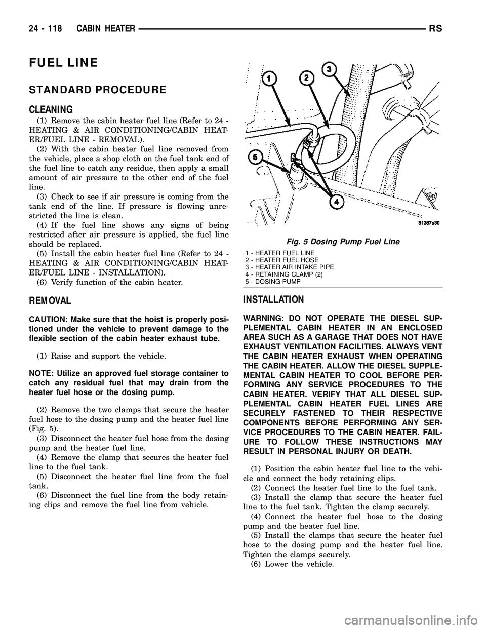
(2) Remove the two clamps that secure the heater
fuel hose to the dosing pump and the heater fuel line
(Fig. 5).
(3) Disconnect the heater fuel hose from the dosing
pump and the heater fuel line.
(4) Remove the clamp that secures the heater fuel
line to the fuel tank.
(5) Disconnect the heater fuel line from the fuel
tank.
(6) Disconnect the fuel line from the body retain-
ing clips and remove the fuel line from vehicle.
INSTALLATION
WARNING: DO NOT OPERATE THE DIESEL SUP-
PLEMENTAL CABIN HEATER IN AN ENCLOSED
AREA SUCH AS A GARAGE THAT DOES NOT HAVE
EXHAUST VENTILATION FACILITIES. ALWAYS VENT
THE CABIN HEATER EXHAUST WHEN OPERATING
THE CABIN HEATER. ALLOW THE DIESEL SUPPLE-
MENTAL CABIN HEATER TO COOL BEFORE PER-
FORMING ANY SERVICE PROCEDURES TO THE
CABIN HEATER. VERIFY THAT ALL DIESEL SUP-
PLEMENTAL CABIN HEATER FUEL LINES ARE
SECURELY FASTENED TO THEIR RESPECTIVE
COMPONENTS BEFORE PERFORMING ANY SER-
VICE PROCEDURES TO THE CABIN HEATER. FAIL-
URE TO FOLLOW THESE INSTRUCTIONS MAY
RESULT IN PERSONAL INJURY OR DEATH.
(1) Position the cabin heater fuel line to the vehi-
cle and connect the body retaining clips.
(2) Connect the heater fuel line to the fuel tank.
(3) Install the clamp that secure the heater fuel
line to the fuel tank. Tighten the clamp securely.
(4) Connect the heater fuel hose to the dosing
pump and the heater fuel line.
(5) Install the clamps that secure the heater fuel
hose to the dosing pump and the heater fuel line.
Tighten the clamps securely.
(6) Lower the vehicle.
Fig. 5 Dosing Pump Fuel Line
1 - HEATER FUEL LINE
2 - HEATER FUEL HOSE
3 - HEATER AIR INTAKE PIPE
4 - RETAINING CLAMP (2)
5 - DOSING PUMP
24 - 118 CABIN HEATERRS