2005 CHRYSLER CARAVAN wiring
[x] Cancel search: wiringPage 1127 of 2339
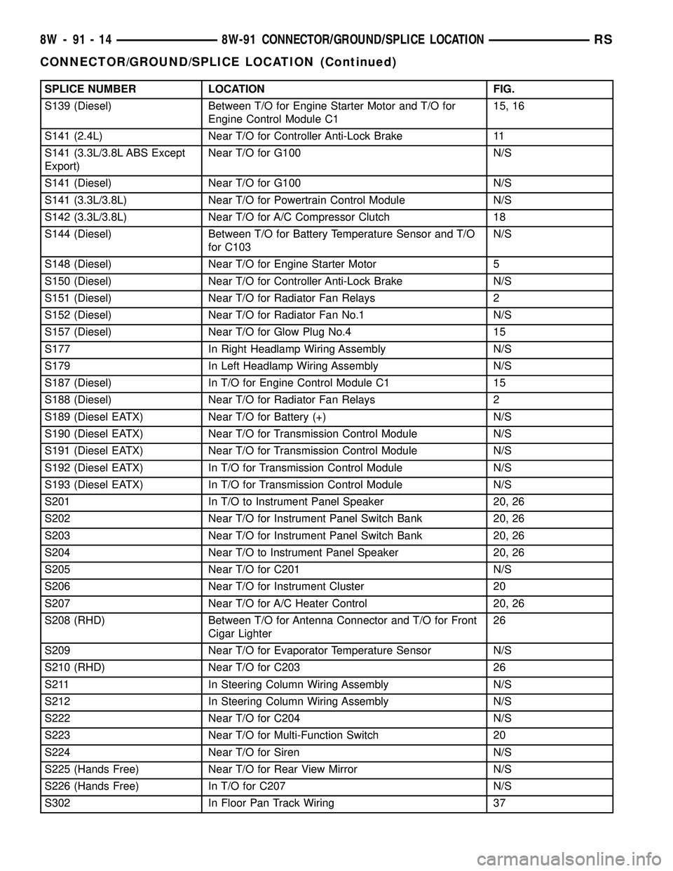
SPLICE NUMBER LOCATION FIG.
S139 (Diesel) Between T/O for Engine Starter Motor and T/O for
Engine Control Module C115, 16
S141 (2.4L) Near T/O for Controller Anti-Lock Brake 11
S141 (3.3L/3.8L ABS Except
Export)Near T/O for G100 N/S
S141 (Diesel) Near T/O for G100 N/S
S141 (3.3L/3.8L) Near T/O for Powertrain Control Module N/S
S142 (3.3L/3.8L) Near T/O for A/C Compressor Clutch 18
S144 (Diesel) Between T/O for Battery Temperature Sensor and T/O
for C103N/S
S148 (Diesel) Near T/O for Engine Starter Motor 5
S150 (Diesel) Near T/O for Controller Anti-Lock Brake N/S
S151 (Diesel) Near T/O for Radiator Fan Relays 2
S152 (Diesel) Near T/O for Radiator Fan No.1 N/S
S157 (Diesel) Near T/O for Glow Plug No.4 15
S177 In Right Headlamp Wiring Assembly N/S
S179 In Left Headlamp Wiring Assembly N/S
S187 (Diesel) In T/O for Engine Control Module C1 15
S188 (Diesel) Near T/O for Radiator Fan Relays 2
S189 (Diesel EATX) Near T/O for Battery (+) N/S
S190 (Diesel EATX) Near T/O for Transmission Control Module N/S
S191 (Diesel EATX) Near T/O for Transmission Control Module N/S
S192 (Diesel EATX) In T/O for Transmission Control Module N/S
S193 (Diesel EATX) In T/O for Transmission Control Module N/S
S201 In T/O to Instrument Panel Speaker 20, 26
S202 Near T/O for Instrument Panel Switch Bank 20, 26
S203 Near T/O for Instrument Panel Switch Bank 20, 26
S204 Near T/O to Instrument Panel Speaker 20, 26
S205 Near T/O for C201 N/S
S206 Near T/O for Instrument Cluster 20
S207 Near T/O for A/C Heater Control 20, 26
S208 (RHD) Between T/O for Antenna Connector and T/O for Front
Cigar Lighter26
S209 Near T/O for Evaporator Temperature Sensor N/S
S210 (RHD) Near T/O for C203 26
S211 In Steering Column Wiring Assembly N/S
S212 In Steering Column Wiring Assembly N/S
S222 Near T/O for C204 N/S
S223 Near T/O for Multi-Function Switch 20
S224 Near T/O for Siren N/S
S225 (Hands Free) Near T/O for Rear View Mirror N/S
S226 (Hands Free) In T/O for C207 N/S
S302 In Floor Pan Track Wiring 37
8W - 91 - 14 8W-91 CONNECTOR/GROUND/SPLICE LOCATIONRS
CONNECTOR/GROUND/SPLICE LOCATION (Continued)
Page 1128 of 2339
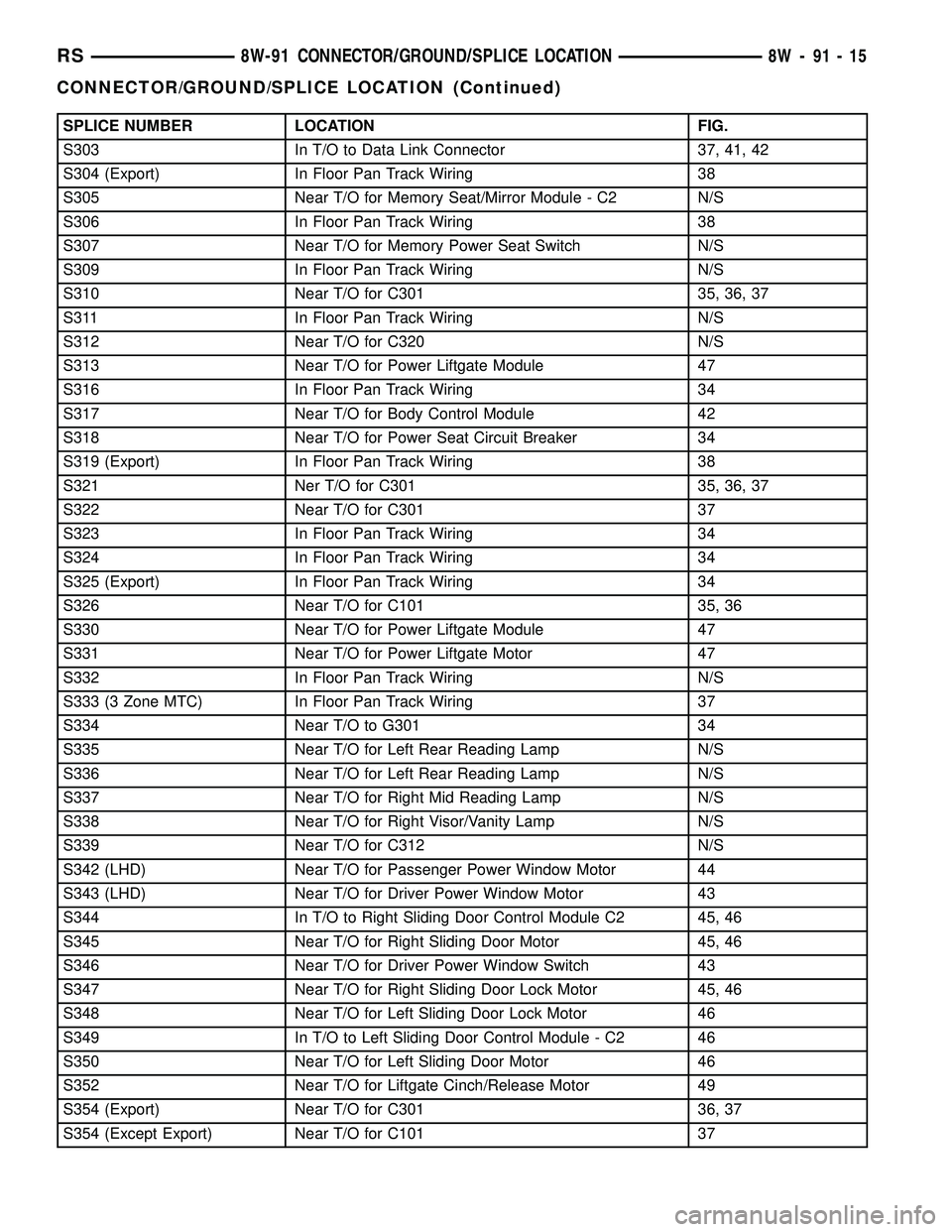
SPLICE NUMBER LOCATION FIG.
S303 In T/O to Data Link Connector 37, 41, 42
S304 (Export) In Floor Pan Track Wiring 38
S305 Near T/O for Memory Seat/Mirror Module - C2 N/S
S306 In Floor Pan Track Wiring 38
S307 Near T/O for Memory Power Seat Switch N/S
S309 In Floor Pan Track Wiring N/S
S310 Near T/O for C301 35, 36, 37
S311 In Floor Pan Track Wiring N/S
S312 Near T/O for C320 N/S
S313 Near T/O for Power Liftgate Module 47
S316 In Floor Pan Track Wiring 34
S317 Near T/O for Body Control Module 42
S318 Near T/O for Power Seat Circuit Breaker 34
S319 (Export) In Floor Pan Track Wiring 38
S321 Ner T/O for C301 35, 36, 37
S322 Near T/O for C301 37
S323 In Floor Pan Track Wiring 34
S324 In Floor Pan Track Wiring 34
S325 (Export) In Floor Pan Track Wiring 34
S326 Near T/O for C101 35, 36
S330 Near T/O for Power Liftgate Module 47
S331 Near T/O for Power Liftgate Motor 47
S332 In Floor Pan Track Wiring N/S
S333 (3 Zone MTC) In Floor Pan Track Wiring 37
S334 Near T/O to G301 34
S335 Near T/O for Left Rear Reading Lamp N/S
S336 Near T/O for Left Rear Reading Lamp N/S
S337 Near T/O for Right Mid Reading Lamp N/S
S338 Near T/O for Right Visor/Vanity Lamp N/S
S339 Near T/O for C312 N/S
S342 (LHD) Near T/O for Passenger Power Window Motor 44
S343 (LHD) Near T/O for Driver Power Window Motor 43
S344 In T/O to Right Sliding Door Control Module C2 45, 46
S345 Near T/O for Right Sliding Door Motor 45, 46
S346 Near T/O for Driver Power Window Switch 43
S347 Near T/O for Right Sliding Door Lock Motor 45, 46
S348 Near T/O for Left Sliding Door Lock Motor 46
S349 In T/O to Left Sliding Door Control Module - C2 46
S350 Near T/O for Left Sliding Door Motor 46
S352 Near T/O for Liftgate Cinch/Release Motor 49
S354 (Export) Near T/O for C301 36, 37
S354 (Except Export) Near T/O for C101 37
RS8W-91 CONNECTOR/GROUND/SPLICE LOCATION8W-91-15
CONNECTOR/GROUND/SPLICE LOCATION (Continued)
Page 1129 of 2339
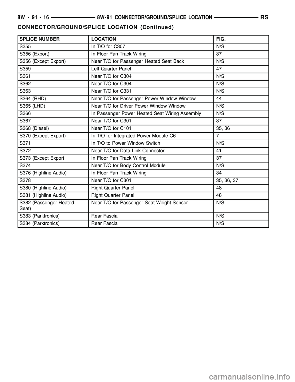
SPLICE NUMBER LOCATION FIG.
S355 In T/O for C307 N/S
S356 (Export) In Floor Pan Track Wiring 37
S356 (Except Export) Near T/O for Passenger Heated Seat Back N/S
S359 Left Quarter Panel 47
S361 Near T/O for C304 N/S
S362 Near T/O for C304 N/S
S363 Near T/O for C331 N/S
S364 (RHD) Near T/O for Passenger Power Window Window 44
S365 (LHD) Near T/O for Driver Power Window Window N/S
S366 In Passenger Power Heated Seat Wiring Assembly N/S
S367 Near T/O for C301 37
S368 (Diesel) Near T/O for C101 35, 36
S370 (Except Export) In T/O for Integrated Power Module C6 7
S371 In T/O to Power Window Switch N/S
S372 Near T/O for Data Link Connector 41
S373 (Except Export In Floor Pan Track Wiring 37
S374 Near T/O for Body Control Module N/S
S376 (Highline Audio) In Floor Pan Track Wiring 34
S378 Near T/O for C301 35, 36, 37
S380 (Highline Audio) Right Quarter Panel 48
S381 (Highline Audio) Right Quarter Panel 48
S382 (Passenger Heated
Seat)Near T/O for Passenger Seat Weight Sensor N/S
S383 (Parktronics) Rear Fascia N/S
S384 (Parktronics) Rear Fascia N/S
8W - 91 - 16 8W-91 CONNECTOR/GROUND/SPLICE LOCATIONRS
CONNECTOR/GROUND/SPLICE LOCATION (Continued)
Page 1174 of 2339
8W-97 POWER DISTRIBUTION SYSTEM
TABLE OF CONTENTS
page page
POWER DISTRIBUTION SYSTEM
DESCRIPTION..........................1
OPERATION............................1
SPECIAL TOOLS
POWER DISTRIBUTION SYSTEMS.........1
INTEGRATED POWER MODULE
DESCRIPTION..........................1
OPERATION............................2
REMOVAL.............................2
INSTALLATION..........................2IOD FUSE
DESCRIPTION..........................3
OPERATION............................3
POWER OUTLET
DESCRIPTION..........................3
OPERATION............................3
DIAGNOSIS AND TESTING
DIAGNOSIS & TESTING - POWER OUTLET . . 3
REMOVAL.............................4
INSTALLATION..........................4
POWER DISTRIBUTION
SYSTEM
DESCRIPTION
The power distribution system for this vehicle con-
sists of the following components:
²Integrated Power Module (IPM)
²Front Control Module (FCM)
²Power Outlets
Refer to Wiring Diagrams for complete circuit sche-
matics.
The power distribution system also incorporates
various types of circuit control and protection fea-
tures, including:
²Automatic resetting circuit breakers
²Blade-type fuses
²Bus bars
²Cartridge fuses
²Circuit splice blocks
²Flashers
²Fusible links
²Relays
OPERATION
The power distribution system for this vehicle is
designed to provide safe, reliable, and centralized dis-
tribution points for the electrical current required to
operate all of the many standard and optional facto-
ry-installed electrical and electronic powertrain,
chassis, safety, security, comfort and convenience sys-
tems. At the same time, the power distribution sys-
tem was designed to provide ready access to these
electrical distribution points for the vehicle techni-
cian to use when conducting diagnosis and repair of
faulty circuits. The power distribution system can
also prove useful for the sourcing of additional elec-
trical circuits that may be required to provide theelectrical current needed to operate many accessories
that the vehicle owner may choose to have installed.
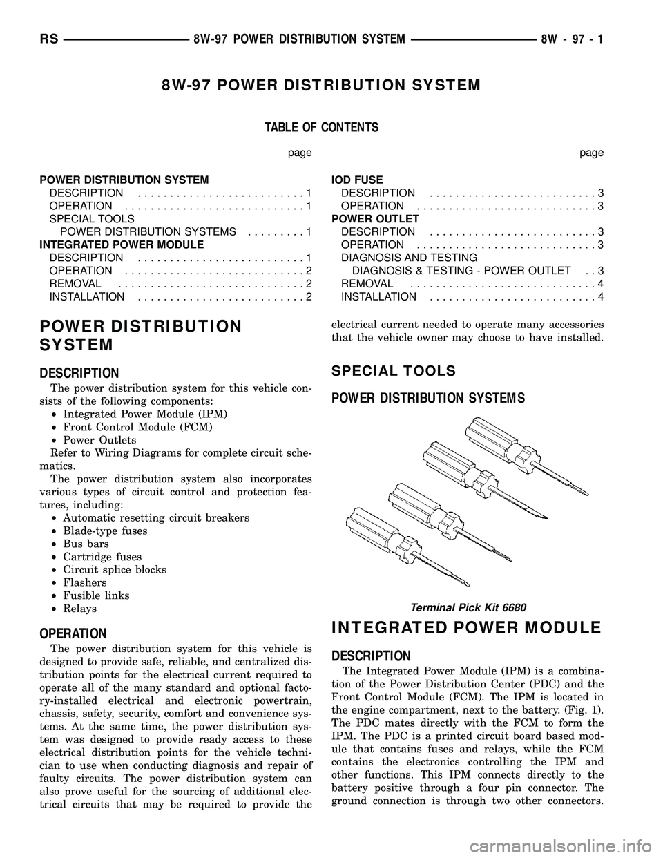
SPECIAL TOOLS
POWER DISTRIBUTION SYSTEMS
INTEGRATED POWER MODULE
DESCRIPTION
The Integrated Power Module (IPM) is a combina-
tion of the Power Distribution Center (PDC) and the
Front Control Module (FCM). The IPM is located in
the engine compartment, next to the battery. (Fig. 1).
The PDC mates directly with the FCM to form the
IPM. The PDC is a printed circuit board based mod-
ule that contains fuses and relays, while the FCM
contains the electronics controlling the IPM and
other functions. This IPM connects directly to the
battery positive through a four pin connector. The
ground connection is through two other connectors.
Terminal Pick Kit 6680
RS8W-97 POWER DISTRIBUTION SYSTEM8W-97-1
Page 1190 of 2339
(9) Using a blade or suitable hose cutter, cut trans-
axle oil cooler lines off flush with fittings. Plug cooler
lines and fittings to prevent debris from entering
transaxle or cooler circuit. A service splice kit will be
installed upon reassembly.
(10) Disconnect transmission shift linkage and
electrical connectors.
(11) Disconnect throttle body linkage.
(12) Disconnect engine wiring harness.
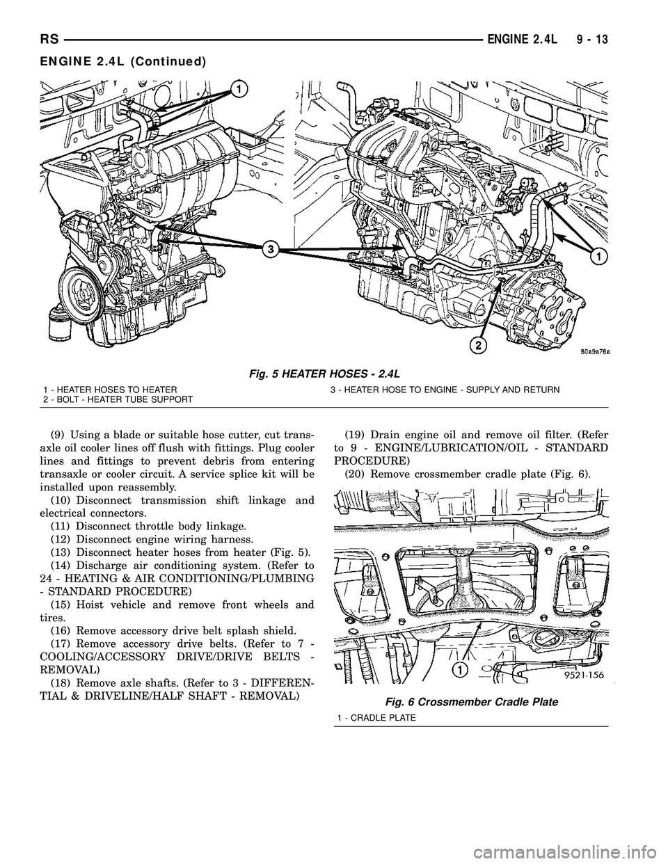
(13) Disconnect heater hoses from heater (Fig. 5).
(14) Discharge air conditioning system. (Refer to
24 - HEATING & AIR CONDITIONING/PLUMBING
- STANDARD PROCEDURE)
(15) Hoist vehicle and remove front wheels and
tires.
(16) Remove accessory drive belt splash shield.
(17) Remove accessory drive belts. (Refer to 7 -
COOLING/ACCESSORY DRIVE/DRIVE BELTS -
REMOVAL)
(18) Remove axle shafts. (Refer to 3 - DIFFEREN-
TIAL & DRIVELINE/HALF SHAFT - REMOVAL)(19) Drain engine oil and remove oil filter. (Refer
to 9 - ENGINE/LUBRICATION/OIL - STANDARD
PROCEDURE)
(20) Remove crossmember cradle plate (Fig. 6).
Fig. 5 HEATER HOSES - 2.4L
1 - HEATER HOSES TO HEATER 3 - HEATER HOSE TO ENGINE - SUPPLY AND RETURN
2 - BOLT - HEATER TUBE SUPPORT
Fig. 6 Crossmember Cradle Plate
1 - CRADLE PLATE
RSENGINE 2.4L9-13
ENGINE 2.4L (Continued)
Page 1205 of 2339
(5) Install rocker arms. (Refer to 9 - ENGINE/
CYLINDER HEAD/ROCKER ARMS - INSTALLA-
TION)
(6) Install camshafts. (Refer to 9 - ENGINE/CYL-
INDER HEAD/CAMSHAFT(S) - INSTALLATION).
(7) Install cylinder head cover. (Refer to 9 -
ENGINE/CYLINDER HEAD/CYLINDER HEAD
COVER(S) - INSTALLATION)
(8) Install timing belt rear cover and timing belt
idler pulley. (Refer to 9 - ENGINE/VALVE TIMING/
TIMING BELT / CHAIN COVER(S) - INSTALLA-
TION)
(9) Install timing belt and camshaft sprockets.
(Refer to 9 - ENGINE/VALVE TIMING/TIMING
BELT/CHAIN AND SPROCKETS - INSTALLATION)
(10) Connect cam sensor and fuel injectors wiring
connectors.
(11) Install ignition coil and wires. Connect igni-
tion coil wiring connector.
(12) Install power steering pump reservoir and
line support bracket to cylinder head.
(13) Raise vehicle and install the exhaust pipe to
the manifold.(14) Install accessory drive belts. (Refer to 7 -
COOLING/ACCESSORY DRIVE/DRIVE BELTS -
INSTALLATION)
(15) Install heater tube support bracket to cylinder
head.
(16) Connect radiator upper and heater hoses to
intake manifold water outlet connections.
(17) Install upper intake manifold. (Refer to 9 -
ENGINE/MANIFOLDS/INTAKE MANIFOLD -
INSTALLATION)
(18) Using new gaskets, install EGR tube and
tighten fasteners to 11 N´m (95 in. lbs.).
(19) Install air inlet tube and housing.
(20) Connect all vacuum lines, electrical wiring,
ground straps and fuel line.
(21) Fill cooling system. (Refer to 7 - COOLING -
STANDARD PROCEDURE)
(22) Connect battery negative cable.
CAMSHAFT OIL SEAL(S)
REMOVAL
(1) Remove timing belt (Refer to 9 - ENGINE/
VALVE TIMING/TIMING BELT AND SPROCKETS -
REMOVAL).
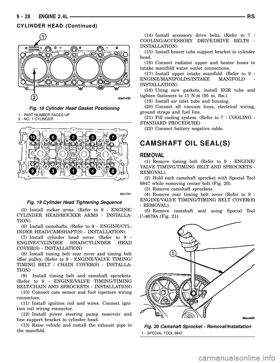
(2) Hold each camshaft sprocket with Special Tool
6847 while removing center bolt (Fig. 20).
(3) Remove camshaft sprockets.
(4) Remove rear timing belt cover (Refer to 9 -
ENGINE/VALVE TIMING/TIMING BELT COVER(S)
- REMOVAL).
(5) Remove camshaft seal using Special Tool
C-4679A (Fig. 21).
Fig. 18 Cylinder Head Gasket Positioning
1 - PART NUMBER FACES UP
2 - NO. 1 CYLINDER
Fig. 19 Cylinder Head Tightening Sequence
Fig. 20 Camshaft Sprocket - Removal/Installation
1 - SPECIAL TOOL 6847
9 - 28 ENGINE 2.4LRS
CYLINDER HEAD (Continued)
Page 1239 of 2339
INTAKE MANIFOLD - LOWER
REMOVAL
(1) Perform fuel system pressure release proce-
durebefore attempting any repairs.(Refer to 14 -
FUEL SYSTEM/FUEL DELIVERY - STANDARD
PROCEDURE)
(2) Remove upper intake manifold. (Refer to 9 -
ENGINE/MANIFOLDS/INTAKE MANIFOLD -
REMOVAL)
CAUTION: Cover intake manifold openings to pre-
vent foreign material from entering engine.
(3) Disconnect fuel line. (Refer to 14 - FUEL SYS-
TEM/FUEL DELIVERY/QUICK CONNECT FIT-
TING - STANDARD PROCEDURE)
(4) Drain the cooling system. (Refer to 7 - COOL-
ING - STANDARD PROCEDURE)
(5) Remove heater supply and radiator upper
hoses at intake manifold.
(6) Disconnect coolant temperature sensor/fuel
injector wire harness connector.
(7) Remove lower intake manifold support bracket
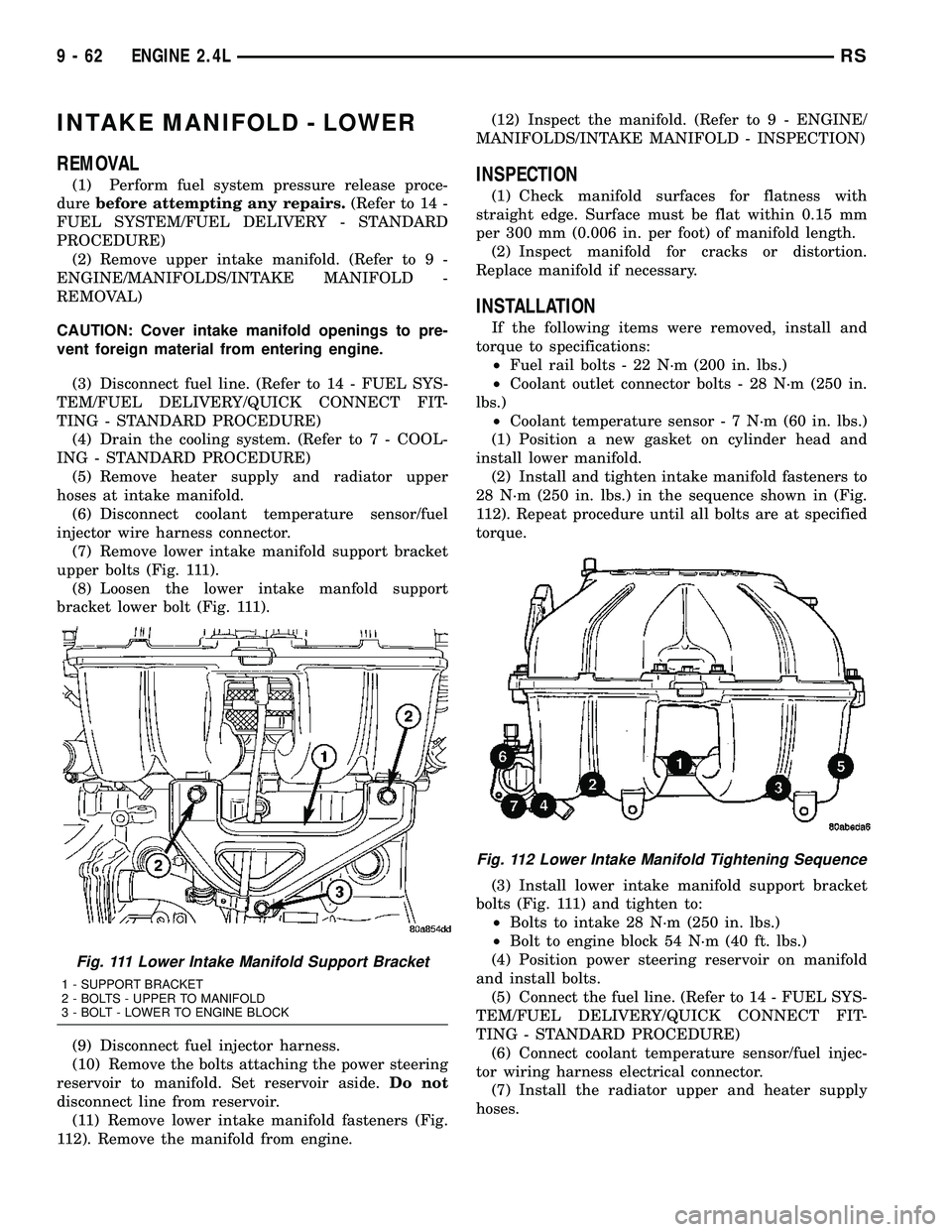
upper bolts (Fig. 111).
(8) Loosen the lower intake manfold support
bracket lower bolt (Fig. 111).
(9) Disconnect fuel injector harness.
(10) Remove the bolts attaching the power steering
reservoir to manifold. Set reservoir aside.Do not
disconnect line from reservoir.
(11) Remove lower intake manifold fasteners (Fig.
112). Remove the manifold from engine.(12) Inspect the manifold. (Refer to 9 - ENGINE/
MANIFOLDS/INTAKE MANIFOLD - INSPECTION)INSPECTION
(1) Check manifold surfaces for flatness with
straight edge. Surface must be flat within 0.15 mm
per 300 mm (0.006 in. per foot) of manifold length.
(2) Inspect manifold for cracks or distortion.
Replace manifold if necessary.
INSTALLATION
If the following items were removed, install and
torque to specifications:
²Fuel rail bolts - 22 N´m (200 in. lbs.)
²Coolant outlet connector bolts - 28 N´m (250 in.
lbs.)
²Coolant temperature sensor - 7 N´m (60 in. lbs.)
(1) Position a new gasket on cylinder head and
install lower manifold.
(2) Install and tighten intake manifold fasteners to
28 N´m (250 in. lbs.) in the sequence shown in (Fig.
112). Repeat procedure until all bolts are at specified
torque.
(3) Install lower intake manifold support bracket
bolts (Fig. 111) and tighten to:
²Bolts to intake 28 N´m (250 in. lbs.)
²Bolt to engine block 54 N´m (40 ft. lbs.)
(4) Position power steering reservoir on manifold
and install bolts.
(5) Connect the fuel line. (Refer to 14 - FUEL SYS-
TEM/FUEL DELIVERY/QUICK CONNECT FIT-
TING - STANDARD PROCEDURE)
(6) Connect coolant temperature sensor/fuel injec-
tor wiring harness electrical connector.
(7) Install the radiator upper and heater supply
hoses.
Fig. 111 Lower Intake Manifold Support Bracket
1 - SUPPORT BRACKET
2 - BOLTS - UPPER TO MANIFOLD
3 - BOLT - LOWER TO ENGINE BLOCK
Fig. 112 Lower Intake Manifold Tightening Sequence
9 - 62 ENGINE 2.4LRS
Page 1267 of 2339
(41) Disconnect the knock sensor electrical connec-
tor (3.8L only).
(42) Disconnect the engine block heater electrical
connector (if equipped).
(43) Remove the accessory belt splash shield.
(44) Remove accessory drive belt (Refer to 7 -
COOLING/ACCESSORY DRIVE/DRIVE BELTS -
REMOVAL).
(45) Disconnect the radiator lower hose.
(46) Remove air conditioning compressor from
engine.
(47) Remove the generator (Refer to 8 - ELECTRI-
CAL/CHARGING/GENERATOR - REMOVAL).
(48) Remove the water pump pulley attaching
bolts and position pulley between pump hub and
housing.
(49) Disconnect the oil pressure switch electrical
connector.
(50) Disconnect wiring harness support clip from
engine oil dipstick tube.
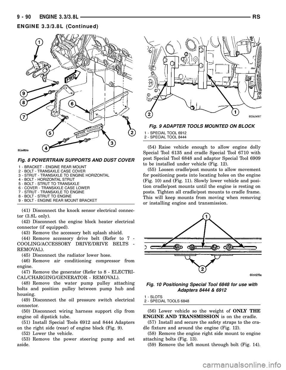
(51) Install Special Tools 6912 and 8444 Adapters
on the right side (rear) of engine block (Fig. 9).
(52) Lower the vehicle.
(53) Remove the power steering pump and set
aside.(54) Raise vehicle enough to allow engine dolly
Special Tool 6135 and cradle Special Tool 6710 with
post Special Tool 6848 and adaptor Special Tool 6909
to be installed under vehicle (Fig. 12).
(55) Loosen cradle/post mounts to allow movement
for positioning posts into locating holes on the engine
(Fig. 10) and (Fig. 11). Slowly lower vehicle and posi-
tion cradle/post mounts until the engine is resting on
posts. Tighten all cradle/post mounts to cradle frame.
This will keep mounts from moving when removing
or installing engine and transmission.
(56) Lower vehicle so the weight ofONLY THE
ENGINE AND TRANSMISSIONis on the cradle.
(57) Install and secure the safety straps to the cra-
dle fixture and around the engine (Fig. 12).
(58) Remove the engine right side mount to engine
attaching bolts (Fig. 13).
(59) Remove the left mount through bolt (Fig. 14).
Fig. 8 POWERTRAIN SUPPORTS AND DUST COVER
1 - BRACKET - ENGINE REAR MOUNT
2 - BOLT - TRANSAXLE CASE COVER
3 - STRUT - TRANSAXLE TO ENGINE HORIZONTAL
4 - BOLT - HORIZONTAL STRUT
5 - BOLT - STRUT TO TRANSAXLE
6 - COVER - TRANSAXLE CASE LOWER
7 - STRUT - TRANSAXLE TO ENGINE
8 - BOLT - STRUT TO ENGINE
9 - BOLT - ENGINE REAR MOUNT BRACKET
Fig. 9 ADAPTER TOOLS MOUNTED ON BLOCK
1 - SPECIAL TOOL 6912
2 - SPECIAL TOOL 8444
Fig. 10 Positioning Special Tool 6848 for use with
Adapters 8444 & 6912
1 - SLOTS
2 - SPECIAL TOOLS 6848
9 - 90 ENGINE 3.3/3.8LRS
ENGINE 3.3/3.8L (Continued)