2005 CHRYSLER CARAVAN tow
[x] Cancel search: towPage 1930 of 2339
SEAT RISER LATCH LOCKING
LINK
REMOVAL
(1) Remove seat as necessary to access latch lock-
ing link.
NOTE: If the seat is locked in the seated position
and cannot be tilted forward, it can be released by
reaching into the escutcheons with a hook tool or a
finger from the rear. Pulling the latch toward the
rear of the vehicle will unlock the seat latch allow-
ing the seat to tilt forward.
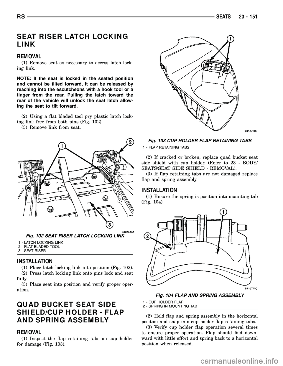
(2) Using a flat bladed tool pry plastic latch lock-
ing link free from both pins (Fig. 102).
(3) Remove link from seat.
INSTALLATION
(1) Place latch locking link into position (Fig. 102).
(2) Press latch locking link onto pins lock and seat
fully.
(3) Place seat into position and verify proper oper-
ation.
QUAD BUCKET SEAT SIDE
SHIELD/CUP HOLDER - FLAP
AND SPRING ASSEMBLY
REMOVAL
(1) Inspect the flap retaining tabs on cup holder
for damage (Fig. 103).(2) If cracked or broken, replace quad bucket seat
side shield with cup holder. (Refer to 23 - BODY/
SEATS/SEAT SIDE SHIELD - REMOVAL).
(3) If flap retaining tabs are not damaged replace
flap and spring assembly.
INSTALLATION
(1) Ensure the spring is position into mounting tab
(Fig. 104).
(2)
Hold flap and spring assembly in the horizontal
position and snap into cup holder flap retaining tabs.
(3) Verify cup holder flap operation several times
to ensure proper operation. Flap should fold down-
ward with little effort and spring back to a horizontal
position when released.
Fig. 102 SEAT RISER LATCH LOCKING LINK
1 - LATCH LOCKING LINK
2 - FLAT BLADED TOOL
3 - SEAT RISER
Fig. 103 CUP HOLDER FLAP RETAINING TABS
1 - FLAP RETAINING TABS
Fig. 104 FLAP AND SPRING ASSEMBLY
1 - CUP HOLDER FLAP
2 - SPRING IN MOUNTING TAB
RSSEATS23 - 151
Page 1937 of 2339
(4) Install seat cushion cover and foam. (Refer to
23 - BODY/SEATS/SEAT CUSHION COVER/FOAM -
INSTALLATION).
(5) Install handle to cushion.
(6) Install seat cushion pan bottom side panel (Fig.
126).
(7) Fold the third row seat into floor well.
(8) Place seat cushion pan carpet to floor panel
into position and push on panel to seat push pin fas-
teners (Fig. 125).
(9) Third row seat in the upright position.
(10) Install the third row cushion back cover (Fig.
124).
SEAT BACK PANEL - THIRD
ROW -FOLD-IN-FLOOR
REMOVAL
(1) Third row seat in the upright position.
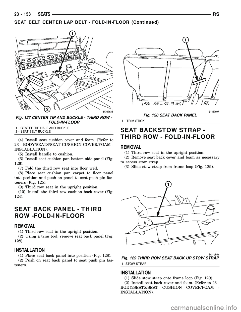
(2) Using a trim tool, remove seat back panel (Fig.
128).
INSTALLATION
(1) Place seat back panel into position (Fig. 128).
(2) Push on seat back panel to seat push pin fas-
teners.
SEAT BACKSTOW STRAP -
THIRD ROW - FOLD-IN-FLOOR
REMOVAL
(1) Third row seat in the upright position.
(2) Remove seat back cover and foam as necessary
to access stow strap
(3) Slide stow strap from frame loop (Fig. 129).
INSTALLATION
(1) Slide stow strap onto frame loop (Fig. 129).
(2) Install seat back cover and foam. (Refer to 23 -
BODY/SEATS/SEAT CUSHION COVER/FOAM -
INSTALLATION).
Fig. 127 CENTER TIP AND BUCKLE - THIRD ROW -
FOLD-IN-FLOOR
1 - CENTER TIP HALF AND BUCKLE
2 - SEAT BELT BUCKLE
Fig. 128 SEAT BACK PANEL
1 - TRIM STICK
Fig. 129 THIRD ROW SEAT BACK UP STOW STRAP
1- STOW STRAP
23 - 158 SEATSRS
SEAT BELT CENTER LAP BELT - FOLD-IN-FLOOR (Continued)
Page 1952 of 2339
(5) Verify sunroof operation and alignment.
REAR HOUSING HOSE
(1) Connect the new drain hose to the sunroof
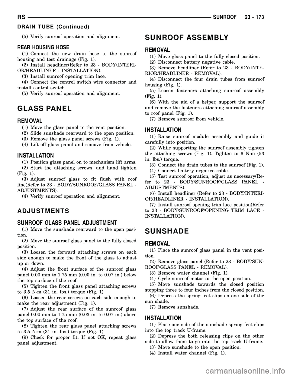
housing and test drainage (Fig. 1).
(2) Install headliner(Refer to 23 - BODY/INTERI-
OR/HEADLINER - INSTALLATION).
(3) Install sunroof opening trim lace.
(4) Connect the control switch wire connector and
install control switch.
(5) Verify sunroof operation and alignment.
GLASS PANEL
REMOVAL
(1) Move the glass panel to the vent position.
(2) Slide sunshade rearward to the open position.
(3) Remove the glass panel screws (Fig. 1).
(4) Lift off glass panel and remove from vehicle.
INSTALLATION
(1) Position glass panel on to mechanism lift arms.
(2) Start the attaching screws, and hand tighten
(Fig. 1).
(3) Adjust sunroof glass to fit flush with roof
line(Refer to 23 - BODY/SUNROOF/GLASS PANEL -
ADJUSTMENTS).
(4) Verify sunroof operation and alignment.
ADJUSTMENTS
SUNROOF GLASS PANEL ADJUSTMENT
(1) Move the sunshade rearward to the open posi-
tion.
(2) Move the sunroof glass panel to the fully closed
position.
(3) Loosen the forward attaching screws on each
side enough to make the front of the glass to adjust
up or down.
(4) Adjust the front surface of the sunroof glass
panel 0.00 mm to 1.75 mm (0.00 in. to 0.07 in.) below
the top surface of the roof.
(5) Tighten the front glass panel attaching screws
to 3.5 N´m (31 in. lbs.) torque (Fig. 1).
(6) Loosen the rear screws on each side enough to
make the rear adjustment (Fig. 1).
(7) Adjust the rear surface of the sunroof glass
panel 0.00 mm to 1.75 mm (0.03 in. to 0.07 in.) above
the top surface of the roof.
(8) Tighten the rear glass panel attaching screws
to 3.5 N´m (31 in. lbs.) torque (Fig. 1).
(9) Check for proper fit. If not OK, repeat glass
panel adjustment.
SUNROOF ASSEMBLY
REMOVAL
(1) Move glass panel to the fully closed position.
(2) Disconnect battery negative cable.
(3) Remove headliner (Refer to 23 - BODY/INTE-
RIOR/HEADLINER - REMOVAL).
(4) Disconnect the four drain tubes from sunroof
housing (Fig. 1).
(5) Loosen fasteners attaching sunroof assembly
(Fig. 1).
(6) With the aid of a helper, support the sunroof
and remove the fasteners attaching sunroof assembly
to roof panel (Fig. 1).
(7) Remove sunroof from vehicle.
INSTALLATION
(1) Raise sunroof module assembly and guide it
carefully into position.
(2) While supporting the sunroof assembly tighten
the attaching screws (Fig. 1). Tighten to 6 N´m (53
in. lbs.) torque.
(3) Connect the drain tubes to the sunroof (Fig. 1).
(4) Connect battery negative cable.
(5) Test sunroof operation, adjust as necessary(Re-
fer to 23 - BODY/SUNROOF/GLASS PANEL -
ADJUSTMENTS).
(6) Install headliner (Refer to 23 - BODY/INTERI-
OR/HEADLINER - INSTALLATION).
(7) Install sunroof opening trim lace position(Refer
to 23 - BODY/SUNROOF/OPENING TRIM LACE -
INSTALLATION).
SUNSHADE
REMOVAL
(1) Place the sunroof glass panel in the vent posi-
tion.
(2) Remove glass panel (Refer to 23 - BODY/SUN-
ROOF/GLASS PANEL - REMOVAL).
(3) Remove water channel (Fig. 1).
(4) Cycle sunroof motor to the open position.
(5) Move sunshade towards the closed position
stopping three to four inches from the closed position.
(6) Depress the spring feet clips on one side of the
sun shade.
(7) Remove sunshade.
INSTALLATION
(1) Place one side of the sunshade spring feet clips
into the top track U-frame.
(2) Depress the both releasing clips on the other
side to allow them to go into the top track U-frame.
(3) Move sunshade to the open position.
(4) Install water channel (Fig. 1).
RSSUNROOF23 - 173
DRAIN TUBE (Continued)
Page 1953 of 2339
(5) Verify that the sunshade move back and forth
properly.
(6) Cycle sunroof towards the closed position.
(7) Install glass panel (Refer to 23 - BODY/SUN-
ROOF/GLASS PANEL - INSTALLATION).
WIND DEFLECTOR
REMOVAL
(1) Fully open sunroof glass panel.
(2) Disconnect negative battery cable.
(3) Remove sunroof assembly (Refer to 23 - BODY/
SUNROOF/MODULE ASSEMBLY - REMOVAL).
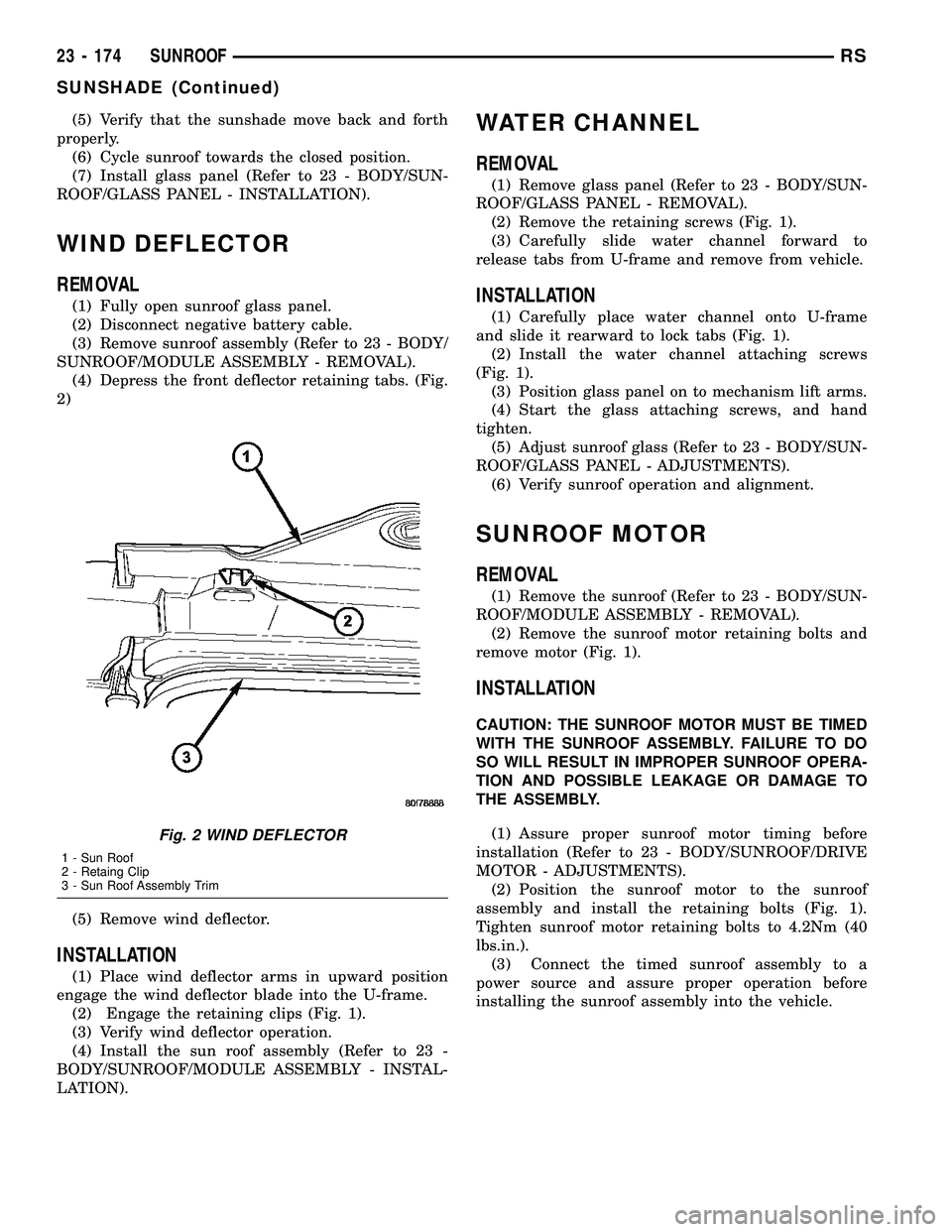
(4) Depress the front deflector retaining tabs. (Fig.
2)
(5) Remove wind deflector.
INSTALLATION
(1) Place wind deflector arms in upward position
engage the wind deflector blade into the U-frame.
(2) Engage the retaining clips (Fig. 1).
(3) Verify wind deflector operation.
(4) Install the sun roof assembly (Refer to 23 -
BODY/SUNROOF/MODULE ASSEMBLY - INSTAL-
LATION).
WATER CHANNEL
REMOVAL
(1) Remove glass panel (Refer to 23 - BODY/SUN-
ROOF/GLASS PANEL - REMOVAL).
(2) Remove the retaining screws (Fig. 1).
(3) Carefully slide water channel forward to
release tabs from U-frame and remove from vehicle.
INSTALLATION
(1) Carefully place water channel onto U-frame
and slide it rearward to lock tabs (Fig. 1).
(2) Install the water channel attaching screws
(Fig. 1).
(3) Position glass panel on to mechanism lift arms.
(4) Start the glass attaching screws, and hand
tighten.
(5) Adjust sunroof glass (Refer to 23 - BODY/SUN-
ROOF/GLASS PANEL - ADJUSTMENTS).
(6) Verify sunroof operation and alignment.
SUNROOF MOTOR
REMOVAL
(1) Remove the sunroof (Refer to 23 - BODY/SUN-
ROOF/MODULE ASSEMBLY - REMOVAL).
(2) Remove the sunroof motor retaining bolts and
remove motor (Fig. 1).
INSTALLATION
CAUTION: THE SUNROOF MOTOR MUST BE TIMED
WITH THE SUNROOF ASSEMBLY. FAILURE TO DO
SO WILL RESULT IN IMPROPER SUNROOF OPERA-
TION AND POSSIBLE LEAKAGE OR DAMAGE TO
THE ASSEMBLY.
(1) Assure proper sunroof motor timing before
installation (Refer to 23 - BODY/SUNROOF/DRIVE
MOTOR - ADJUSTMENTS).
(2) Position the sunroof motor to the sunroof
assembly and install the retaining bolts (Fig. 1).
Tighten sunroof motor retaining bolts to 4.2Nm (40
lbs.in.).
(3) Connect the timed sunroof assembly to a
power source and assure proper operation before
installing the sunroof assembly into the vehicle.
Fig. 2 WIND DEFLECTOR
1 - Sun Roof
2 - Retaing Clip
3 - Sun Roof Assembly Trim
23 - 174 SUNROOFRS
SUNSHADE (Continued)
Page 1955 of 2339
(5) Install the sunroof motor and verify proper
sunroof operation (Refer to 23 - BODY/SUNROOF/
DRIVE MOTOR - INSTALLATION).
(6) Install the sunroof glass, leaving the retaining
bolts loose.
(7) Install the sunroof assembly into the vehicle
(Refer to 23 - BODY/SUNROOF/MODULE ASSEM-
BLY - INSTALLATION).
(8) Flush the sunroof glass into the vehicle roof
opening and check sunroof glass alignment (Refer to
23 - BODY/SUNROOF/GLASS PANEL - ADJUST-
MENTS).
SUNROOF SWITCH
REMOVAL
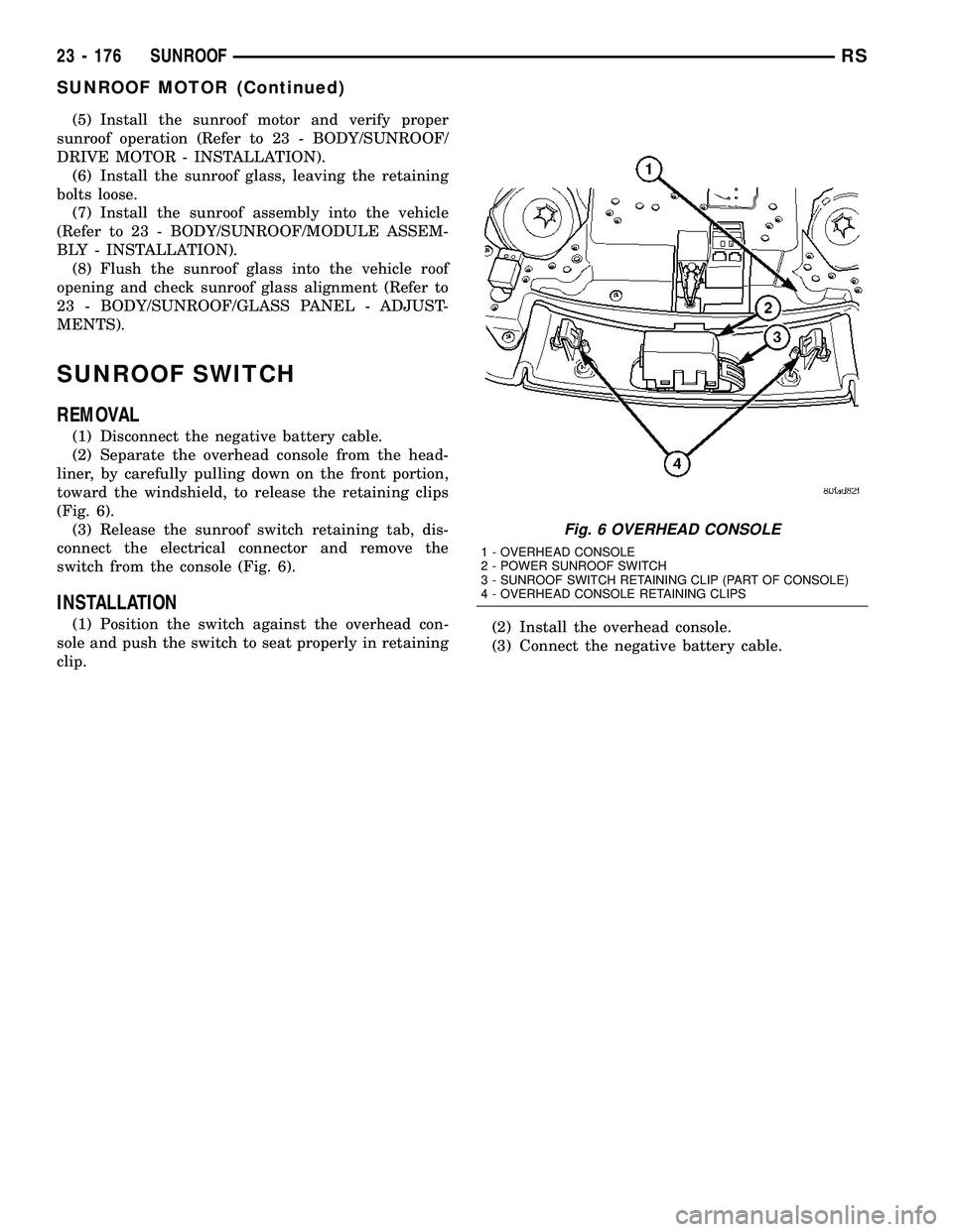
(1) Disconnect the negative battery cable.
(2) Separate the overhead console from the head-
liner, by carefully pulling down on the front portion,
toward the windshield, to release the retaining clips
(Fig. 6).
(3) Release the sunroof switch retaining tab, dis-
connect the electrical connector and remove the
switch from the console (Fig. 6).
INSTALLATION
(1) Position the switch against the overhead con-
sole and push the switch to seat properly in retaining
clip.(2) Install the overhead console.
(3) Connect the negative battery cable.
Fig. 6 OVERHEAD CONSOLE
1 - OVERHEAD CONSOLE
2 - POWER SUNROOF SWITCH
3 - SUNROOF SWITCH RETAINING CLIP (PART OF CONSOLE)
4 - OVERHEAD CONSOLE RETAINING CLIPS
23 - 176 SUNROOFRS
SUNROOF MOTOR (Continued)
Page 1962 of 2339
SEALER LOCATIONS
SPECIFICATIONS
SPECIFICATIONS - BODY SEALING LOCATIONS
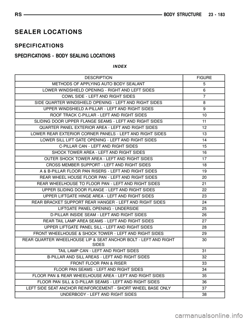
INDEX
DESCRIPTION FIGURE
METHODS OF APPLYING AUTO BODY SEALANT 5
LOWER WINDSHIELD OPENING - RIGHT AND LEFT SIDES 6
COWL SIDE - LEFT AND RIGHT SIDES 7
SIDE QUARTER WINDSHIELD OPENING - LEFT AND RIGHT SIDES 8
UPPER WINDSHIELD A-PILLAR - LEFT AND RIGHT SIDES 9
ROOF TRACK C-PILLAR - LEFT AND RIGHT SIDES 10
SLIDING DOOR UPPER FLANGE SEAMS - LEFT AND RIGHT SIDES 11
QUARTER PANEL EXTERIOR AREA - LEFT AND RIGHT SIDES 12
LOWER REAR EXTERIOR CORNER PANELS - LEFT AND RIGHT SIDES 13
LOWER SILL LIFT GATE OPENING - LEFT AND RIGHT SIDES 14
C-PILLAR CAN - LEFT AND RIGHT SIDES 15
SHOCK TOWER AREA - LEFT AND RIGHT SIDES 16
OUTER SHOCK TOWER AREA - LEFT AND RIGHT SIDES 17
CROSS MEMBER SUPPORT - LEFT AND RIGHT SIDES 18
A & B-PILLAR FLOOR PAN RISERS - LEFT AND RIGHT SIDES 19
REAR WHEEL HOUSE FLOOR PAN - LEFT AND RIGHT SIDES 20
REAR WHEELHOUSE TO FLOOR PAN - LEFT AND RIGHT SIDES 21
UPPER SLIDING DOOR FLANGE - LEFT AND RIGHT SIDES 22
UPPER LIFTGATE HINGE AREA - LEFT AND RIGHT SIDES 23
REAR BRACKET SUPPORT REAR HANGER - LEFT AND RIGHT SIDES 24
LIFTGATE PANEL OPENING - UNDERSIDE 25
D-PILLAR INSIDE SEAM - LEFT AND RIGHT SIDES 26
REAR TAIL LAMP AREA SEAMS - LEFT AND RIGHT SIDES 27
UPPER LIFTGATE PANEL SILL - LEFT AND RIGHT SIDES 28
FRONT WHEELHOUSE & SHOCK TOWER - LEFT AND RIGHT SIDES 29
REAR QUARTER WHEELHOUSE LIP & SEAT ANCHOR BOLT - LEFT AND RIGHT
SIDES30
TAIL LAMP CAN - LEFT AND RIGHT SIDES 31
B-PILLAR AND SILL AREAS - LEFT AND RIGHT SIDES 32
FRONT FLOOR PAN & RISER 33
FLOOR PAN SEAMS - LEFT AND RIGHT SIDES 34
FLOOR PAN & REAR WHEELHOUSE AREA - LEFT AND RIGHT SIDES 35
FLOOR PAN SILL & D-PILLAR SEAMS - LEFT AND RIGHT SIDES 36
LEFT SIDE SEAT ANCHOR REINFORCEMENT - SHORT WHEEL BASE ONLY 37
UNDERBODY - LEFT AND RIGHT SIDES 38
RSBODY STRUCTURE23 - 183
Page 1970 of 2339
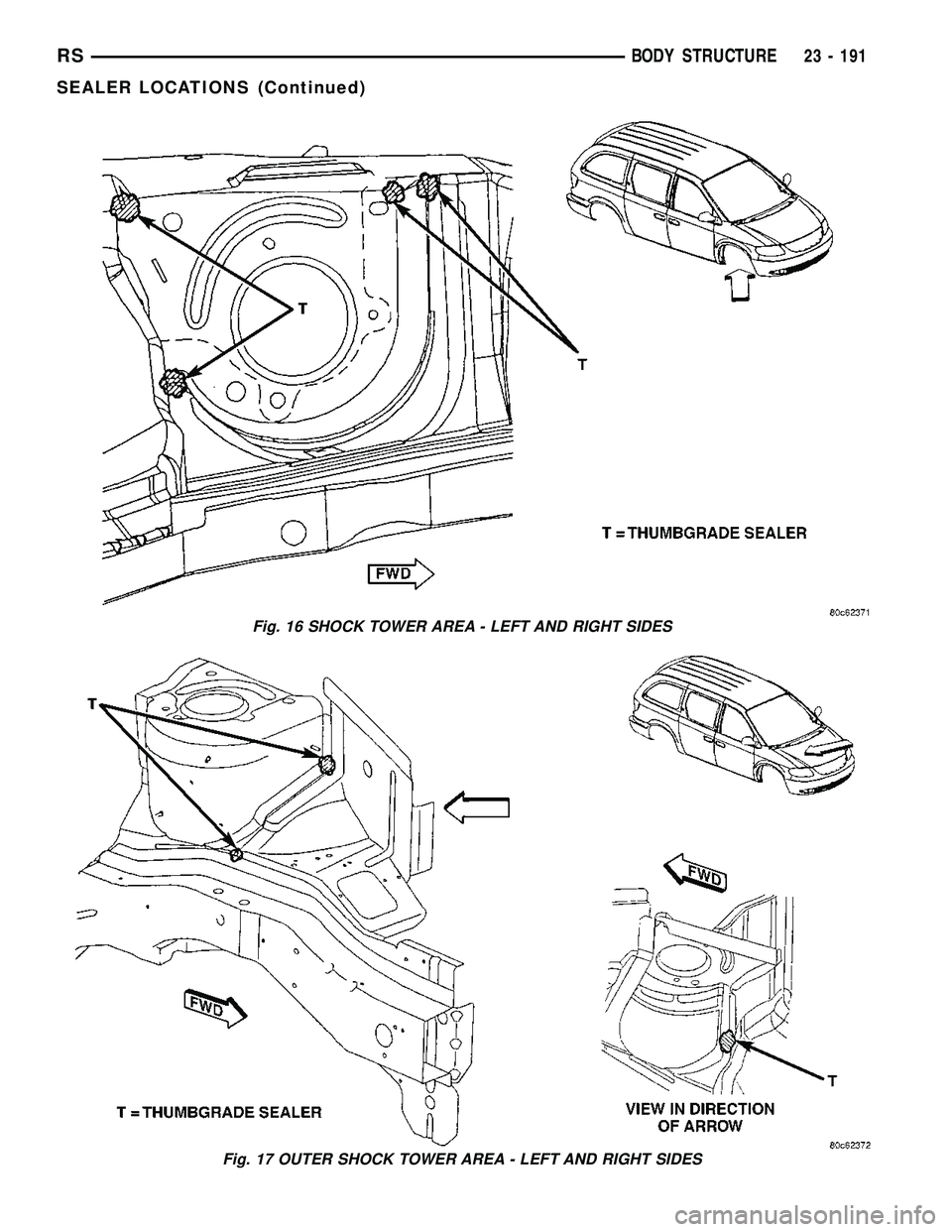
Fig. 16 SHOCK TOWER AREA - LEFT AND RIGHT SIDES
Fig. 17 OUTER SHOCK TOWER AREA - LEFT AND RIGHT SIDES
RSBODY STRUCTURE23 - 191
SEALER LOCATIONS (Continued)
Page 1976 of 2339
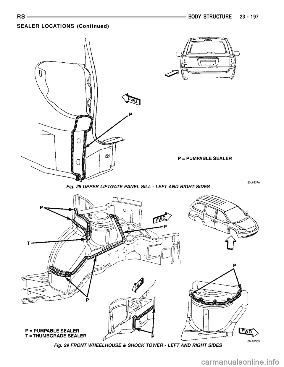
Fig. 28 UPPER LIFTGATE PANEL SILL - LEFT AND RIGHT SIDES
Fig. 29 FRONT WHEELHOUSE & SHOCK TOWER - LEFT AND RIGHT SIDES
RSBODY STRUCTURE23 - 197
SEALER LOCATIONS (Continued)