2005 CHRYSLER CARAVAN door lock
[x] Cancel search: door lockPage 1860 of 2339
CARPETS AND FLOOR MATS
REMOVAL
(1) Remove front seats. (Refer to 23 - BODY/
SEATS/SEAT - REMOVAL)
(2) Remove front center console.
(3) Remove heel blocker (plastic block below accel-
erator pedal).
(4) Remove the remaining seats. Refer to the Own-
er's Manual for the proper procedures.
(5) Remove front cowl panels and sill plates.
(6) Remove sliding door sill plates. (Refer to 23 -
BODY/INTERIOR/SLIDING DOOR SILL PLATE -
REMOVAL)
(7) Remove the cargo organizer, if equipped.
(8) Remove liftgate scuff plate. (Refer to 23 -
BODY/INTERIOR/LIFTGATE SCUFF PLATE -
REMOVAL)
(9) Remove lower B-pillar trim covers.
(10) Remove D-pillar trim covers.
(11) Remove Quarter trim panels.
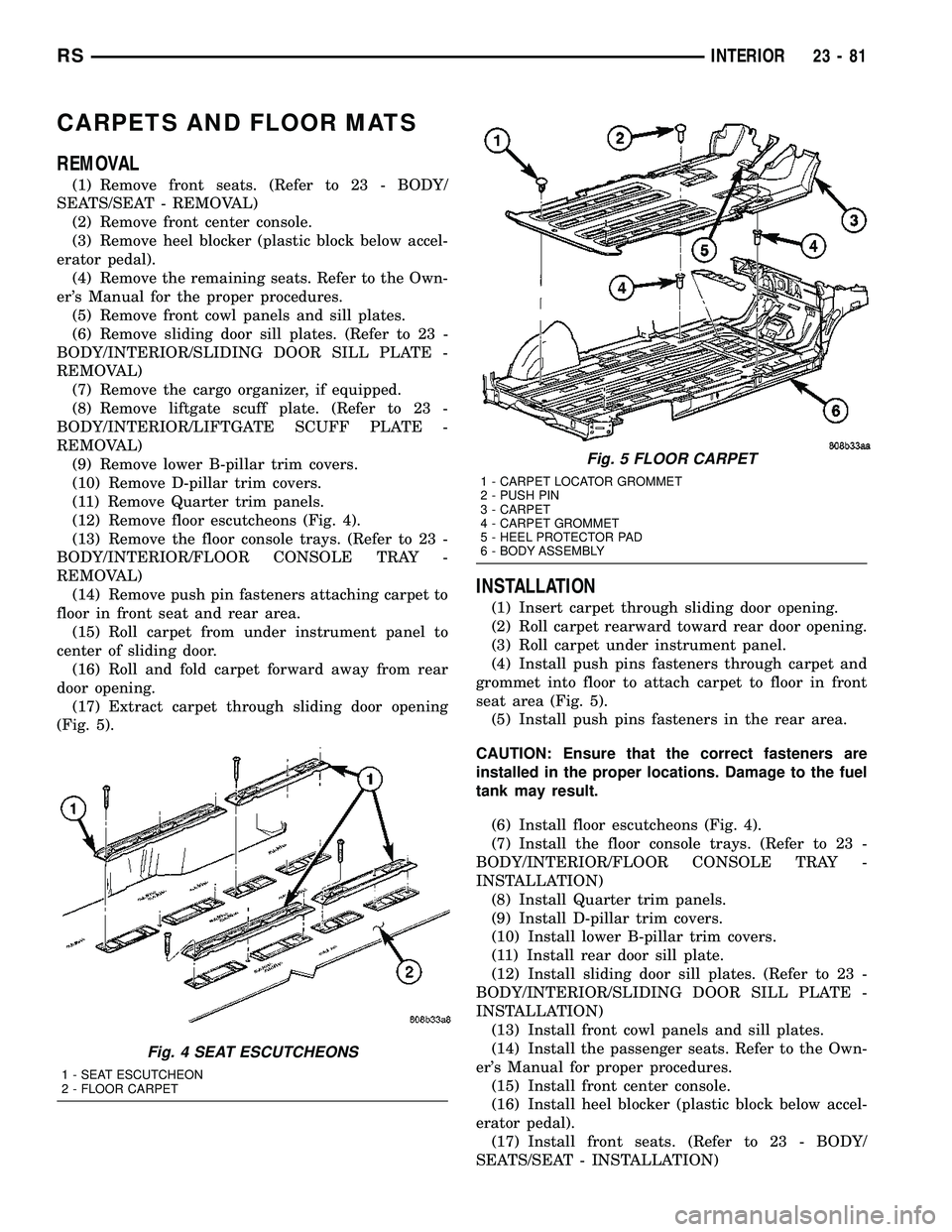
(12) Remove floor escutcheons (Fig. 4).
(13) Remove the floor console trays. (Refer to 23 -
BODY/INTERIOR/FLOOR CONSOLE TRAY -
REMOVAL)
(14) Remove push pin fasteners attaching carpet to
floor in front seat and rear area.
(15) Roll carpet from under instrument panel to
center of sliding door.
(16) Roll and fold carpet forward away from rear
door opening.
(17) Extract carpet through sliding door opening
(Fig. 5).
INSTALLATION
(1) Insert carpet through sliding door opening.
(2) Roll carpet rearward toward rear door opening.
(3) Roll carpet under instrument panel.
(4) Install push pins fasteners through carpet and
grommet into floor to attach carpet to floor in front
seat area (Fig. 5).
(5) Install push pins fasteners in the rear area.
CAUTION: Ensure that the correct fasteners are
installed in the proper locations. Damage to the fuel
tank may result.
(6) Install floor escutcheons (Fig. 4).
(7) Install the floor console trays. (Refer to 23 -
BODY/INTERIOR/FLOOR CONSOLE TRAY -
INSTALLATION)
(8) Install Quarter trim panels.
(9) Install D-pillar trim covers.
(10) Install lower B-pillar trim covers.
(11) Install rear door sill plate.
(12) Install sliding door sill plates. (Refer to 23 -
BODY/INTERIOR/SLIDING DOOR SILL PLATE -
INSTALLATION)
(13) Install front cowl panels and sill plates.
(14) Install the passenger seats. Refer to the Own-
er's Manual for proper procedures.
(15) Install front center console.
(16) Install heel blocker (plastic block below accel-
erator pedal).
(17) Install front seats. (Refer to 23 - BODY/
SEATS/SEAT - INSTALLATION)
Fig. 4 SEAT ESCUTCHEONS
1 - SEAT ESCUTCHEON
2 - FLOOR CARPET
Fig. 5 FLOOR CARPET
1 - CARPET LOCATOR GROMMET
2 - PUSH PIN
3 - CARPET
4 - CARPET GROMMET
5 - HEEL PROTECTOR PAD
6 - BODY ASSEMBLY
RSINTERIOR23-81
Page 1863 of 2339
(3) Roll carpet forward under instrument panel
(Fig. 8).
(4) Install push pins fasteners through carpet and
grommet into floor to attach carpet to floor in front
seat area.
(5) Pull wire harnesses through the carpet as
needed.
(6) Smooth out the carpet and allowing weld studs
to go all the way through the carpet.
(7) Install rear push pins fasteners attaching rear
of carpet.
(8) Place third row carpet cover into position and
press clips into position (Fig. 9).
(9) Slide the carpet under the quarter trim panel
into position.
(10) Install lower B-pillar trim covers.
(11) Install sliding door sill plates. (Refer to 23 -
BODY/INTERIOR/SLIDING DOOR SILL PLATE -
INSTALLATION).
(12) Install front carpet trim ring and cover (Fig.
7). (Refer to 23 - BODY/INTERIOR/CARPETS TRIM
RING AND COVER - INSTALLATION)
(13) Install seat belt anchors at the passenger side
B-pillar and driver side C-pillars
(14) Install kick plate and heel pad at the gas
pedal
(15) Install winch plug (spare tire winch) (Fig. 6).
(16) Install front cowl panels and sill plates.
(17) Install heel blocker (plastic block below accel-
erator pedal).
(18) Install the floor console base tray and discon-
nect wire connector from the base tray. (Refer to 23 -
BODY/INTERIOR/FLOOR CONSOLE BASE TRAY -
INSTALLATION).
(19) Install instrument panel lower console. (Refer
to 23 - BODY/INSTRUMENT PANEL/STORAGE
BIN - INSTALLATION).
(20) Install front seats. (Refer to 23 - BODY/
SEATS/SEAT - REMOVAL).
(21) Install floor mats.CARPET TRIM RING AND
COVER - FOLD-IN-FLOOR
REMOVAL
(1) Move front seats to the full forward position.
(2) Fold the second row seats into the floor.
(3) Remove the load floor plugs (Fig. 10).
(4) Remove the ten weld nuts.
(5) Open door covers (Fig. 11).
(6) Remove the four inter weld nuts (Fig. 12).
(7) Raise the front trim ring and cover up off of
the weld studs and remove from vehicle.
INSTALLATION
(1) Place front trim ring and cover assembly into
position.
(2) Open door covers (Fig. 11).
(3) Install the four inter weld nuts (Fig. 12).
(4) Close door covers.
(5) Install the ten weld nuts (Fig. 10).
(6) Install the eight load floor plugs.
(7) Open the second row seats into position.
(8) Move front seats to the position.
23 - 84 INTERIORRS
CARPETS - FOLD-IN-FLOOR (Continued)
Page 1868 of 2339
DOOR SILL TRIM PLATE
REMOVAL
(1) Using trim stick (C-4755), disengage hidden
clips holding door sill plate from door sill.
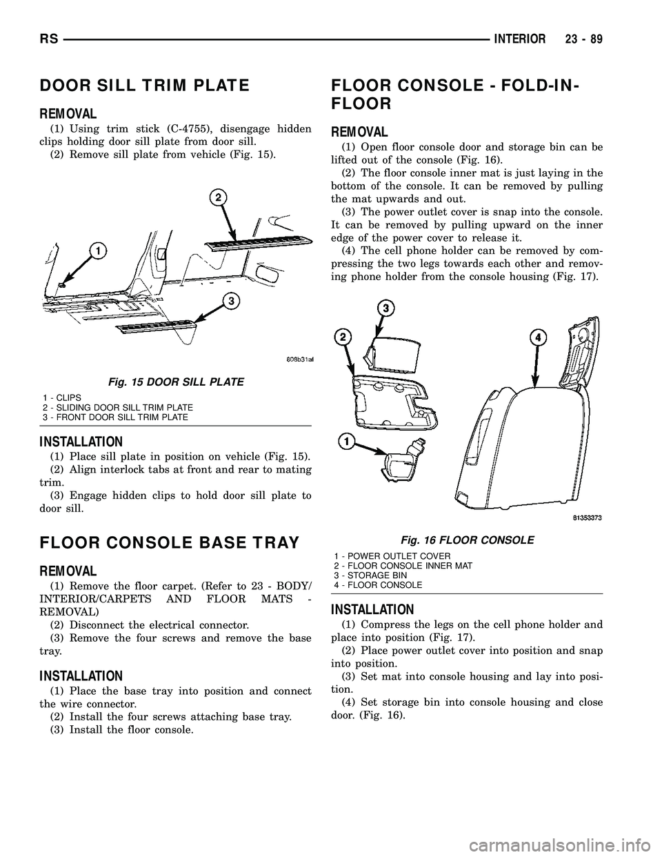
(2) Remove sill plate from vehicle (Fig. 15).
INSTALLATION
(1) Place sill plate in position on vehicle (Fig. 15).
(2) Align interlock tabs at front and rear to mating
trim.
(3) Engage hidden clips to hold door sill plate to
door sill.
FLOOR CONSOLE BASE TRAY
REMOVAL
(1) Remove the floor carpet. (Refer to 23 - BODY/
INTERIOR/CARPETS AND FLOOR MATS -
REMOVAL)
(2) Disconnect the electrical connector.
(3) Remove the four screws and remove the base
tray.
INSTALLATION
(1) Place the base tray into position and connect
the wire connector.
(2) Install the four screws attaching base tray.
(3) Install the floor console.
FLOOR CONSOLE - FOLD-IN-
FLOOR
REMOVAL
(1) Open floor console door and storage bin can be
lifted out of the console (Fig. 16).
(2) The floor console inner mat is just laying in the
bottom of the console. It can be removed by pulling
the mat upwards and out.
(3) The power outlet cover is snap into the console.
It can be removed by pulling upward on the inner
edge of the power cover to release it.
(4) The cell phone holder can be removed by com-
pressing the two legs towards each other and remov-
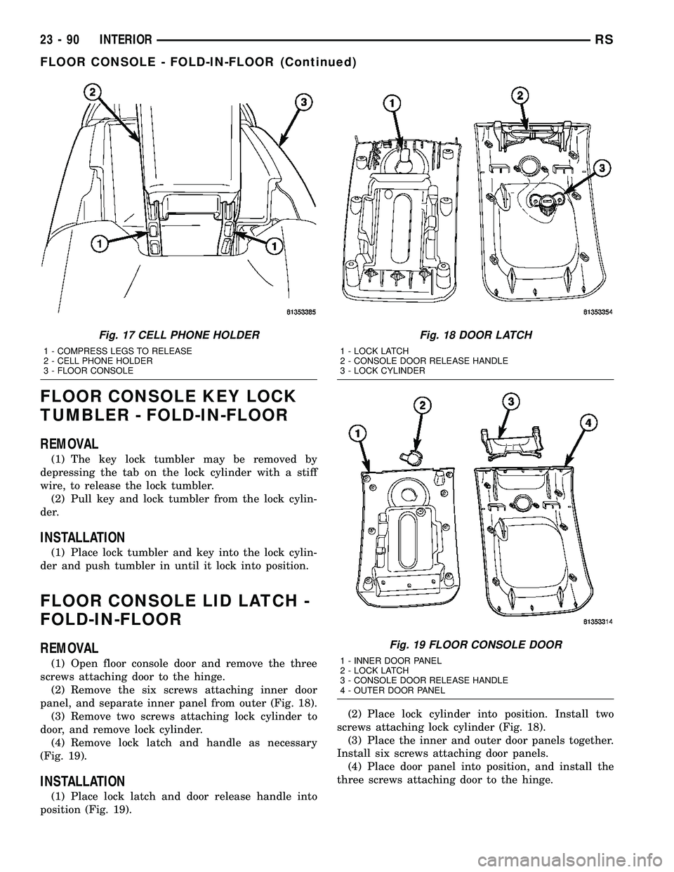
ing phone holder from the console housing (Fig. 17).
INSTALLATION
(1) Compress the legs on the cell phone holder and
place into position (Fig. 17).
(2) Place power outlet cover into position and snap
into position.
(3) Set mat into console housing and lay into posi-
tion.
(4) Set storage bin into console housing and close
door. (Fig. 16).
Fig. 15 DOOR SILL PLATE
1 - CLIPS
2 - SLIDING DOOR SILL TRIM PLATE
3 - FRONT DOOR SILL TRIM PLATE
Fig. 16 FLOOR CONSOLE
1 - POWER OUTLET COVER
2 - FLOOR CONSOLE INNER MAT
3 - STORAGE BIN
4 - FLOOR CONSOLE
RSINTERIOR23-89
Page 1869 of 2339
FLOOR CONSOLE KEY LOCK
TUMBLER - FOLD-IN-FLOOR
REMOVAL
(1) The key lock tumbler may be removed by
depressing the tab on the lock cylinder with a stiff
wire, to release the lock tumbler.
(2) Pull key and lock tumbler from the lock cylin-
der.
INSTALLATION
(1) Place lock tumbler and key into the lock cylin-
der and push tumbler in until it lock into position.
FLOOR CONSOLE LID LATCH -
FOLD-IN-FLOOR
REMOVAL
(1) Open floor console door and remove the three
screws attaching door to the hinge.
(2) Remove the six screws attaching inner door
panel, and separate inner panel from outer (Fig. 18).
(3) Remove two screws attaching lock cylinder to
door, and remove lock cylinder.
(4) Remove lock latch and handle as necessary
(Fig. 19).
INSTALLATION
(1) Place lock latch and door release handle into
position (Fig. 19).(2) Place lock cylinder into position. Install two
screws attaching lock cylinder (Fig. 18).
(3) Place the inner and outer door panels together.
Install six screws attaching door panels.
(4) Place door panel into position, and install the
three screws attaching door to the hinge.
Fig. 17 CELL PHONE HOLDER
1 - COMPRESS LEGS TO RELEASE
2 - CELL PHONE HOLDER
3 - FLOOR CONSOLE
Fig. 18 DOOR LATCH
1 - LOCK LATCH
2 - CONSOLE DOOR RELEASE HANDLE
3 - LOCK CYLINDER
Fig. 19 FLOOR CONSOLE DOOR
1 - INNER DOOR PANEL
2 - LOCK LATCH
3 - CONSOLE DOOR RELEASE HANDLE
4 - OUTER DOOR PANEL
23 - 90 INTERIORRS
FLOOR CONSOLE - FOLD-IN-FLOOR (Continued)
Page 1870 of 2339
HEADLINER
REMOVAL
(1) Remove sun visors and vanity mirrors.
(2) Remove sun visor center supports.
(3) If equipped, remove coat hooks.
(4) If equipped, remove roof rail modules.
(5) Remove A-pillar trim covers. (Refer to 23 -
BODY/INTERIOR/A-PILLAR TRIM - REMOVAL).
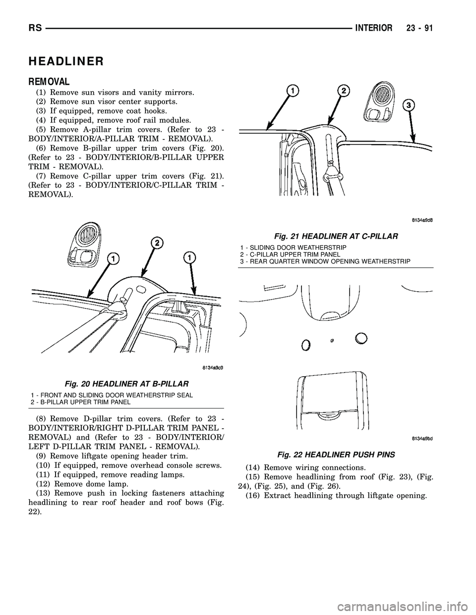
(6) Remove B-pillar upper trim covers (Fig. 20).
(Refer to 23 - BODY/INTERIOR/B-PILLAR UPPER
TRIM - REMOVAL).
(7) Remove C-pillar upper trim covers (Fig. 21).
(Refer to 23 - BODY/INTERIOR/C-PILLAR TRIM -
REMOVAL).
(8) Remove D-pillar trim covers. (Refer to 23 -
BODY/INTERIOR/RIGHT D-PILLAR TRIM PANEL -
REMOVAL) and (Refer to 23 - BODY/INTERIOR/
LEFT D-PILLAR TRIM PANEL - REMOVAL).
(9) Remove liftgate opening header trim.
(10) If equipped, remove overhead console screws.
(11) If equipped, remove reading lamps.
(12) Remove dome lamp.
(13) Remove push in locking fasteners attaching
headlining to rear roof header and roof bows (Fig.
22).(14) Remove wiring connections.
(15) Remove headlining from roof (Fig. 23), (Fig.
24), (Fig. 25), and (Fig. 26).
(16) Extract headlining through liftgate opening.
Fig. 20 HEADLINER AT B-PILLAR
1 - FRONT AND SLIDING DOOR WEATHERSTRIP SEAL
2 - B-PILLAR UPPER TRIM PANEL
Fig. 21 HEADLINER AT C-PILLAR
1 - SLIDING DOOR WEATHERSTRIP
2 - C-PILLAR UPPER TRIM PANEL
3 - REAR QUARTER WINDOW OPENING WEATHERSTRIP
Fig. 22 HEADLINER PUSH PINS
RSINTERIOR23-91
Page 1878 of 2339
INSTALLATION
(1) Place sill plate in position on vehicle.
(2) Engage hooks to hold outside edge of sill plate
to door sill.
(3) Align guide pins to holes in door sill.
(4) Engage hidden clips to hold sill plate to sliding
door opening sill.
(5) Engage interlock tabs at lower B-pillar and
quarter trim panel.
SUN VISOR
REMOVAL
All vehicles with driver and passenger side air
bags must have a colored coded five Bullet point air
bag warning label applied to the sun visor, verify
label availability and ensure the label is installed.
(1) Disengage sun visor from center support.
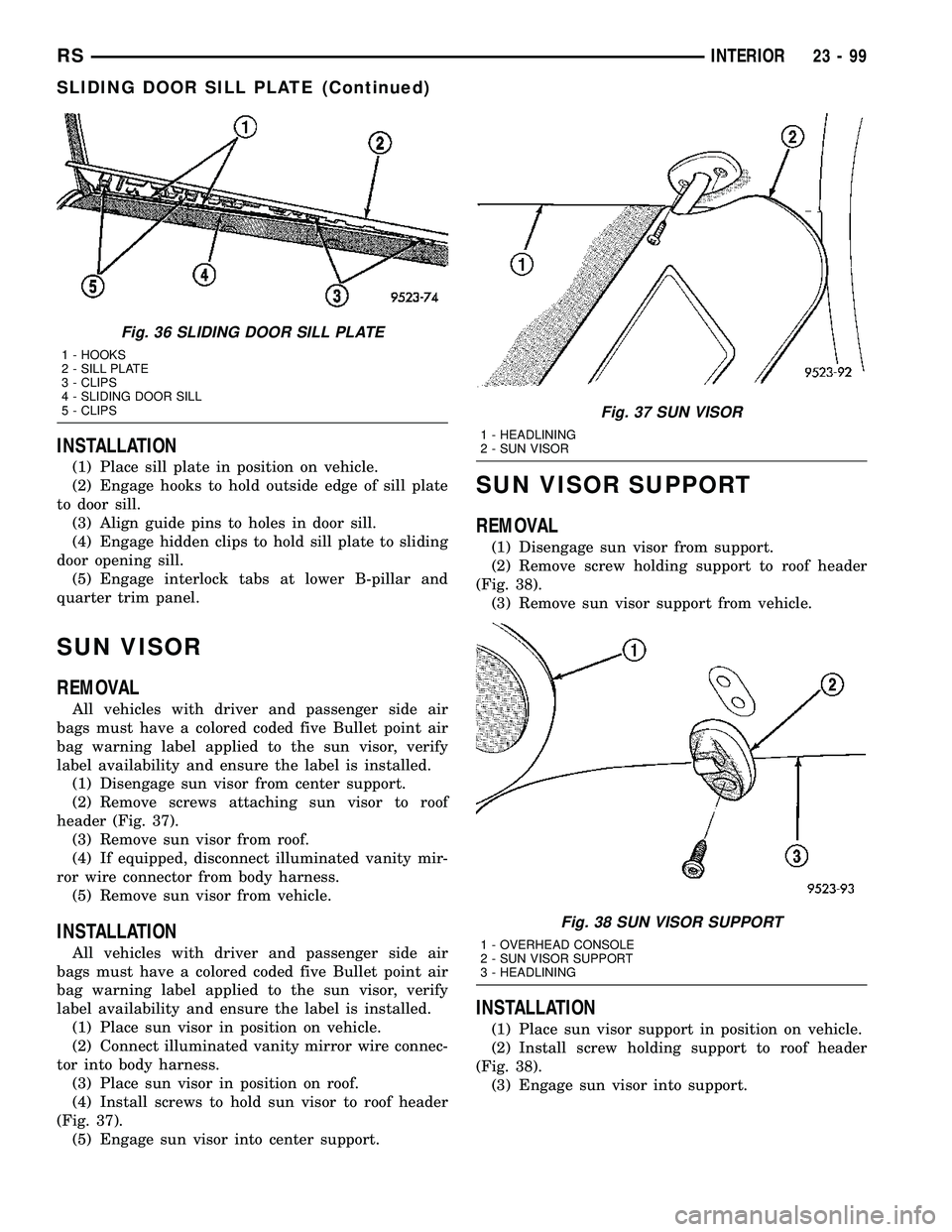
(2) Remove screws attaching sun visor to roof
header (Fig. 37).
(3) Remove sun visor from roof.
(4) If equipped, disconnect illuminated vanity mir-
ror wire connector from body harness.
(5) Remove sun visor from vehicle.
INSTALLATION
All vehicles with driver and passenger side air
bags must have a colored coded five Bullet point air
bag warning label applied to the sun visor, verify
label availability and ensure the label is installed.
(1) Place sun visor in position on vehicle.
(2) Connect illuminated vanity mirror wire connec-
tor into body harness.
(3) Place sun visor in position on roof.
(4) Install screws to hold sun visor to roof header
(Fig. 37).
(5) Engage sun visor into center support.
SUN VISOR SUPPORT
REMOVAL
(1) Disengage sun visor from support.
(2) Remove screw holding support to roof header
(Fig. 38).
(3) Remove sun visor support from vehicle.
INSTALLATION
(1) Place sun visor support in position on vehicle.
(2) Install screw holding support to roof header
(Fig. 38).
(3) Engage sun visor into support.
Fig. 36 SLIDING DOOR SILL PLATE
1 - HOOKS
2 - SILL PLATE
3 - CLIPS
4 - SLIDING DOOR SILL
5 - CLIPS
Fig. 37 SUN VISOR
1 - HEADLINING
2 - SUN VISOR
Fig. 38 SUN VISOR SUPPORT
1 - OVERHEAD CONSOLE
2 - SUN VISOR SUPPORT
3 - HEADLINING
RSINTERIOR23-99
SLIDING DOOR SILL PLATE (Continued)
Page 1941 of 2339
(4) Remove A-pillar trim panels.
(5) Place protective covers over instrument panel
and hood.
(6) Remove windshield molding. Using pliers, pull
outward on molding at the bottom of A-pillars.
(7) Using a sharp cold knife, cut urethane adhe-
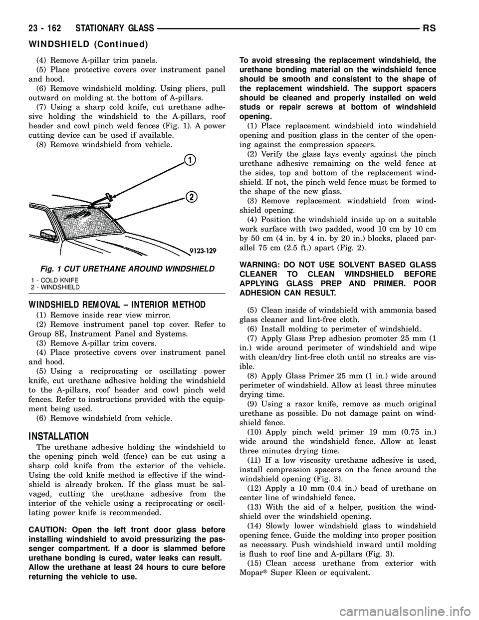
sive holding the windshield to the A-pillars, roof
header and cowl pinch weld fences (Fig. 1). A power
cutting device can be used if available.
(8) Remove windshield from vehicle.
WINDSHIELD REMOVAL ± INTERIOR METHOD
(1) Remove inside rear view mirror.
(2) Remove instrument panel top cover. Refer to
Group 8E, Instrument Panel and Systems.
(3) Remove A-pillar trim covers.
(4) Place protective covers over instrument panel
and hood.
(5) Using a reciprocating or oscillating power
knife, cut urethane adhesive holding the windshield
to the A-pillars, roof header and cowl pinch weld
fences. Refer to instructions provided with the equip-
ment being used.
(6) Remove windshield from vehicle.
INSTALLATION
The urethane adhesive holding the windshield to
the opening pinch weld (fence) can be cut using a
sharp cold knife from the exterior of the vehicle.
Using the cold knife method is effective if the wind-
shield is already broken. If the glass must be sal-
vaged, cutting the urethane adhesive from the
interior of the vehicle using a reciprocating or oscil-
lating power knife is recommended.
CAUTION: Open the left front door glass before
installing windshield to avoid pressurizing the pas-
senger compartment. If a door is slammed before
urethane bonding is cured, water leaks can result.
Allow the urethane at least 24 hours to cure before
returning the vehicle to use.To avoid stressing the replacement windshield, the
urethane bonding material on the windshield fence
should be smooth and consistent to the shape of
the replacement windshield. The support spacers
should be cleaned and properly installed on weld
studs or repair screws at bottom of windshield
opening.
(1) Place replacement windshield into windshield
opening and position glass in the center of the open-
ing against the compression spacers.
(2) Verify the glass lays evenly against the pinch
urethane adhesive remaining on the weld fence at
the sides, top and bottom of the replacement wind-
shield. If not, the pinch weld fence must be formed to
the shape of the new glass.
(3) Remove replacement windshield from wind-
shield opening.
(4) Position the windshield inside up on a suitable
work surface with two padded, wood 10 cm by 10 cm
by 50 cm (4 in. by 4 in. by 20 in.) blocks, placed par-
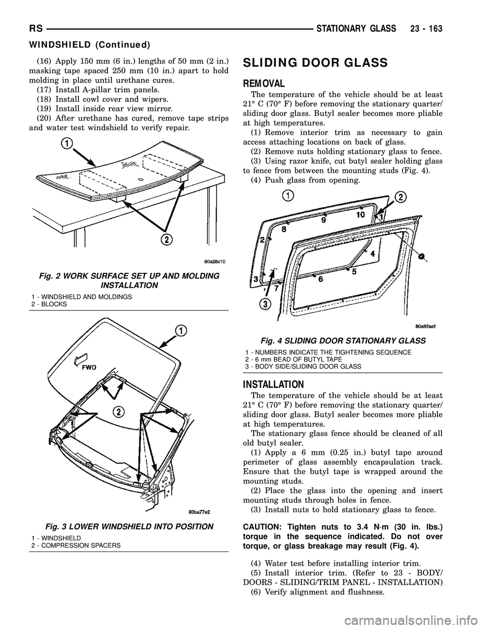
allel 75 cm (2.5 ft.) apart (Fig. 2).
WARNING: DO NOT USE SOLVENT BASED GLASS
CLEANER TO CLEAN WINDSHIELD BEFORE
APPLYING GLASS PREP AND PRIMER. POOR
ADHESION CAN RESULT.
(5) Clean inside of windshield with ammonia based
glass cleaner and lint-free cloth.
(6) Install molding to perimeter of windshield.
(7) Apply Glass Prep adhesion promoter 25 mm (1
in.) wide around perimeter of windshield and wipe
with clean/dry lint-free cloth until no streaks are vis-
ible.
(8) Apply Glass Primer 25 mm (1 in.) wide around
perimeter of windshield. Allow at least three minutes
drying time.
(9) Using a razor knife, remove as much original
urethane as possible. Do not damage paint on wind-
shield fence.
(10) Apply pinch weld primer 19 mm (0.75 in.)
wide around the windshield fence. Allow at least
three minutes drying time.
(11) If a low viscosity urethane adhesive is used,
install compression spacers on the fence around the
windshield opening (Fig. 3).
(12) Apply a 10 mm (0.4 in.) bead of urethane on
center line of windshield fence.
(13) With the aid of a helper, position the wind-
shield over the windshield opening.
(14) Slowly lower windshield glass to windshield
opening fence. Guide the molding into proper position
as necessary. Push windshield inward until molding
is flush to roof line and A-pillars (Fig. 3).
(15) Clean access urethane from exterior with
MopartSuper Kleen or equivalent.
Fig. 1 CUT URETHANE AROUND WINDSHIELD
1 - COLD KNIFE
2 - WINDSHIELD
23 - 162 STATIONARY GLASSRS
WINDSHIELD (Continued)
Page 1942 of 2339
(16) Apply 150 mm (6 in.) lengths of 50 mm (2 in.)
masking tape spaced 250 mm (10 in.) apart to hold
molding in place until urethane cures.
(17) Install A-pillar trim panels.
(18) Install cowl cover and wipers.
(19) Install inside rear view mirror.
(20) After urethane has cured, remove tape strips
and water test windshield to verify repair.SLIDING DOOR GLASS
REMOVAL
The temperature of the vehicle should be at least
21É C (70É F) before removing the stationary quarter/
sliding door glass. Butyl sealer becomes more pliable
at high temperatures.
(1) Remove interior trim as necessary to gain
access attaching locations on back of glass.
(2) Remove nuts holding stationary glass to fence.
(3)
Using razor knife, cut butyl sealer holding glass
to fence from between the mounting studs (Fig. 4).
(4) Push glass from opening.
INSTALLATION
The temperature of the vehicle should be at least
21É C (70É F) before removing the stationary quarter/
sliding door glass. Butyl sealer becomes more pliable
at high temperatures.
The stationary glass fence should be cleaned of all
old butyl sealer.
(1) Applya6mm(0.25 in.) butyl tape around
perimeter of glass assembly encapsulation track.
Ensure that the butyl tape is wrapped around the
mounting studs.
(2) Place the glass into the opening and insert
mounting studs through holes in fence.
(3) Install nuts to hold stationary glass to fence.
CAUTION: Tighten nuts to 3.4 N´m (30 in. lbs.)
torque in the sequence indicated. Do not over
torque, or glass breakage may result (Fig. 4).
(4) Water test before installing interior trim.
(5) Install interior trim. (Refer to 23 - BODY/
DOORS - SLIDING/TRIM PANEL - INSTALLATION)
(6) Verify alignment and flushness.
Fig. 2 WORK SURFACE SET UP AND MOLDING
INSTALLATION
1 - WINDSHIELD AND MOLDINGS
2 - BLOCKS
Fig. 3 LOWER WINDSHIELD INTO POSITION
1 - WINDSHIELD
2 - COMPRESSION SPACERS
Fig. 4 SLIDING DOOR STATIONARY GLASS
1 - NUMBERS INDICATE THE TIGHTENING SEQUENCE
2-6mmBEAD OF BUTYL TAPE
3 - BODY SIDE/SLIDING DOOR GLASS
RSSTATIONARY GLASS23 - 163
WINDSHIELD (Continued)