2005 CHRYSLER CARAVAN seat belt
[x] Cancel search: seat beltPage 1946 of 2339

(6) Install fully the entire A-pillar glass run sec-
tion by indexing the molded corner detail into the
roll frame. Slide the glass run up the A-pillar until
the rubber molded joint just touches the roll frame.
(7) Verify that the tertiary seal is on the correct
side of the roll frame prior to seating the glass run
fully onto the frame. Verify the glass runs is fully
seated for the header, and A-pillar and B-pillar
(8) Install screw attaching glass run weatherstrip
to inner door panel.
(9) Install inner belt weatherstrip.
(10) Install watershed.
(11) Push weatherstrip groove onto lip along top of
door frame.
(12) Engage clip into slot in door frame.
(13) Push weatherstrip into channel at rear of door
frame, working from the top to bottom.
(14) Install door frame closeout moldings.
(15) Install door speaker, if equipped.
(16) Install door trim panel.FRONT DOOR OUTER BELT
MOLDING
REMOVAL
(1) Remove the side view mirror. (Refer to 23 -
BODY/EXTERIOR/SIDE VIEW MIRROR -
REMOVAL)
(2) Remove door trim panel.
(3) Roll door glass down.
(4) Using a hook tool, disengage interlocking lip at
the base of the inward edge of the belt molding (Fig.
1).
(5) Remove belt molding from door.
INSTALLATION
(1) Place belt molding in position on door (Fig. 1).
NOTE: Make sure end of applique is against outer
belt.
(2) Engage interlocking lip at the base of the
inward edge of the belt molding on door panel.
(3) Install door trim panel.
Fig. 1 FRONT DOOR WEATHERSTRIP
1 - DOOR GLASS RUN WEATHERSTRIP
2 - FRONT INNER DOOR
3 - DOOR BELT OUTER WEATHERSTRIP4 - DOOR MOUNTED WEATHERSTRIP
5 - DOOR OUTER BELT WEATHERSTRIP
RSWEATHERSTRIP/SEALS23 - 167
FRONT DOOR GLASS RUN WEATHERSTRIP (Continued)
Page 1951 of 2339
SYMPTOM POSSIBLE CAUSE
Sunshade will not function or does not
operate smoothlySunshade feet are missing, broken or loose.
No lubracation in track.
Track obstructions or interference.
Glass movement not consistant or glass does
not operate smoothlyGlass and Track timing.
Glass and Track alignment
Cables and Guide alignment
WATER DRAINAGE AND WIND NOISE DIAGNOSIS
The sliding glass panel is designed to seal water
entry with a snug fit between the roof and the seal.
The fit can be checked by inserting a piece of paper
between the roof and the seal. The piece of paper
should have some resistance when pulled out when
the glass panel is in the closed position. Excessive
wind noise could result if the gap clearances are
exceeded. The sunroof glass panel may need to be
adjusted. Refer to Sunroof Glass Panel Adjustment
for proper procedures.
Adequate drainage is provided by a drain trough in
the sunroof housing which encircles the sliding glass
panel and leads to drain hoses. If a wet headliner or
other water leak complaints are encountered, before
performing any adjustments, first ensure that the
drainage system is not plugged or disconnected. Use
a pint container to pour water into the sunroof hous-
ing drain trough. If water flow is restricted in any of
the four drain holes, use compressed air to blow out
any material plugging the drain system. Retest sys-
tem again.
To further check for a disconnected drain hose:
(1) Remove A-pillar trim, sun visors, and map
lamps/mini console.
(2) Remove sunroof opening trim lace. Refer to
Sunroof Opening Trim Lace.
NOTE: Care must be taken not to fold or kink the
headliner upon removal.
(3) Lower headliner as necessary to gain access to
sunroof housing drain tubes. Refer to Headlining
Removal and Installation for proper procedures.
(4) Repair as necessary.
DRAIN TUBE
REMOVAL
FRONT HOSES
NOTE: Front A-pillars are filled with sound deaden-
ing foam and the front drain tubes are sealed into
the pillars.
(1) Move glass panel to the fully closed position.
(2) Disconnect negative battery cable.
(3) Remove headliner (Refer to 23 - BODY/INTE-
RIOR/HEADLINER - REMOVAL).
(4) Disconnect the drain hose from the sunroof
housing (Fig. 1).
(5) Drain any liquid from hose connection, repair
as necessary.
REAR HOUSING HOSE
(1) Move glass panel to the fully closed position.
(2) Disconnect negative battery cable.
(3) Remove headliner (Refer to 23 - BODY/INTE-
RIOR/HEADLINER - REMOVAL).
(4) Remove third seat or seats from vehicle.
(5) Remove second seat belt lower anchor.
(6) Remove third seat lower anchor.
(7) Remove quarter trim bolster.
(8) Remove trim panel screws.
(9) Remove quarter trim panel
(10) Disconnect the drain hose from the sunroof
housing. (Fig. 1).
(11) Drain any liquid from hose connection, if nec-
essary, and remove tube.
INSTALLATION
FRONT HOSES
(1) Connect the new drain hose to the sunroof
housing and test drainage (Fig. 1).
(2) Install headliner (Refer to 23 - BODY/INTERI-
OR/HEADLINER - INSTALLATION).
(3) Install sunroof opening trim lace.
(4) Connect the control switch wire connector and
install control switch.
23 - 172 SUNROOFRS
SUNROOF (Continued)
Page 2014 of 2339
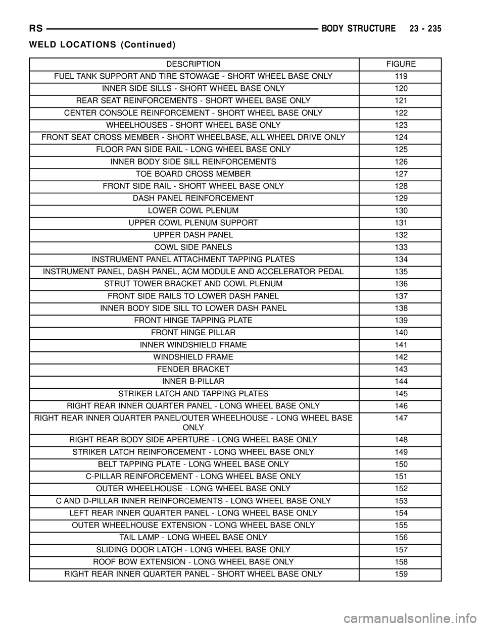
DESCRIPTION FIGURE
FUEL TANK SUPPORT AND TIRE STOWAGE - SHORT WHEEL BASE ONLY 119
INNER SIDE SILLS - SHORT WHEEL BASE ONLY 120
REAR SEAT REINFORCEMENTS - SHORT WHEEL BASE ONLY 121
CENTER CONSOLE REINFORCEMENT - SHORT WHEEL BASE ONLY 122
WHEELHOUSES - SHORT WHEEL BASE ONLY 123
FRONT SEAT CROSS MEMBER - SHORT WHEELBASE, ALL WHEEL DRIVE ONLY 124
FLOOR PAN SIDE RAIL - LONG WHEEL BASE ONLY 125
INNER BODY SIDE SILL REINFORCEMENTS 126
TOE BOARD CROSS MEMBER 127
FRONT SIDE RAIL - SHORT WHEEL BASE ONLY 128
DASH PANEL REINFORCEMENT 129
LOWER COWL PLENUM 130
UPPER COWL PLENUM SUPPORT 131
UPPER DASH PANEL 132
COWL SIDE PANELS 133
INSTRUMENT PANEL ATTACHMENT TAPPING PLATES 134
INSTRUMENT PANEL, DASH PANEL, ACM MODULE AND ACCELERATOR PEDAL 135
STRUT TOWER BRACKET AND COWL PLENUM 136
FRONT SIDE RAILS TO LOWER DASH PANEL 137
INNER BODY SIDE SILL TO LOWER DASH PANEL 138
FRONT HINGE TAPPING PLATE 139
FRONT HINGE PILLAR 140
INNER WINDSHIELD FRAME 141
WINDSHIELD FRAME 142
FENDER BRACKET 143
INNER B-PILLAR 144
STRIKER LATCH AND TAPPING PLATES 145
RIGHT REAR INNER QUARTER PANEL - LONG WHEEL BASE ONLY 146
RIGHT REAR INNER QUARTER PANEL/OUTER WHEELHOUSE - LONG WHEEL BASE
ONLY147
RIGHT REAR BODY SIDE APERTURE - LONG WHEEL BASE ONLY 148
STRIKER LATCH REINFORCEMENT - LONG WHEEL BASE ONLY 149
BELT TAPPING PLATE - LONG WHEEL BASE ONLY 150
C-PILLAR REINFORCEMENT - LONG WHEEL BASE ONLY 151
OUTER WHEELHOUSE - LONG WHEEL BASE ONLY 152
C AND D-PILLAR INNER REINFORCEMENTS - LONG WHEEL BASE ONLY 153
LEFT REAR INNER QUARTER PANEL - LONG WHEEL BASE ONLY 154
OUTER WHEELHOUSE EXTENSION - LONG WHEEL BASE ONLY 155
TAIL LAMP - LONG WHEEL BASE ONLY 156
SLIDING DOOR LATCH - LONG WHEEL BASE ONLY 157
ROOF BOW EXTENSION - LONG WHEEL BASE ONLY 158
RIGHT REAR INNER QUARTER PANEL - SHORT WHEEL BASE ONLY 159
RSBODY STRUCTURE23 - 235
WELD LOCATIONS (Continued)
Page 2166 of 2339
(b) If the compressor clutch coil current reading
is four amperes or more, the coil is shorted and
must be replaced.
STANDARD PROCEDURE
CLUTCH INSPECTION
NOTE: The compressor clutch can be serviced in
the vehicle. The refrigerant system can remain fully-
charged during compressor clutch, pulley, or coil
replacement.
Examine the friction surfaces of the clutch pulley
and the clutch plate for wear. The pulley and plate
should be replaced if there is excessive wear or scor-
ing.
If the friction surfaces are oily, inspect the shaft
and nose area of the A/C compressor for refrigerant
oil. If refrigerant oil is found, the compressor shaft
seal is leaking and the A/C compressor must be
replaced.
Check the clutch pulley bearing for roughness or
excessive leakage of grease. Replace the pulley and
bearing assembly, if required.
A/C CLUTCH BREAK-IN
After a new A/C compressor clutch has been
installed, cycle the compressor clutch approximately
twenty times (five seconds on, then five seconds off).
During this procedure, set the A/C-heater controls to
the A/C Recirculation Mode, the blower motor in the
highest speed position, and the engine speed at 1500
to 2000 rpm. This procedure (burnishing) will seat
the opposing friction surfaces of the compressor
clutch, which provides optimum compressor clutch
torque capability.
REMOVAL
NOTE: The compressor clutch can be serviced in
the vehicle. The refrigerant system can remain fully-
charged during compressor clutch, pulley, or coil
replacement.
(1) Disconnect and isolate the negative battery
cable.
(2) Remove the accessory drive belt (Refer to 7 -
COOLING/ACCESSORY DRIVE/DRIVE BELTS -
REMOVAL).
(3) Raise and support the vehicle.
(4) Disconnect the engine wire harness connector
for the compressor clutch coil from the clutch coil pig-
tail wire connector on the top of the A/C compressor.
(5) On models with the 3.3L and 3.8L engines, dis-
engage the retainer on the engine wire harness com-pressor clutch coil take out from the bracket on the
top of the A/C compressor.
(6) On models with the 2.4L, 2.5L and 2.8L
engines, remove all of the compressor mounting bolts
except the upper left (rear of the A/C compressor),
which should only be loosened. Allow the front (pul-
ley end) of the A/C compressor to tilt downward far
enough to access the clutch for removal, then tighten
the loosened upper left compressor mounting bolt.
(7) On models with the 3.3L and 3.8L engines,
remove the two bolts and two nuts that secure the
A/C compressor to the engine. Disengage the mount-
ing ear at the front of the A/C compressor from the
stud on the engine, allow the front (pulley end) of the
A/C compressor to tilt downward far enough to access
the clutch for removal, then reinstall and tighten the
upper left compressor mounting bolt.
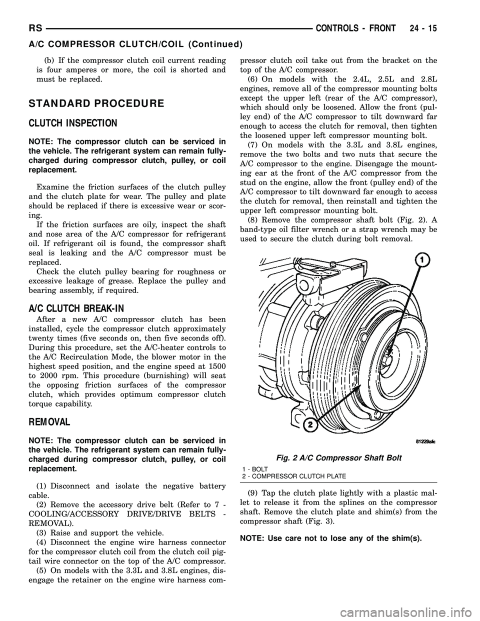
(8) Remove the compressor shaft bolt (Fig. 2). A
band-type oil filter wrench or a strap wrench may be
used to secure the clutch during bolt removal.
(9) Tap the clutch plate lightly with a plastic mal-
let to release it from the splines on the compressor
shaft. Remove the clutch plate and shim(s) from the
compressor shaft (Fig. 3).
NOTE: Use care not to lose any of the shim(s).
Fig. 2 A/C Compressor Shaft Bolt
1 - BOLT
2 - COMPRESSOR CLUTCH PLATE
RSCONTROLS - FRONT24-15
A/C COMPRESSOR CLUTCH/COIL (Continued)
Page 2168 of 2339
compressor. The bevel side of the snap ring must face
outward and both snap ring eyelets must be oriented
to the right or the left of the clutch coil dowel pin
location on the A/C compressor. Be certain that the
snap ring is fully and properly seated in the groove.
CAUTION: If the snap ring is not fully seated in the
groove it will vibrate out, resulting in a clutch fail-
ure and severe damage to the compressor front
cover.
(3) Install and securely tighten the screw that
secures the clutch coil pigtail wire connector bracket
and ground clip to the top of the compressor housing.
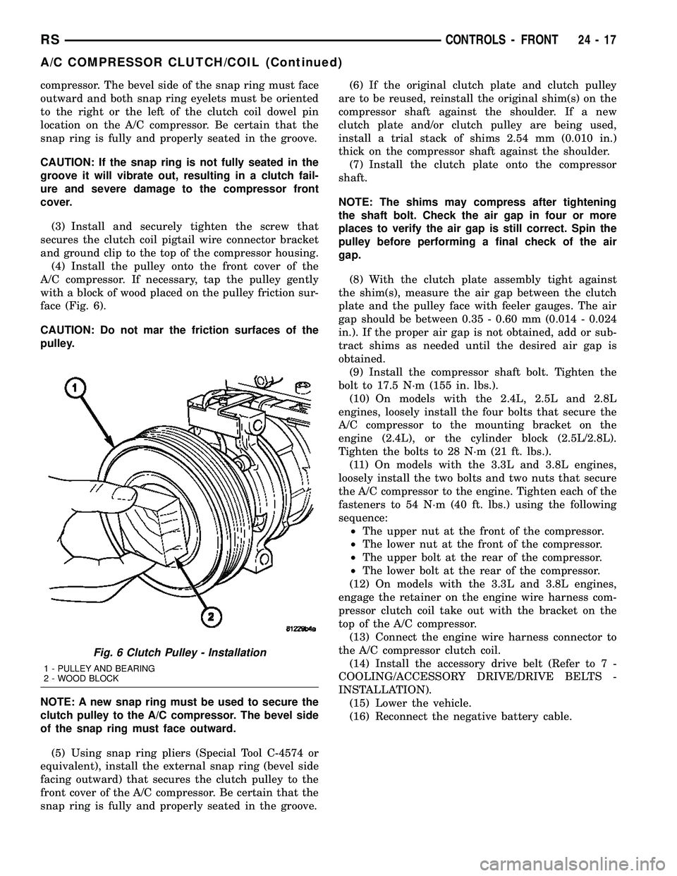
(4) Install the pulley onto the front cover of the
A/C compressor. If necessary, tap the pulley gently
with a block of wood placed on the pulley friction sur-
face (Fig. 6).
CAUTION: Do not mar the friction surfaces of the
pulley.
NOTE: A new snap ring must be used to secure the
clutch pulley to the A/C compressor. The bevel side
of the snap ring must face outward.
(5) Using snap ring pliers (Special Tool C-4574 or
equivalent), install the external snap ring (bevel side
facing outward) that secures the clutch pulley to the
front cover of the A/C compressor. Be certain that the
snap ring is fully and properly seated in the groove.(6) If the original clutch plate and clutch pulley
are to be reused, reinstall the original shim(s) on the
compressor shaft against the shoulder. If a new
clutch plate and/or clutch pulley are being used,
install a trial stack of shims 2.54 mm (0.010 in.)
thick on the compressor shaft against the shoulder.
(7) Install the clutch plate onto the compressor
shaft.
NOTE: The shims may compress after tightening
the shaft bolt. Check the air gap in four or more
places to verify the air gap is still correct. Spin the
pulley before performing a final check of the air
gap.
(8) With the clutch plate assembly tight against
the shim(s), measure the air gap between the clutch
plate and the pulley face with feeler gauges. The air
gap should be between 0.35 - 0.60 mm (0.014 - 0.024
in.). If the proper air gap is not obtained, add or sub-
tract shims as needed until the desired air gap is
obtained.
(9) Install the compressor shaft bolt. Tighten the
bolt to 17.5 N´m (155 in. lbs.).
(10) On models with the 2.4L, 2.5L and 2.8L
engines, loosely install the four bolts that secure the
A/C compressor to the mounting bracket on the
engine (2.4L), or the cylinder block (2.5L/2.8L).
Tighten the bolts to 28 N´m (21 ft. lbs.).
(11) On models with the 3.3L and 3.8L engines,
loosely install the two bolts and two nuts that secure
the A/C compressor to the engine. Tighten each of the
fasteners to 54 N´m (40 ft. lbs.) using the following
sequence:
²The upper nut at the front of the compressor.
²The lower nut at the front of the compressor.
²The upper bolt at the rear of the compressor.
²The lower bolt at the rear of the compressor.
(12) On models with the 3.3L and 3.8L engines,
engage the retainer on the engine wire harness com-
pressor clutch coil take out with the bracket on the
top of the A/C compressor.
(13) Connect the engine wire harness connector to
the A/C compressor clutch coil.
(14) Install the accessory drive belt (Refer to 7 -
COOLING/ACCESSORY DRIVE/DRIVE BELTS -
INSTALLATION).
(15) Lower the vehicle.
(16) Reconnect the negative battery cable.
Fig. 6 Clutch Pulley - Installation
1 - PULLEY AND BEARING
2 - WOOD BLOCK
RSCONTROLS - FRONT24-17
A/C COMPRESSOR CLUTCH/COIL (Continued)
Page 2194 of 2339
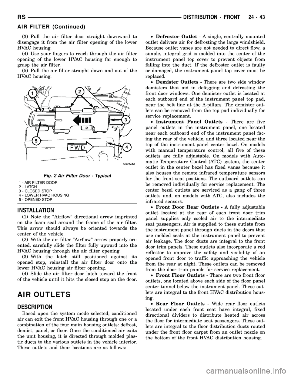
(3) Pull the air filter door straight downward to
disengage it from the air filter opening of the lower
HVAC housing.
(4) Use your fingers to reach through the air filter
opening of the lower HVAC housing far enough to
grasp the air filter.
(5) Pull the air filter straight down and out of the
HVAC housing.
INSTALLATION
(1) Note the ªAirflowº directional arrow imprinted
on the foam seal around the frame of the air filter.
This arrow should always be oriented towards the
center of the vehicle.
(2) With the air filter ªAirflowº arrow properly ori-
ented, carefully slide the filter fully upward into the
HVAC housing through the air filter opening.
(3) With the latch still positioned against its
opened stop, reinstall the air filter door onto the
lower HVAC housing air filter opening.
(4) Slide the air filter door latch toward the front
of the vehicle until it hits the closed stop on the door.
AIR OUTLETS
DESCRIPTION
Based upon the system mode selected, conditioned
air can exit the front HVAC housing through one or a
combination of the four main housing outlets: defrost,
demist, panel, or floor. Once the conditioned air exits
the unit housing, it is directed through molded plas-
tic ducts to the various outlets in the vehicle interior.
These outlets and their locations are as follows:²Defroster Outlet- A single, centrally mounted
outlet delivers air for defrosting the large windshield.
Because outlet vanes are not needed to direct flow, a
simple, integral grid is molded into the center of the
instrument panel top cover to prevent objects from
falling into the duct. If the defroster outlet is faulty
or damaged, the instrument panel top cover must be
replaced.
²Demister Outlets- There are two side window
demisters that aid in defogging and defrosting the
front door windows. One demister outlet is located at
each outboard end of the instrument panel top pad,
near the belt line at the A-pillars. The demister out-
lets can be removed from the top pad individually for
service replacement.
²Instrument Panel Outlets- There are five
panel outlets in the instrument panel, one located
near each outboard end of the instrument panel fac-
ing the rear of the vehicle, and three located near the
top of the instrument panel center bezel. On models
with manual temperature control, all five of these
outlets are fully adjustable. On models with Auto-
matic Temperature Control (ATC) system, the center
outlet in the center bezel has fixed vanes because it
also houses the remote infrared temperature sensors
for the front seat positions. The outboard outlets can
be removed individually for service replacement. The
center bezel outlets are serviced as a gang of three
outlets and, on models with ATC, also includes the
infrared sensors.
²Front Door Rear Outlets- A fully adjustable
outlet located at the rear of each front door trim
panel supplies only cooled air to the intermediate
seat passengers. Air is supplied to these outlets from
the instrument panel through ducts in the doors that
use molded seals at the instrument panel to prevent
air leakage. The door ducts are integral to the front
door trim panels. These outlets also incorporate a red
reflector to improve the safety and visibility of an
opened front door to traffic approaching the vehicle
from the rear at night. These outlets can be removed
from the door trim panels for service replacement.
²Front Floor Outlets- There are two front floor
outlets, one located above each side of the floor panel
center tunnel below the instrument panel. These out-
lets are integral to the front HVAC distribution hous-
ing.
²Rear Floor Outlets- Wide rear floor outlets
located under each front seat have integral, fixed
directional dividers to distribute heated air across
the floor for intermediate seat passengers. These out-
lets are integral to the floor distribution ducts routed
under the front floor carpet from an outlet nozzle on
the bottom of the front HVAC distribution housing.
Fig. 2 Air Filter Door - Typical
1 - AIR FILTER DOOR
2-LATCH
3 - CLOSED STOP
4 - LOWER HVAC HOUSING
5 - OPENED STOP
RSDISTRIBUTION - FRONT24-43
AIR FILTER (Continued)
Page 2223 of 2339
(4) Open both the suction and discharge valves,
then open the charge valve to allow the heated
refrigerant to flow into the system.
(5) When the transfer of refrigerant has stopped,
close both the suction and discharge valves.
(6) If all of the refrigerant charge did not transfer
from the dispensing device, open all of the windows
in the vehicle and set the heater-air conditioner con-
trols so that the compressor is engaged and the
blower motor is operating at its lowest speed setting.
Run the engine at a steady high idle (about 1400
rpm). If the compressor will not engage, test the com-
pressor clutch control circuit and repair as required.
(7) Open the suction valve to allow the remaining
refrigerant to transfer to the refrigerant system.
WARNING: TAKE CARE NOT TO OPEN THE DIS-
CHARGE (HIGH PRESSURE) VALVE AT THIS TIME.
(8) Close the suction valve and test the system
performance. (Refer to 24 - HEATING & AIR CON-
DITIONING - STANDARD PROCEDURE - A/C PER-
FORMANCE TEST).
(9) Disconnect the charging station and manifold
gauge set from the refrigerant system service ports.
(10) Reinstall the caps onto the refrigerant system
service ports.
(11) Run the HVAC Control Cooldown test to ver-
ify proper operation(Refer to 24 - HEATING & AIR
CONDITIONING - DIAGNOSIS AND TESTING).
A/C COMPRESSOR
DESCRIPTION
A/C COMPRESSOR
Vehicles equipped with the 2.4L gasoline, 2.5L die-
sel, 2.8L diesel and 3.3L gasoline engines with the
front heating-A/C system only, use the Denso 10S17
A/C compressor. Vehicles equipped with the 3.3L and
the 3.8L gasoline engines with the optional rear heat-
ing-A/C system use the Denso 10S20 A/C compressor.
Both A/C compressors include an integral high pres-
sure relief valve. The A/C compressor is secured to a
mounting bracket on the 2.4L gasoline engine and
directly to the cylinder block on the 2.5L diesel, 2.8L
diesel, 3.3L gasoline and 3.8L gasoline engines.
HIGH PRESSURE RELIEF VALVE
A high pressure relief valve is located on the rear
of the A/C compressor. This mechanical valve is
designed to vent refrigerant from the A/C system to
protect against damage to the compressor and other
system components, caused by condenser air flow
restriction or an overcharge of refrigerant.
OPERATION
A/C COMPRESSOR
The A/C compressor is driven by the engine
through an electric clutch, drive pulley and belt
arrangement. The compressor is lubricated by refrig-
erant oil that is circulated throughout the refrigerant
system with the refrigerant.
The compressor draws in low-pressure refrigerant
vapor from the evaporator through its suction port. It
then compresses the refrigerant into a high-pressure,
high-temperature refrigerant vapor. The compressor
pumps the high-pressure refrigerant vapor to the
condenser through the compressor discharge port.
The compressor cannot be repaired. If faulty or
damaged, the entire compressor assembly must be
replaced. The compressor clutch, pulley and clutch
coil are available for service.
HIGH PRESSURE RELIEF VALVE
The high pressure relief valve vents the system
when a discharge pressure of 3445 to 4135 kPa (500
to 600 psi) or above is reached. The valve closes
when a minimum discharge pressure of 2756 kPa
(400 psi) is reached.
The high pressure relief valve vents only enough
refrigerant to reduce the system pressure, and then
re-seats itself. The majority of the refrigerant is con-
served in the system. If the valve vents refrigerant, it
does not mean that the valve is faulty.
The high pressure relief valve is a factory-cali-
brated unit. The valve cannot be adjusted or
repaired, and must not be removed or otherwise dis-
turbed. The valve is only serviced as a part of the
compressor assembly.
DIAGNOSIS AND TESTING
A/C COMPRESSOR NOISE DIAGNOSIS
Excessive noise while the air conditioning compres-
sor is operating can be caused by loose compressor
mounts, a loose compressor clutch, or high operating
pressures in the refrigerant system. Verify compres-
sor drive belt condition, proper compressor mounting,
correct refrigerant charge level, and compressor head
pressure before compressor repair is performed.
With the close tolerances within the compressor, it
is possible to experience a temporary lockup. The
longer the compressor is inactive, the more likely the
condition is to occur. This condition is the result of
normal refrigerant migration within the refrigerant
system caused by ambient temperature changes. The
refrigerant migration may wash the refrigerant oil
out of the compressor.
24 - 72 PLUMBING - FRONTRS
PLUMBING - FRONT (Continued)
Page 2302 of 2339
INDEX
ABS FASTENER TORQUE,SPECIFICATIONS ...................... 5-91
ABSORBER - DESCRIPTION, SHOCK .......2-36
ABSORBER - INSTALLATION, SHOCK ......2-38
ABSORBER - OPERATION, SHOCK ........2-36
ABSORBER - REMOVAL, SHOCK ..........2-36
ABSORBER (UPPER BUSHING) - ASSEMBLY, SHOCK .................... 2-37
ABSORBER (UPPER BUSHING) - DISASSEMBLY, SHOCK .................2-37
A/C CLUTCH BREAK-IN, STANDARD PROCEDURE ........................ 24-15
A/C COMPRESSOR CLUTCH COIL, DIAGNOSIS AND TESTING .............24-14
A/C COMPRESSOR CLUTCH RELAY - DESCRIPTION ....................... 24-18
A/C COMPRESSOR CLUTCH RELAY - INSTALLATION ....................... 24-19
A/C COMPRESSOR CLUTCH RELAY - OPERATION ......................... 24-18
A/C COMPRESSOR CLUTCH RELAY - REMOVAL .......................... 24-19
A/C COMPRESSOR CLUTCH/COIL - DESCRIPTION ....................... 24-13
A/C COMPRESSOR CLUTCH/COIL - OPERATION ......................... 24-13
A/C COMPRESSOR, DESCRIPTION .......24-72
A/C COMPRESSOR, INSTALLATION .......24-74
A/C COMPRESSOR MOUNTING BRACKET, 2.4L ENGINE ...........24-74,24-75
A/C COMPRESSOR NOISE DIAGNOSIS, DIAGNOSIS AND TESTING .............24-72
A/C COMPRESSOR, OPERATION .........24-72
A/C COMPRESSOR, REMOVAL ..........24-73
A/C CONDENSER - DESCRIPTION ........24-75
A/C CONDENSER - OPERATION ..........24-75
A/C COOL DOWN TEST, DIAGNOSIS AND TESTING ............................ 24-6
A/C DISCHARGE LINE - INSTALLATION . . . 24-80
A/C DISCHARGE LINE - REMOVAL .......24-79
A/C EVAPORATOR - DESCRIPTION . . 24-80,24-98
A/C EVAPORATOR - INSTALLATION ......24-81
A/C EVAPORATOR - OPERATION ....24-80,24-98
A/C EVAPORATOR - REMOVAL ..........24-81
A/C EVAPORATOR, INSTALLATION - REAR ............................. 24-100
A/C EVAPORATOR LINE EXTENSION, INSTALLATION - REAR ...............24-100
A/C EVAPORATOR LINE EXTENSION, REMOVAL - REAR .................... 24-99
A/C EVAPORATOR, REMOVAL - REAR .....24-98
A/C EXPANSION VALVE - DESCRIPTION . . 24-100
A/C EXPANSION VALVE - OPERATION ....24-100
A/C EXPANSION VALVE, DIAGNOSIS AND TESTING - FRONT .................... 24-82
A/C EXPANSION VALVE, DIAGNOSIS AND TESTING - REAR .................... 24-101
A/C HEATER CONTROL - DESCRIPTION . . . 24-19
A/C PERFORMANCE TEST, DIAGNOSIS AND TESTING ........................ 24-7
A/C PRESSURE TRANSDUCER - DESCRIPTION ....................... 24-20
A/C PRESSURE TRANSDUCER - OPERATION ......................... 24-20
A/C PRESSURE TRANSDUCER, DIAGNOSIS AND TESTING .............24-21
A/C SYSTEM - CAUTION ...............24-66
A/C SYSTEM, SPECIFICATIONS ..........24-11
A/C SYSTEM, WARNING ...............24-66
ACCELERATOR PEDAL - INSTALLATION . . . 14-28
ACCELERATOR PEDAL - REMOVAL .......14-28
ACCESSORY DRIVE BELT - DIAGNOSIS AND TESTING .........................7-7
ACCESSORY DRIVE BELT TENSION, SPECIFICATIONS .......................7-5
ACCUMULATOR - DESCRIPTION . . . 21-218,21-73
ACCUMULATOR - OPERATION ....21-218,21-73
A/C-HEATER CONTROL - DESCRIPTION . . . 24-33
A/C-HEATER CONTROL - INSTALLATION . . . 24-34
A/C-HEATER CONTROL - OPERATION .....24-33
A/C-HEATER CONTROL - REMOVAL ......24-33
A/C-HEATER CONTROL CALIBRATION, STANDARD PROCEDURE ...............24-19
ACTUATOR - DESCRIPTION, BLEND DOOR ........................ 24-22,24-34
ACTUATOR - DESCRIPTION, ENGAGE ......8N-9
ACTUATOR - DESCRIPTION, LATCH ......8N-13 ACTUATOR - DESCRIPTION, MODE
DOOR ............................. 24-29
ACTUATOR - DESCRIPTION, RECIRCULATION DOOR ................24-31
ACTUATOR - INSTALLATION, BLEND DOOR ........................ 24-22,24-35
ACTUATOR - INSTALLATION, ENGAGE ....8N-10
ACTUATOR - INSTALLATION, INSIDE HANDLE ............................ 23-27
ACTUATOR - INSTALLATION, LATCH .....8N-14
ACTUATOR - INSTALLATION, MODE DOOR ............................. 24-30
ACTUATOR - INSTALLATION, RECIRCULATION DOOR ................24-32
ACTUATOR - OPERATION, BLEND DOOR . . 24-22, 24-35
ACTUATOR - OPERATION, ENGAGE .......8N-9
ACTUATOR - OPERATION, LATCH ........8N-13
ACTUATOR - OPERATION, MODE DOOR . . . 24-29
ACTUATOR - OPERATION, RECIRCULATION DOOR ................24-31
ACTUATOR - REAR - DESCRIPTION, MODE DOOR ........................ 24-39
ACTUATOR - REAR - INSTALLATION, MODE DOOR ........................ 24-40
ACTUATOR - REAR - OPERATION, MODE DOOR ............................. 24-39
ACTUATOR - REAR - REMOVAL, MODE DOOR ............................. 24-39
ACTUATOR - REMOVAL, BLEND DOOR . . . 24-22, 24-35
ACTUATOR - REMOVAL, ENGAGE ..........8N-9
ACTUATOR - REMOVAL, INSIDE HANDLE . . 23-27
ACTUATOR - REMOVAL, LATCH .........8N-13
ACTUATOR - REMOVAL, MODE DOOR ....24-29
ACTUATOR - REMOVAL, RECIRCULATION DOOR ............................. 24-32
ADAPTER - INSTALLATION, FRONT DISC BRAKE CALIPER ...................... 5-31
ADAPTER - INSTALLATION, OIL FILTER . . . 9-142
ADAPTER - REMOVAL, FRONT DISC BRAKE CALIPER ...................... 5-31
ADAPTER - REMOVAL, OIL FILTER .......9-142
ADAPTIVE MEMORIES, OPERATION - FUEL CORRECTION OR ................14-24
ADDING ADDITIONAL COOLANT - STANDARD PROCEDURE .................7-4
ADDITIONAL COOLANT - STANDARD PROCEDURE, ADDING ...................7-4
ADHESIVE ATTACHED - INSTALLATION, EXTERIOR NAME PLATES ..............23-51
ADHESIVE ATTACHED - REMOVAL, EXTERIOR NAME PLATES ..............23-51
ADHESIVE LOCATIONS - FOLD-IN-FLOOR ONLY - SPECIFICATIONS,
STRUCTURAL ...................... 23-228
ADHESIVE LOCATIONS - SPECIFICATIONS, STRUCTURAL ........23-218
ADJUSTABLE - INSTALLATION, PEDALS ....5-43
ADJUSTABLE - REMOVAL, PEDALS .......5-40
ADJUSTABLE PEDALS SWITCH - INSTALLATION ........................ 5-11
ADJUSTABLE PEDALS SWITCH - REMOVAL ........................... 5-11
ADJUSTE R-BOR C-PILLAR -
INSTALLATION, SEAT BELT HEIGHT ......8O-38
ADJUSTE R-BOR C-PILLAR -
REMOVAL, SEAT BELT HEIGHT ..........8O-38
ADJUSTER - DIAGNOSIS AND TESTING, DRUM BRAKE AUTOMATIC ..............5-14
ADJUSTER - INSTALLATION, FRONT SEAT TRACK MANUAL ...............23-126
ADJUSTER - INSTALLATION, FRONT SEAT TRACK POWER ................23-124
ADJUSTER - REMOVAL, FRONT SEAT TRACK MANUAL .................... 23-125
ADJUSTER - REMOVAL, FRONT SEAT TRACK POWER ..................... 23-124
ADJUSTER KNOB - INSTALLATION, SEAT BELT HEIGHT ....................... 8O-38
ADJUSTER KNOB - REMOVAL, SEAT BELT HEIGHT ....................... 8O-38
ADJUSTER NOISE DIAGNOSIS - DIAGNOSIS AND TESTING, HYDRAULIC
LASH ............................... 9-34
ADJUSTER TENSION RELEASE - STANDARD PROCEDURE, PARKING
BRAKE AUTOMATIC .................... 5-63ADJUSTER TENSION RESET -
STANDARD PROCEDURE, PARKING
BRAKE AUTOMATIC .................... 5-64
ADJUSTER/MANUAL - OCS - INSTALLATION, FRONT SEAT TRACK ....23-128
ADJUSTER/MANUAL - OCS - REMOVAL, FRONT SEAT TRACK .................23-126
ADJUSTER/POWER - OCS - INSTALLATION, FRONT SEAT TRACK ....23-125
ADJUSTER/POWER - OCS - REMOVAL, FRONT SEAT TRACK .................23-124
ADJUSTERS - INSTALLATION, HYDRAULIC LASH ..................... 9-35
ADJUSTERS - REMOVAL, HYDRAULIC LASH ............................... 9-35
AERATION - DIAGNOSIS AND TESTING, COOLING SYSTEM .....................7-4
AFTER AN AIRBAG DEPLOYMENT - STANDARD PROCEDURE, SERVICE .......8O-7
AIR CLEANER ELEMENT - INSTALLATION . 9-101, 9-24
AIR CLEANER ELEMENT - REMOVAL . 9-101,9-24
AIR CLEANER HOUSING - INSTALLATION . 9-102, 9-25
AIR CLEANER HOUSING - REMOVAL . 9-101,9-25
AIR CONDITIONER, DESCRIPTION - HEATER ............................. 24-1
AIR CONDITIONER, OPERATION - HEATER ............................. 24-4
AIR CONTROL MOTOR - DESCRIPTION, IDLE ............................... 14-33
AIR CONTROL MOTOR - INSTALLATION, IDLE ............................... 14-33
AIR CONTROL MOTOR - OPERATION, IDLE ............................... 14-33
AIR CONTROL MOTOR - REMOVAL, IDLE . . 14-33
AIR EXHAUSTER - DESCRIPTION, REAR QUARTER PANEL/FENDER ..............23-59
AIR EXHAUSTER - INSTALLATION, REAR QUARTER PANEL/FENDER ..............23-60
AIR EXHAUSTER - REMOVAL, REAR QUARTER PANEL/FENDER ..............23-59
AIR FILTER - DESCRIPTION ............24-42
AIR FILTER - INSTALLATION ............24-43
AIR FILTER - REMOVAL ...............24-42
AIR GAP, SPECIFICATIONS - WHEEL SPEED SENSOR ....................... 5-91
AIR INTAKE PIPE - INSTALLATION ......24-115
AIR INTAKE PIPE - REMOVAL ..........24-115
AIR OUTLETS - DESCRIPTION .....24-43,24-56
AIR OUTLETS - INSTALLATION ..........24-56
AIR OUTLETS - REMOVAL .............24-56
AIR PRESSURE TESTS - DIAGNOSIS AND TESTING, CLUTCH ...........21-153,21-8
AIR TEMPERATURE SENSOR - DESCRIPTION, INLET .................14-34
AIRBAG - DESCRIPTION, CURTAIN .......8O-12
AIRBAG - DESCRIPTION, DRIVER ........8O-16
AIRBAG - DESCRIPTION, KNEE BLOCKER . 8O-22
AIRBAG - DESCRIPTION, PASSENGER ....8O-30
AIRBAG - INSTALLATION, CURTAIN ......8O-16
AIRBAG - INSTALLATION, DRIVER .......8O-18
AIRBAG - INSTALLATION, KNEE BLOCKER .......................... 8O-23
AIRBAG - INSTALLATION, PASSENGER . . . 8O-32
AIRBAG - OPERATION, CURTAIN ........8O-13
AIRBAG - OPERATION, DRIVER .........8O-16
AIRBAG - OPERATION, KNEE BLOCKER . . . 8O-22
AIRBAG - OPERATION, PASSENGER ......8O-30
AIRBAG - REMOVAL, CURTAIN ..........8O-14
AIRBAG - REMOVAL, DRIVER ...........8O-17
AIRBAG - REMOVAL, KNEE BLOCKER ....8O-23
AIRBAG - REMOVAL, PASSENGER .......8O-30
AIRBAG DEPLOYMENT - STANDARD PROCEDURE, SERVICE AFTER AN ........8O-7
AIRBAG DISABLED INDICATOR - DESCRIPTION, PASSENGER ............8O-33
AIRBAG DISABLED INDICATOR - INSTALLATION, PASSENGER ...........8O-34
AIRBAG DISABLED INDICATOR - OPERATION, PASSENGER ..............8O-33
AIRBAG DISABLED INDICATOR - REMOVAL, PASSENGER ...............8O-34
AIRBAG SYSTEM - DIAGNOSIS AND TESTING ............................ 8O-6
AIRBAGS - STANDARD PROCEDURE, HANDLING .......................... 8O-6
RS INDEX1
Description Group-Page Description Group-Page Description Group-Page