2005 CHRYSLER CARAVAN cooling
[x] Cancel search: coolingPage 1743 of 2339
OPERATION
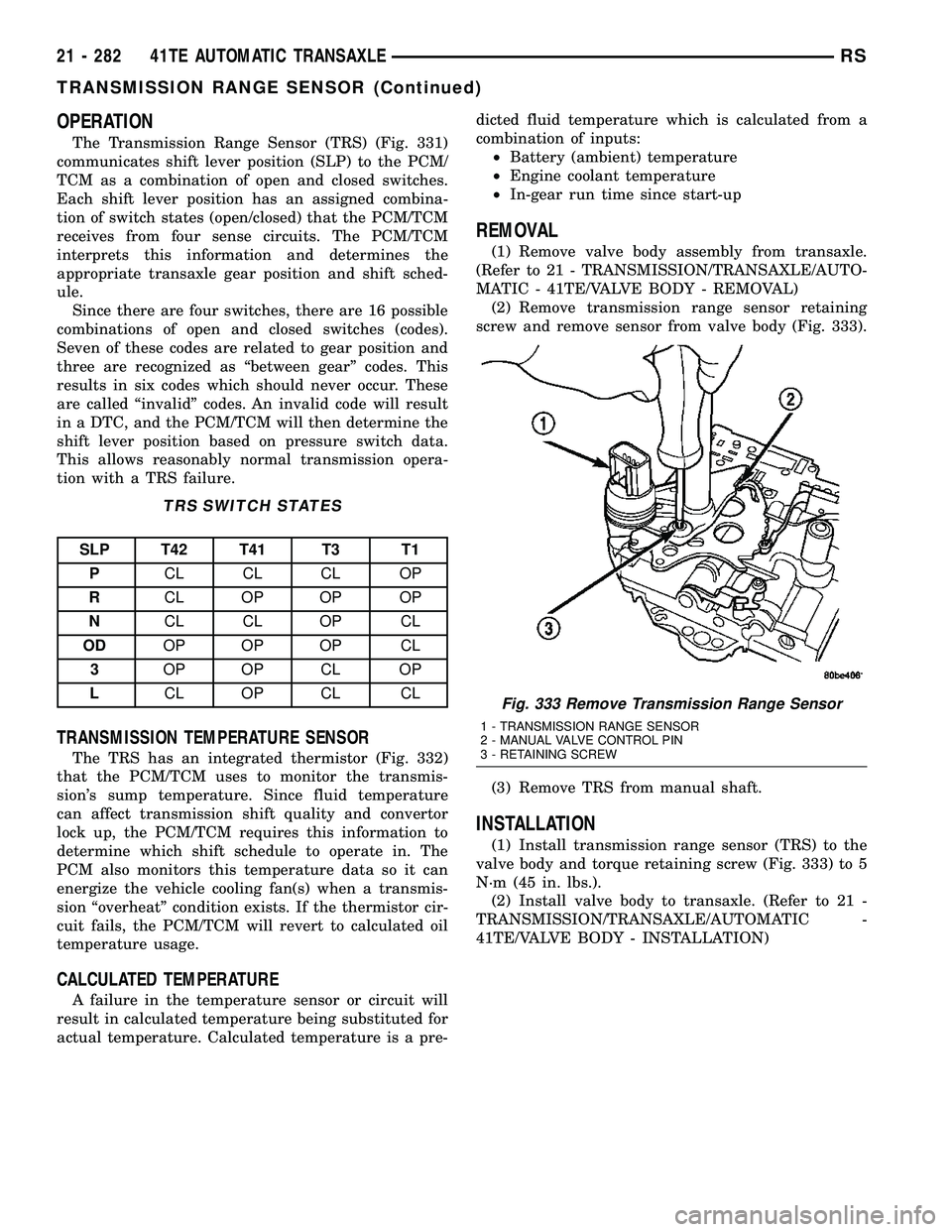
The Transmission Range Sensor (TRS) (Fig. 331)
communicates shift lever position (SLP) to the PCM/
TCM as a combination of open and closed switches.
Each shift lever position has an assigned combina-
tion of switch states (open/closed) that the PCM/TCM
receives from four sense circuits. The PCM/TCM
interprets this information and determines the
appropriate transaxle gear position and shift sched-
ule.
Since there are four switches, there are 16 possible
combinations of open and closed switches (codes).
Seven of these codes are related to gear position and
three are recognized as ªbetween gearº codes. This
results in six codes which should never occur. These
are called ªinvalidº codes. An invalid code will result
in a DTC, and the PCM/TCM will then determine the
shift lever position based on pressure switch data.
This allows reasonably normal transmission opera-
tion with a TRS failure.
TRS SWITCH STATES
SLP T42 T41 T3 T1
PCL CL CL OP
RCL OP OP OP
NCL CL OP CL
ODOP OP OP CL
3OP OP CL OP
LCL OP CL CL
TRANSMISSION TEMPERATURE SENSOR
The TRS has an integrated thermistor (Fig. 332)
that the PCM/TCM uses to monitor the transmis-
sion's sump temperature. Since fluid temperature
can affect transmission shift quality and convertor
lock up, the PCM/TCM requires this information to
determine which shift schedule to operate in. The
PCM also monitors this temperature data so it can
energize the vehicle cooling fan(s) when a transmis-
sion ªoverheatº condition exists. If the thermistor cir-
cuit fails, the PCM/TCM will revert to calculated oil
temperature usage.
CALCULATED TEMPERATURE
A failure in the temperature sensor or circuit will
result in calculated temperature being substituted for
actual temperature. Calculated temperature is a pre-dicted fluid temperature which is calculated from a
combination of inputs:
²Battery (ambient) temperature
²Engine coolant temperature
²In-gear run time since start-up
REMOVAL
(1) Remove valve body assembly from transaxle.
(Refer to 21 - TRANSMISSION/TRANSAXLE/AUTO-
MATIC - 41TE/VALVE BODY - REMOVAL)
(2) Remove transmission range sensor retaining
screw and remove sensor from valve body (Fig. 333).
(3) Remove TRS from manual shaft.
INSTALLATION
(1) Install transmission range sensor (TRS) to the
valve body and torque retaining screw (Fig. 333) to 5
N´m (45 in. lbs.).
(2) Install valve body to transaxle. (Refer to 21 -
TRANSMISSION/TRANSAXLE/AUTOMATIC -
41TE/VALVE BODY - INSTALLATION)
Fig. 333 Remove Transmission Range Sensor
1 - TRANSMISSION RANGE SENSOR
2 - MANUAL VALVE CONTROL PIN
3 - RETAINING SCREW
21 - 282 41TE AUTOMATIC TRANSAXLERS
TRANSMISSION RANGE SENSOR (Continued)
Page 2152 of 2339
HEATING & AIR CONDITIONING
TABLE OF CONTENTS
page page
HEATING & AIR CONDITIONING
DESCRIPTION
ENGINE COOLING SYSTEM
REQUIREMENTS.......................1
HEATER AND AIR CONDITIONER..........1
MANUAL SINGLE ZONE.................2
MANUAL DUAL ZONE...................2
MANUAL THREE ZONE..................2
AUTOMATIC TEMPERATURE CONTROL....3
OPERATION
HEATER AND AIR CONDITIONER..........4
MANUAL SINGLE ZONE.................4
MANUAL DUAL ZONE...................5
MANUAL THREE ZONE..................5AUTOMATIC TEMPERATURE CONTROL....5
DIAGNOSIS AND TESTING
A/C COOL DOWN TEST.................6
A/C PERFORMANCE TEST...............7
HEATER PERFORMANCE TEST..........10
SPECIFICATIONS
A/C SYSTEM.........................11
CONTROLS - FRONT.....................13
CONTROLS - REAR......................33
DISTRIBUTION - FRONT...................42
DISTRIBUTION - REAR....................56
PLUMBING - FRONT.....................64
PLUMBING - REAR......................98
CABIN HEATER........................113
HEATING & AIR
CONDITIONING
DESCRIPTION
ENGINE COOLING SYSTEM REQUIREMENTS
To maintain the performance level of the heating,
ventilation and air conditioning (HVAC) system, the
engine cooling system must be properly maintained.
The use of a bug screen is not recommended. Any
obstructions in front of the radiator or condenser will
reduce the performance of the air conditioning and
engine cooling systems.
The engine cooling system includes the radiator,
thermostat, radiator hoses and the engine coolant
pump. Refer to Cooling for more information before
opening or attempting any service to the engine cool-
ing system.
HEATER AND AIR CONDITIONER
A manually controlled single zone type heating-air
conditioning system, manually controlled dual zone
type heating-air conditioning system, manually con-
trolled three zone type heating-air conditioning sys-
tem or an automatic controlled three zone type
heating-air conditioning system is available on this
model.
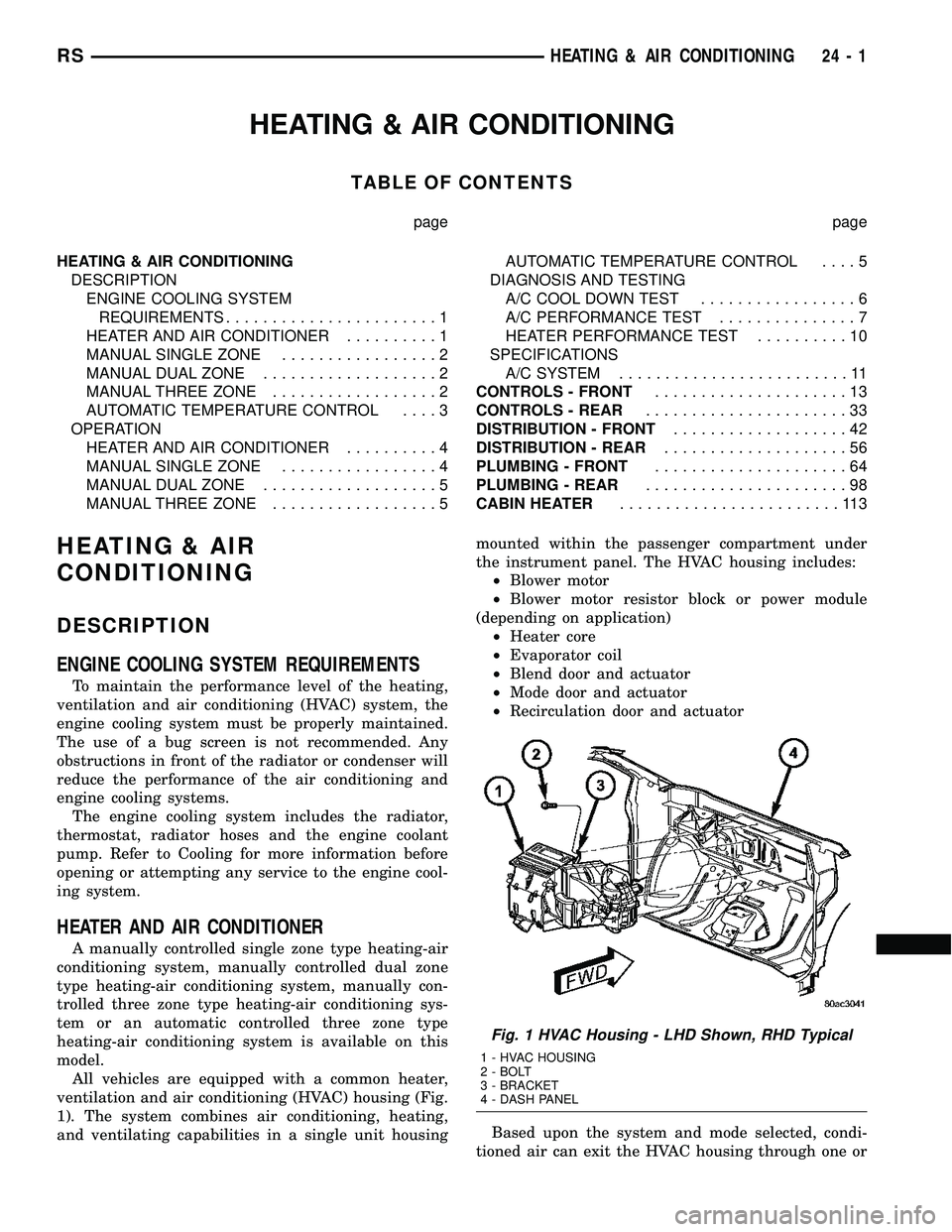
All vehicles are equipped with a common heater,
ventilation and air conditioning (HVAC) housing (Fig.
1). The system combines air conditioning, heating,
and ventilating capabilities in a single unit housingmounted within the passenger compartment under
the instrument panel. The HVAC housing includes:
²Blower motor
²Blower motor resistor block or power module
(depending on application)
²Heater core
²Evaporator coil
²Blend door and actuator
²Mode door and actuator
²Recirculation door and actuator
Based upon the system and mode selected, condi-
tioned air can exit the HVAC housing through one or
Fig. 1 HVAC Housing - LHD Shown, RHD Typical
1 - HVAC HOUSING
2 - BOLT
3 - BRACKET
4 - DASH PANEL
RSHEATING & AIR CONDITIONING24-1
Page 2155 of 2339
²a rotary knob for front fan speed selection can
override the automatic controls. LEDs surrounding
the knob show the current setting.
²a rotary knob for control of the rear system
(Three-Zone ATC system only).
²a rotary knob for mode control can override the
automatic controls. LEDs surrounding the knob show
the current setting.
²computer logic which remembers the settings of
the controls when the ignition is turned off and
retains those settings after a restart. If the system is
off when the ignition is turned off it will be off when
the engine is restarted, etc.
²computer logic which provides variable air recir-
culation under high temperature and humidity condi-
tions. Because recirculation is generally accompanied
by increased fan noise, the proportion of recirculated
to outside air gradually approaches full recirculation
over a broad temperature range.
²computer logic which enables additional heat for
diesel equipped vehicles by using a supplemental
engine coolant heater.
REAR CONTROL PANEL
The Three-Zone ATC sytem utilizes a rear control
panel centrally mounted on the headliner which
includes a VF digital display, a rocker control for
temperature and rotary controls for adjustment of
mode and fan speed of the rear heating-A/C system
by intermediate seat passengers.
OPERATION
HEATER AND AIR CONDITIONER
The heating and air conditioning systems pulls
outside (ambient) air through the cowl opening at the
base of the windshield and into the plenum chamber
above the heating, ventilation and air conditioning
(HVAC) housing, then through the evaporator coil.
Air flow can be directed either through or around the
heater core by adjusting the blend door with the tem-
perature control knob on the A/C-heater control
located on instrument panel. The air flow can then
be directed out from the panel, floor and defrost out-
lets in various combinations using the mode control
knob located on the A/C-heater control. Air flow
velocity can be adjusted with the blower speed selec-
tor located on the A/C-heater control.
NOTE: It is important to keep the air intake opening
clear of debris. Leaf particles and other debris that
is small enough to pass through the cowl opening
screen can accumulate within the HVAC housing.
The closed, warm, damp and dark environment cre-
ated within the housing is ideal for the growth of
certain molds, mildews and other fungi. Any accu-mulation of decaying plant matter provides an addi-
tional food source for fungal spores, which enter
the housing with the fresh intake-air. Excess debris,
as well as objectionable odors created by decaying
plant matter and growing fungi can be discharged
into the passenger compartment during heater-A/C
operation if the air intake opening is not kept clear
of debris.
The heater and air conditioning system is a blend-
air type system. In a blend-air system, a blend door
controls the amount of conditioned air that is allowed
to flow through, or around, the heater core. The tem-
perature control knob determines the discharge air
temperature by actuating an electric motor, which
operates the blend door. This allows an almost imme-
diate control of the output air temperature of the sys-
tem.
On all models, the outside air intake can be shut
off by pressing the Recirculation button on the A/C-
heater control. This will operate a electric actuated
recirculation air door that closes off the outside fresh
air intake and recirculates the air that is already
inside the vehicle.
The air conditioning compressor can be engaged in
any mode by pressing the snowflake, A/C on/off but-
ton. It can also be engaged by placing the mode con-
trol in the mix to defrost positions. This will remove
heat and humidity from the air before it is directed
through or around the heater core. The mode control
knob on the A/C-heater control is used to also direct
the conditioned air to the selected system outlets.
The mode control switch uses an electric motor to
control the mode doors.MANUAL SINGLE ZONE
²The temperature control knob enables continu-
ously variable proportioning of the conditioned air.
²The mode control knob enables continuously
variable proportioning of air flow between modes and
has detents adjacent to each icon.
²The blower control provides four separate speeds
and an Off position.
²When the heater-A/C system is off, the HVAC
computer closes the recirculation door to prevent out-
side air from entering the passenger compartment.
²Interior air may be recirculated to speed up
heating or cooling in all modes except defrost and
mix by pressing the Recirculate button on the A/C-
heater control.
²To reduce humidity for rapid defogging, the A/C
compressor runs automatically in modes from ªmixº
to full defrost when outside temperatures are above
freezing.
²Air conditioning is available in any mode by
pressing the snowflake, A/C on/off button.
24 - 4 HEATING & AIR CONDITIONINGRS
HEATING & AIR CONDITIONING (Continued)
Page 2156 of 2339
MANUAL DUAL ZONE
²The two slide controls enable continuously vari-
able proportioning of the conditioned air.
²The mode control knob enables continuously
variable proportioning of air flow between modes and
has detents adjacent to each icon.
²The blower control provides four separate speeds
and an Off position.
²When the heater-A/C system is off, the HVAC
computer closes the recirculation door to prevent out-
side air from entering the passenger compartment.
²Interior air may be recirculated to speed up
heating or cooling in all modes except defrost and
mix by pressing the Recirculate button on the A/C-
heater control.
²To reduce humidity for rapid defogging, the A/C
compressor runs automatically in modes from ªmixº
to full defrost when outside temperatures are above
freezing.
²Air conditioning is available in any mode by
pressing the snowflake, A/C on/off button.
MANUAL THREE ZONE
FRONT CONTROL PANEL
²Primary control of the rear heater-A/C system is
on the instrument panel. This control allows the
driver to set the rear compartment fan speed, to turn
the rear heater-A/C system off, or to give control to
the intermediate seat occupants by switching to the
Rear position. When the rear heater-A/C system is
controlled from the instrument panel, rear air tem-
perature is based on the driver-side temperature con-
trol position, and the mode (floor or overhead air) is
based on the front control's mode position.
²The mode control knob enables continuously
variable proportioning of air flow between modes but
has detents adjacent to each icon.
²The blower control provides four separate speeds
and an Off position. When the heater-A/C system is
off, the HVAC computer closes the recirculation door
to prevent outside air from entering the passenger
compartment.
²Interior air may be recirculated to speed up
heating or cooling in all modes except defrost and
mix by pressing the Recirculate button on the control
panel.
²To reduce humidity for rapid defogging the A/C
compressor runs automatically in modes from ªmix'
to full defrost when outside temperatures are above
freezing.
²Air conditioning is available in any mode by
pressing the snowflake, A/C on/off, button.
REAR CONTROL PANEL
With the rear control active, temperature selection
dictates the air distribution mode (floor or overhead
air) of the rear unit: a cool temperature setting
directs flow to the overhead outlets and a warm tem-
perature setting to the floor.
AUTOMATIC TEMPERATURE CONTROL
Comfort temperature or perceived temperature is
affected by air flow, sun levels on exposed skin, etc.
The air temperature may be higher or lower than the
comfort temperature. The automatic temperature
control (ATC) system uses two infrared sensors in the
instrument panel center stack to measure the tem-
perature of the front occupants in order determine
their comfort level relative to their selected comfort
temperature. The integral HVAC computer adjusts
temperature and air flow rates to maintain the cus-
tomer-perceived comfort temperatures. The air tem-
perature in the passenger compartment may be
slightly higher or lower than the comfort tempera-
ture at any time. For instance, on sunny summer
days the air flow will probably be cooler than the
comfort temperature; on cold or cloudy days and at
night it will probably be slightly warmer.
The Three-Zone ATC system uses the infrared sen-
sors located in the instrument panel center stack
along with an offset calibration strategy to meet the
comfort requirements of the rear seat occupants.
FRONT CONTROL PANEL
²AUTO HI/LO± This system features two sets of
automatic control logic that allow either a rapid cool-
down rate or a somewhat slower cool-down rate with
less fan noise. HI-AUTO controls the system to reach
its assigned temperature quickly with a higher fan
speed. LO-AUTO controls the system to reach its
assigned temperature somewhat slower with less fan
noise. Both modes will automatically engage auto
recirculation.
²DEFROST± The defrost function must be man-
ually selected to direct air flow to the windshield to
remove fog or ice. The ATC system cannot automati-
cally sense the presence of fog or ice on the wind-
shield.
²RECIRC± The RECIRC button will close the
air inlet door. If the system is in auto recirc (indica-
tor being displayed automatically), pressing the man-
ual recirc button will disable the auto recirc function
until one of the auto keys are pressed or the ignition
is cycled. If Auto HI/LO is pressed while manual
recirc is active, manual recirc will be deactivated.
²REAR WINDOW DEFOGGER± Pushing the
button sends a PCI bus message to the intelligent
power module which controls the rear window defog-
ger and side view mirror (if equipped) circuitry. The
RSHEATING & AIR CONDITIONING24-5
HEATING & AIR CONDITIONING (Continued)
Page 2160 of 2339
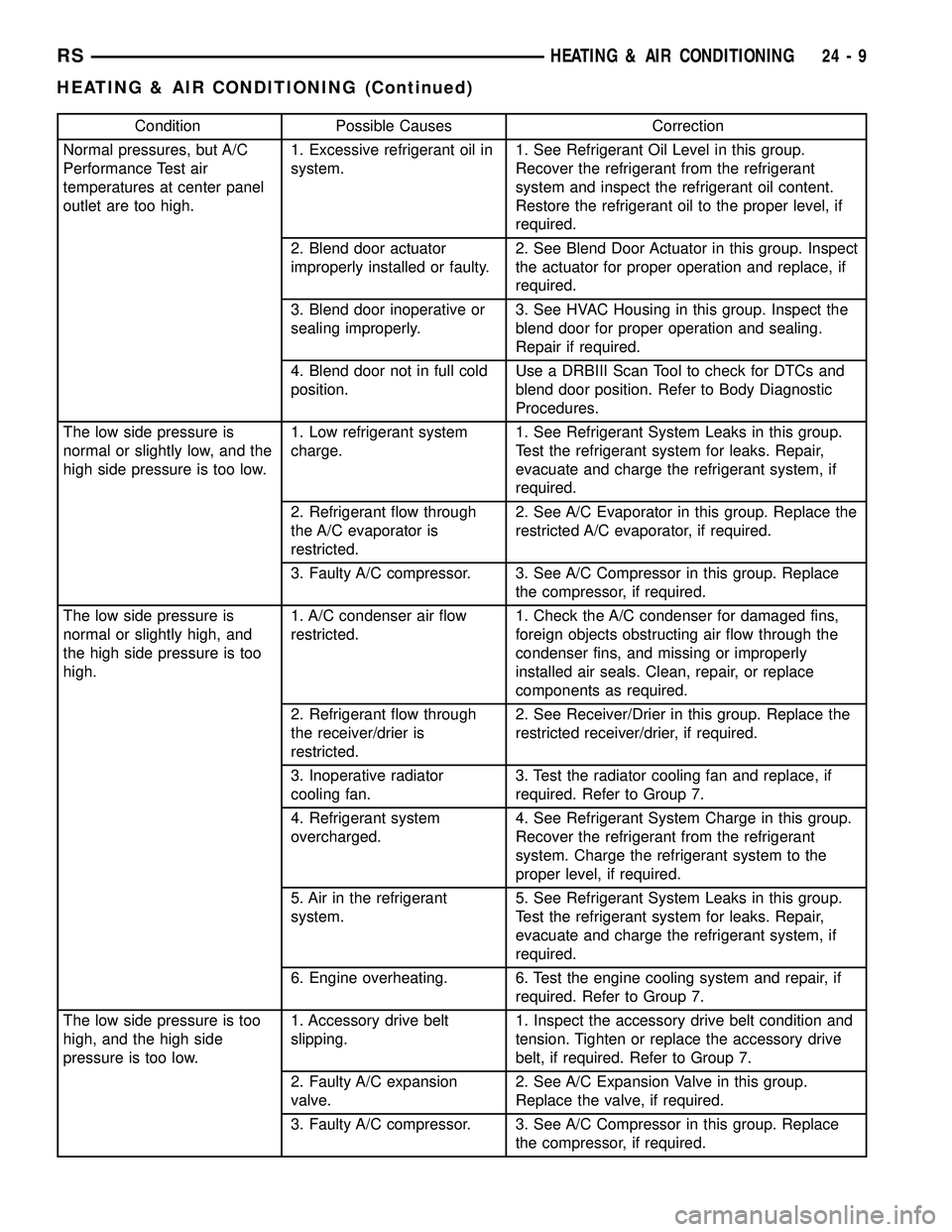
Condition Possible Causes Correction
Normal pressures, but A/C
Performance Test air
temperatures at center panel
outlet are too high.1. Excessive refrigerant oil in
system.1. See Refrigerant Oil Level in this group.
Recover the refrigerant from the refrigerant
system and inspect the refrigerant oil content.
Restore the refrigerant oil to the proper level, if
required.
2. Blend door actuator
improperly installed or faulty.2. See Blend Door Actuator in this group. Inspect
the actuator for proper operation and replace, if
required.
3. Blend door inoperative or
sealing improperly.3. See HVAC Housing in this group. Inspect the
blend door for proper operation and sealing.
Repair if required.
4. Blend door not in full cold
position.Use a DRBIII Scan Tool to check for DTCs and
blend door position. Refer to Body Diagnostic
Procedures.
The low side pressure is
normal or slightly low, and the
high side pressure is too low.1. Low refrigerant system
charge.1. See Refrigerant System Leaks in this group.
Test the refrigerant system for leaks. Repair,
evacuate and charge the refrigerant system, if
required.
2. Refrigerant flow through
the A/C evaporator is
restricted.2. See A/C Evaporator in this group. Replace the
restricted A/C evaporator, if required.
3. Faulty A/C compressor. 3. See A/C Compressor in this group. Replace
the compressor, if required.
The low side pressure is
normal or slightly high, and
the high side pressure is too
high.1. A/C condenser air flow
restricted.1. Check the A/C condenser for damaged fins,
foreign objects obstructing air flow through the
condenser fins, and missing or improperly
installed air seals. Clean, repair, or replace
components as required.
2. Refrigerant flow through
the receiver/drier is
restricted.2. See Receiver/Drier in this group. Replace the
restricted receiver/drier, if required.
3. Inoperative radiator
cooling fan.3. Test the radiator cooling fan and replace, if
required. Refer to Group 7.
4. Refrigerant system
overcharged.4. See Refrigerant System Charge in this group.
Recover the refrigerant from the refrigerant
system. Charge the refrigerant system to the
proper level, if required.
5. Air in the refrigerant
system.5. See Refrigerant System Leaks in this group.
Test the refrigerant system for leaks. Repair,
evacuate and charge the refrigerant system, if
required.
6. Engine overheating. 6. Test the engine cooling system and repair, if
required. Refer to Group 7.
The low side pressure is too
high, and the high side
pressure is too low.1. Accessory drive belt
slipping.1. Inspect the accessory drive belt condition and
tension. Tighten or replace the accessory drive
belt, if required. Refer to Group 7.
2. Faulty A/C expansion
valve.2. See A/C Expansion Valve in this group.
Replace the valve, if required.
3. Faulty A/C compressor. 3. See A/C Compressor in this group. Replace
the compressor, if required.
RSHEATING & AIR CONDITIONING24-9
HEATING & AIR CONDITIONING (Continued)
Page 2161 of 2339
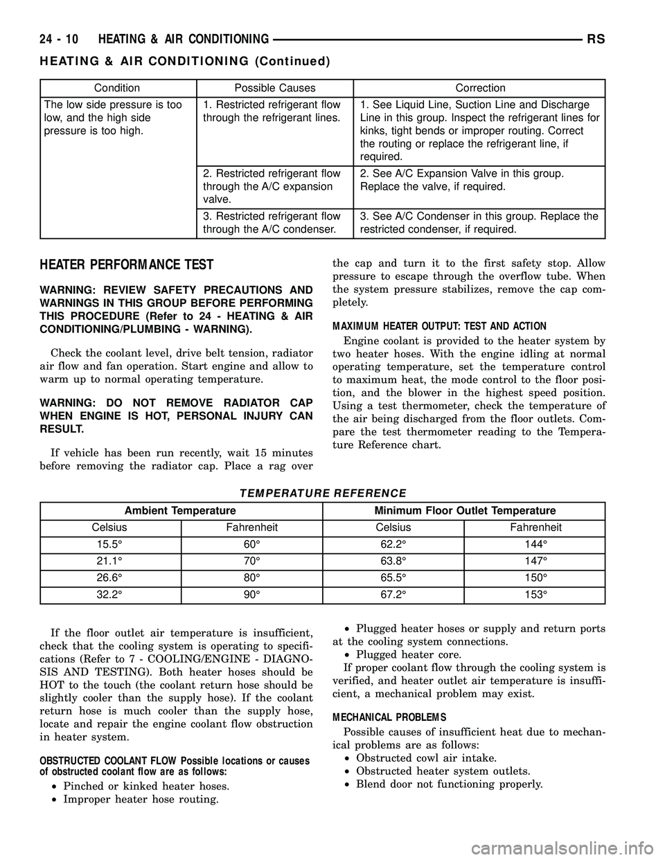
Condition Possible Causes Correction
The low side pressure is too
low, and the high side
pressure is too high.1. Restricted refrigerant flow
through the refrigerant lines.1. See Liquid Line, Suction Line and Discharge
Line in this group. Inspect the refrigerant lines for
kinks, tight bends or improper routing. Correct
the routing or replace the refrigerant line, if
required.
2. Restricted refrigerant flow
through the A/C expansion
valve.2. See A/C Expansion Valve in this group.
Replace the valve, if required.
3. Restricted refrigerant flow
through the A/C condenser.3. See A/C Condenser in this group. Replace the
restricted condenser, if required.
HEATER PERFORMANCE TEST
WARNING: REVIEW SAFETY PRECAUTIONS AND
WARNINGS IN THIS GROUP BEFORE PERFORMING
THIS PROCEDURE (Refer to 24 - HEATING & AIR
CONDITIONING/PLUMBING - WARNING).
Check the coolant level, drive belt tension, radiator
air flow and fan operation. Start engine and allow to
warm up to normal operating temperature.
WARNING: DO NOT REMOVE RADIATOR CAP
WHEN ENGINE IS HOT, PERSONAL INJURY CAN
RESULT.
If vehicle has been run recently, wait 15 minutes
before removing the radiator cap. Place a rag overthe cap and turn it to the first safety stop. Allow
pressure to escape through the overflow tube. When
the system pressure stabilizes, remove the cap com-
pletely.
MAXIMUM HEATER OUTPUT: TEST AND ACTION
Engine coolant is provided to the heater system by
two heater hoses. With the engine idling at normal
operating temperature, set the temperature control
to maximum heat, the mode control to the floor posi-
tion, and the blower in the highest speed position.
Using a test thermometer, check the temperature of
the air being discharged from the floor outlets. Com-
pare the test thermometer reading to the Tempera-
ture Reference chart.
TEMPERATURE REFERENCE
Ambient Temperature Minimum Floor Outlet Temperature
Celsius Fahrenheit Celsius Fahrenheit
15.5É 60É 62.2É 144É
21.1É 70É 63.8É 147É
26.6É 80É 65.5É 150É
32.2É 90É 67.2É 153É
If the floor outlet air temperature is insufficient,
check that the cooling system is operating to specifi-
cations (Refer to 7 - COOLING/ENGINE - DIAGNO-
SIS AND TESTING). Both heater hoses should be
HOT to the touch (the coolant return hose should be
slightly cooler than the supply hose). If the coolant
return hose is much cooler than the supply hose,
locate and repair the engine coolant flow obstruction
in heater system.
OBSTRUCTED COOLANT FLOW Possible locations or causes
of obstructed coolant flow are as follows:
²Pinched or kinked heater hoses.
²Improper heater hose routing.²Plugged heater hoses or supply and return ports
at the cooling system connections.
²Plugged heater core.
If proper coolant flow through the cooling system is
verified, and heater outlet air temperature is insuffi-
cient, a mechanical problem may exist.
MECHANICAL PROBLEMS
Possible causes of insufficient heat due to mechan-
ical problems are as follows:
²Obstructed cowl air intake.
²Obstructed heater system outlets.
²Blend door not functioning properly.
24 - 10 HEATING & AIR CONDITIONINGRS
HEATING & AIR CONDITIONING (Continued)
Page 2166 of 2339
(b) If the compressor clutch coil current reading
is four amperes or more, the coil is shorted and
must be replaced.
STANDARD PROCEDURE
CLUTCH INSPECTION
NOTE: The compressor clutch can be serviced in
the vehicle. The refrigerant system can remain fully-
charged during compressor clutch, pulley, or coil
replacement.
Examine the friction surfaces of the clutch pulley
and the clutch plate for wear. The pulley and plate
should be replaced if there is excessive wear or scor-
ing.
If the friction surfaces are oily, inspect the shaft
and nose area of the A/C compressor for refrigerant
oil. If refrigerant oil is found, the compressor shaft
seal is leaking and the A/C compressor must be
replaced.
Check the clutch pulley bearing for roughness or
excessive leakage of grease. Replace the pulley and
bearing assembly, if required.
A/C CLUTCH BREAK-IN
After a new A/C compressor clutch has been
installed, cycle the compressor clutch approximately
twenty times (five seconds on, then five seconds off).
During this procedure, set the A/C-heater controls to
the A/C Recirculation Mode, the blower motor in the
highest speed position, and the engine speed at 1500
to 2000 rpm. This procedure (burnishing) will seat
the opposing friction surfaces of the compressor
clutch, which provides optimum compressor clutch
torque capability.
REMOVAL
NOTE: The compressor clutch can be serviced in
the vehicle. The refrigerant system can remain fully-
charged during compressor clutch, pulley, or coil
replacement.
(1) Disconnect and isolate the negative battery
cable.
(2) Remove the accessory drive belt (Refer to 7 -
COOLING/ACCESSORY DRIVE/DRIVE BELTS -
REMOVAL).
(3) Raise and support the vehicle.
(4) Disconnect the engine wire harness connector
for the compressor clutch coil from the clutch coil pig-
tail wire connector on the top of the A/C compressor.
(5) On models with the 3.3L and 3.8L engines, dis-
engage the retainer on the engine wire harness com-pressor clutch coil take out from the bracket on the
top of the A/C compressor.
(6) On models with the 2.4L, 2.5L and 2.8L
engines, remove all of the compressor mounting bolts
except the upper left (rear of the A/C compressor),
which should only be loosened. Allow the front (pul-
ley end) of the A/C compressor to tilt downward far
enough to access the clutch for removal, then tighten
the loosened upper left compressor mounting bolt.
(7) On models with the 3.3L and 3.8L engines,
remove the two bolts and two nuts that secure the
A/C compressor to the engine. Disengage the mount-
ing ear at the front of the A/C compressor from the
stud on the engine, allow the front (pulley end) of the
A/C compressor to tilt downward far enough to access
the clutch for removal, then reinstall and tighten the
upper left compressor mounting bolt.
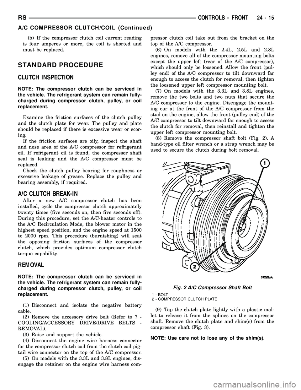
(8) Remove the compressor shaft bolt (Fig. 2). A
band-type oil filter wrench or a strap wrench may be
used to secure the clutch during bolt removal.
(9) Tap the clutch plate lightly with a plastic mal-
let to release it from the splines on the compressor
shaft. Remove the clutch plate and shim(s) from the
compressor shaft (Fig. 3).
NOTE: Use care not to lose any of the shim(s).
Fig. 2 A/C Compressor Shaft Bolt
1 - BOLT
2 - COMPRESSOR CLUTCH PLATE
RSCONTROLS - FRONT24-15
A/C COMPRESSOR CLUTCH/COIL (Continued)
Page 2168 of 2339
compressor. The bevel side of the snap ring must face
outward and both snap ring eyelets must be oriented
to the right or the left of the clutch coil dowel pin
location on the A/C compressor. Be certain that the
snap ring is fully and properly seated in the groove.
CAUTION: If the snap ring is not fully seated in the
groove it will vibrate out, resulting in a clutch fail-
ure and severe damage to the compressor front
cover.
(3) Install and securely tighten the screw that
secures the clutch coil pigtail wire connector bracket
and ground clip to the top of the compressor housing.
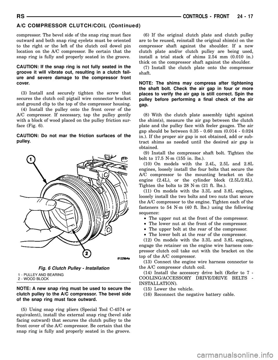
(4) Install the pulley onto the front cover of the
A/C compressor. If necessary, tap the pulley gently
with a block of wood placed on the pulley friction sur-
face (Fig. 6).
CAUTION: Do not mar the friction surfaces of the
pulley.
NOTE: A new snap ring must be used to secure the
clutch pulley to the A/C compressor. The bevel side
of the snap ring must face outward.
(5) Using snap ring pliers (Special Tool C-4574 or
equivalent), install the external snap ring (bevel side
facing outward) that secures the clutch pulley to the
front cover of the A/C compressor. Be certain that the
snap ring is fully and properly seated in the groove.(6) If the original clutch plate and clutch pulley
are to be reused, reinstall the original shim(s) on the
compressor shaft against the shoulder. If a new
clutch plate and/or clutch pulley are being used,
install a trial stack of shims 2.54 mm (0.010 in.)
thick on the compressor shaft against the shoulder.
(7) Install the clutch plate onto the compressor
shaft.
NOTE: The shims may compress after tightening
the shaft bolt. Check the air gap in four or more
places to verify the air gap is still correct. Spin the
pulley before performing a final check of the air
gap.
(8) With the clutch plate assembly tight against
the shim(s), measure the air gap between the clutch
plate and the pulley face with feeler gauges. The air
gap should be between 0.35 - 0.60 mm (0.014 - 0.024
in.). If the proper air gap is not obtained, add or sub-
tract shims as needed until the desired air gap is
obtained.
(9) Install the compressor shaft bolt. Tighten the
bolt to 17.5 N´m (155 in. lbs.).
(10) On models with the 2.4L, 2.5L and 2.8L
engines, loosely install the four bolts that secure the
A/C compressor to the mounting bracket on the
engine (2.4L), or the cylinder block (2.5L/2.8L).
Tighten the bolts to 28 N´m (21 ft. lbs.).
(11) On models with the 3.3L and 3.8L engines,
loosely install the two bolts and two nuts that secure
the A/C compressor to the engine. Tighten each of the
fasteners to 54 N´m (40 ft. lbs.) using the following
sequence:
²The upper nut at the front of the compressor.
²The lower nut at the front of the compressor.
²The upper bolt at the rear of the compressor.
²The lower bolt at the rear of the compressor.
(12) On models with the 3.3L and 3.8L engines,
engage the retainer on the engine wire harness com-
pressor clutch coil take out with the bracket on the
top of the A/C compressor.
(13) Connect the engine wire harness connector to
the A/C compressor clutch coil.
(14) Install the accessory drive belt (Refer to 7 -
COOLING/ACCESSORY DRIVE/DRIVE BELTS -
INSTALLATION).
(15) Lower the vehicle.
(16) Reconnect the negative battery cable.
Fig. 6 Clutch Pulley - Installation
1 - PULLEY AND BEARING
2 - WOOD BLOCK
RSCONTROLS - FRONT24-17
A/C COMPRESSOR CLUTCH/COIL (Continued)