2005 CHRYSLER CARAVAN radiator
[x] Cancel search: radiatorPage 1842 of 2339
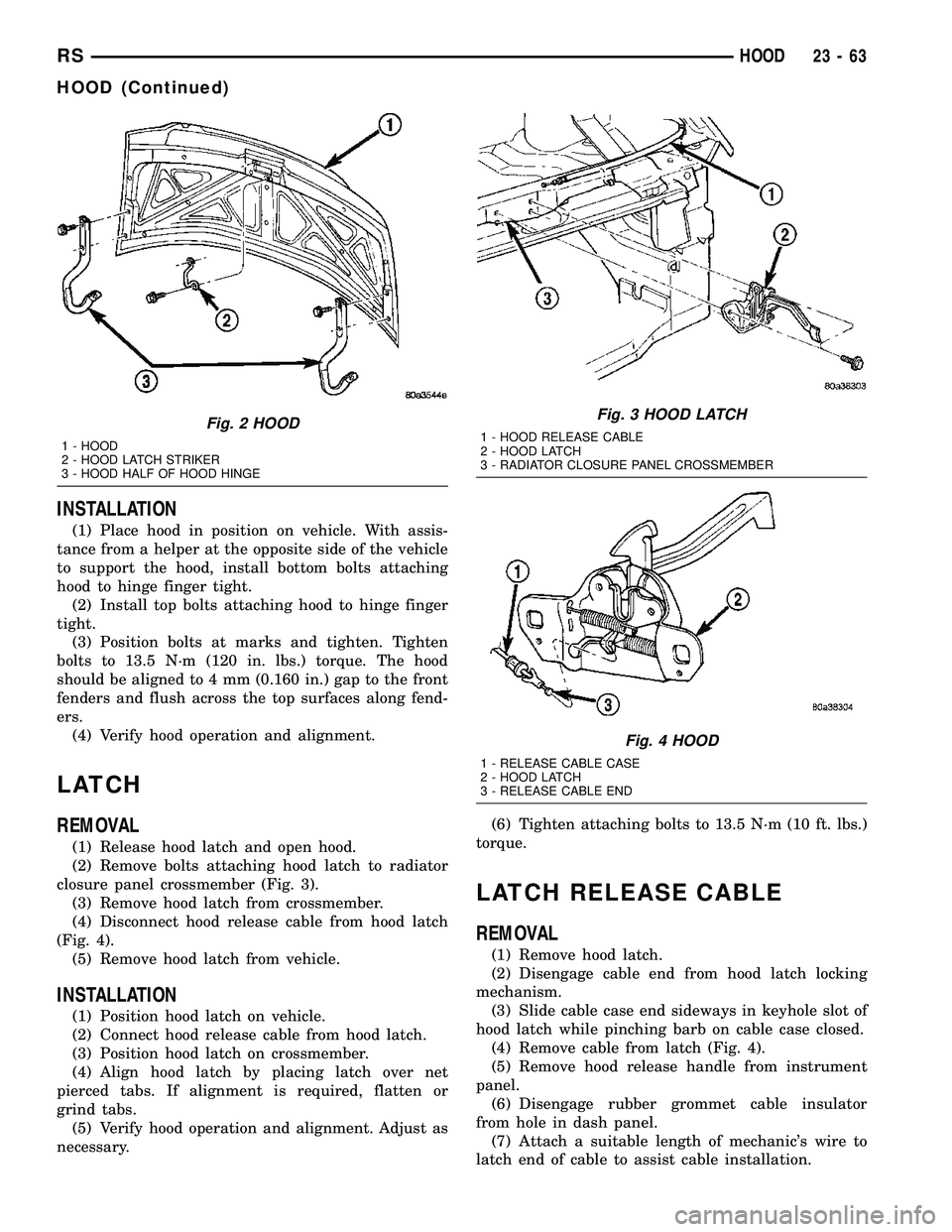
INSTALLATION
(1) Place hood in position on vehicle. With assis-
tance from a helper at the opposite side of the vehicle
to support the hood, install bottom bolts attaching
hood to hinge finger tight.
(2) Install top bolts attaching hood to hinge finger
tight.
(3) Position bolts at marks and tighten. Tighten
bolts to 13.5 N´m (120 in. lbs.) torque. The hood
should be aligned to 4 mm (0.160 in.) gap to the front
fenders and flush across the top surfaces along fend-
ers.
(4) Verify hood operation and alignment.
LATCH
REMOVAL
(1) Release hood latch and open hood.
(2) Remove bolts attaching hood latch to radiator
closure panel crossmember (Fig. 3).
(3) Remove hood latch from crossmember.
(4) Disconnect hood release cable from hood latch
(Fig. 4).
(5) Remove hood latch from vehicle.
INSTALLATION
(1) Position hood latch on vehicle.
(2) Connect hood release cable from hood latch.
(3) Position hood latch on crossmember.
(4) Align hood latch by placing latch over net
pierced tabs. If alignment is required, flatten or
grind tabs.
(5) Verify hood operation and alignment. Adjust as
necessary.(6) Tighten attaching bolts to 13.5 N´m (10 ft. lbs.)
torque.
LATCH RELEASE CABLE
REMOVAL
(1) Remove hood latch.
(2) Disengage cable end from hood latch locking
mechanism.
(3) Slide cable case end sideways in keyhole slot of
hood latch while pinching barb on cable case closed.
(4) Remove cable from latch (Fig. 4).
(5) Remove hood release handle from instrument
panel.
(6) Disengage rubber grommet cable insulator
from hole in dash panel.
(7) Attach a suitable length of mechanic's wire to
latch end of cable to assist cable installation.
Fig. 2 HOOD
1 - HOOD
2 - HOOD LATCH STRIKER
3 - HOOD HALF OF HOOD HINGE
Fig. 3 HOOD LATCH
1 - HOOD RELEASE CABLE
2 - HOOD LATCH
3 - RADIATOR CLOSURE PANEL CROSSMEMBER
Fig. 4 HOOD
1 - RELEASE CABLE CASE
2 - HOOD LATCH
3 - RELEASE CABLE END
RSHOOD23-63
HOOD (Continued)
Page 1843 of 2339
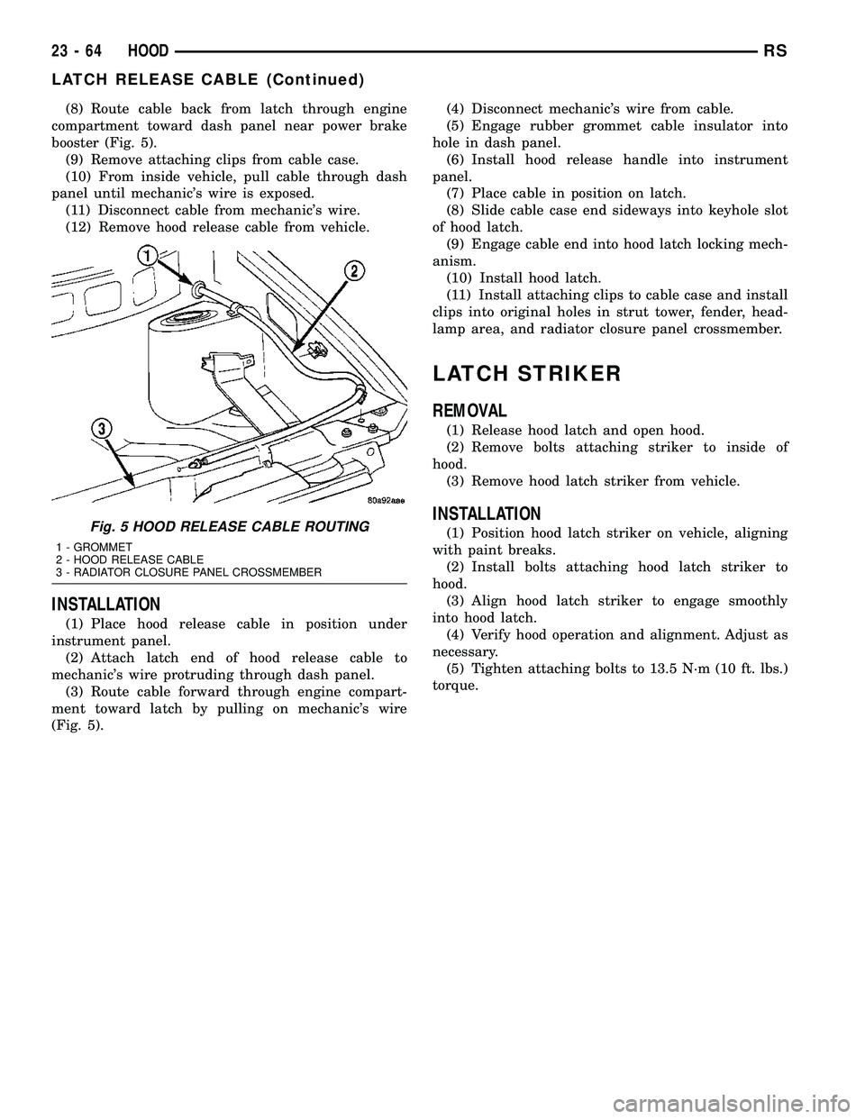
(8) Route cable back from latch through engine
compartment toward dash panel near power brake
booster (Fig. 5).
(9) Remove attaching clips from cable case.
(10) From inside vehicle, pull cable through dash
panel until mechanic's wire is exposed.
(11) Disconnect cable from mechanic's wire.
(12) Remove hood release cable from vehicle.
INSTALLATION
(1) Place hood release cable in position under
instrument panel.
(2) Attach latch end of hood release cable to
mechanic's wire protruding through dash panel.
(3) Route cable forward through engine compart-
ment toward latch by pulling on mechanic's wire
(Fig. 5).(4) Disconnect mechanic's wire from cable.
(5) Engage rubber grommet cable insulator into
hole in dash panel.
(6) Install hood release handle into instrument
panel.
(7) Place cable in position on latch.
(8) Slide cable case end sideways into keyhole slot
of hood latch.
(9) Engage cable end into hood latch locking mech-
anism.
(10) Install hood latch.
(11) Install attaching clips to cable case and install
clips into original holes in strut tower, fender, head-
lamp area, and radiator closure panel crossmember.
LATCH STRIKER
REMOVAL
(1) Release hood latch and open hood.
(2) Remove bolts attaching striker to inside of
hood.
(3) Remove hood latch striker from vehicle.
INSTALLATION
(1) Position hood latch striker on vehicle, aligning
with paint breaks.
(2) Install bolts attaching hood latch striker to
hood.
(3) Align hood latch striker to engage smoothly
into hood latch.
(4) Verify hood operation and alignment. Adjust as
necessary.
(5) Tighten attaching bolts to 13.5 N´m (10 ft. lbs.)
torque.Fig. 5 HOOD RELEASE CABLE ROUTING
1 - GROMMET
2 - HOOD RELEASE CABLE
3 - RADIATOR CLOSURE PANEL CROSSMEMBER
23 - 64 HOODRS
LATCH RELEASE CABLE (Continued)
Page 2013 of 2339
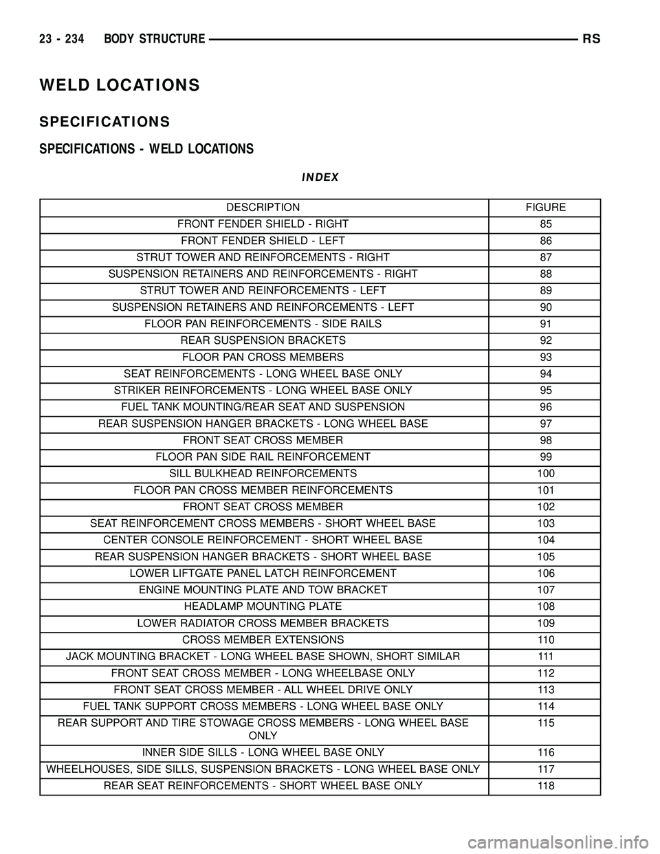
WELD LOCATIONS
SPECIFICATIONS
SPECIFICATIONS - WELD LOCATIONS
INDEX
DESCRIPTION FIGURE
FRONT FENDER SHIELD - RIGHT 85
FRONT FENDER SHIELD - LEFT 86
STRUT TOWER AND REINFORCEMENTS - RIGHT 87
SUSPENSION RETAINERS AND REINFORCEMENTS - RIGHT 88
STRUT TOWER AND REINFORCEMENTS - LEFT 89
SUSPENSION RETAINERS AND REINFORCEMENTS - LEFT 90
FLOOR PAN REINFORCEMENTS - SIDE RAILS 91
REAR SUSPENSION BRACKETS 92
FLOOR PAN CROSS MEMBERS 93
SEAT REINFORCEMENTS - LONG WHEEL BASE ONLY 94
STRIKER REINFORCEMENTS - LONG WHEEL BASE ONLY 95
FUEL TANK MOUNTING/REAR SEAT AND SUSPENSION 96
REAR SUSPENSION HANGER BRACKETS - LONG WHEEL BASE 97
FRONT SEAT CROSS MEMBER 98
FLOOR PAN SIDE RAIL REINFORCEMENT 99
SILL BULKHEAD REINFORCEMENTS 100
FLOOR PAN CROSS MEMBER REINFORCEMENTS 101
FRONT SEAT CROSS MEMBER 102
SEAT REINFORCEMENT CROSS MEMBERS - SHORT WHEEL BASE 103
CENTER CONSOLE REINFORCEMENT - SHORT WHEEL BASE 104
REAR SUSPENSION HANGER BRACKETS - SHORT WHEEL BASE 105
LOWER LIFTGATE PANEL LATCH REINFORCEMENT 106
ENGINE MOUNTING PLATE AND TOW BRACKET 107
HEADLAMP MOUNTING PLATE 108
LOWER RADIATOR CROSS MEMBER BRACKETS 109
CROSS MEMBER EXTENSIONS 110
JACK MOUNTING BRACKET - LONG WHEEL BASE SHOWN, SHORT SIMILAR 111
FRONT SEAT CROSS MEMBER - LONG WHEELBASE ONLY 112
FRONT SEAT CROSS MEMBER - ALL WHEEL DRIVE ONLY 113
FUEL TANK SUPPORT CROSS MEMBERS - LONG WHEEL BASE ONLY 114
REAR SUPPORT AND TIRE STOWAGE CROSS MEMBERS - LONG WHEEL BASE
ONLY11 5
INNER SIDE SILLS - LONG WHEEL BASE ONLY 116
WHEELHOUSES, SIDE SILLS, SUSPENSION BRACKETS - LONG WHEEL BASE ONLY 117
REAR SEAT REINFORCEMENTS - SHORT WHEEL BASE ONLY 118
23 - 234 BODY STRUCTURERS
Page 2040 of 2339
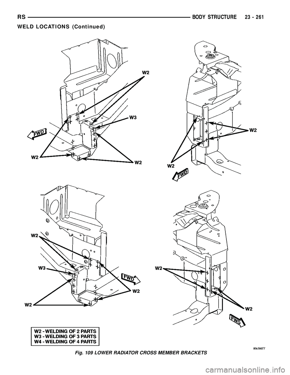
Fig. 109 LOWER RADIATOR CROSS MEMBER BRACKETS
RSBODY STRUCTURE23 - 261
WELD LOCATIONS (Continued)
Page 2152 of 2339
HEATING & AIR CONDITIONING
TABLE OF CONTENTS
page page
HEATING & AIR CONDITIONING
DESCRIPTION
ENGINE COOLING SYSTEM
REQUIREMENTS.......................1
HEATER AND AIR CONDITIONER..........1
MANUAL SINGLE ZONE.................2
MANUAL DUAL ZONE...................2
MANUAL THREE ZONE..................2
AUTOMATIC TEMPERATURE CONTROL....3
OPERATION
HEATER AND AIR CONDITIONER..........4
MANUAL SINGLE ZONE.................4
MANUAL DUAL ZONE...................5
MANUAL THREE ZONE..................5AUTOMATIC TEMPERATURE CONTROL....5
DIAGNOSIS AND TESTING
A/C COOL DOWN TEST.................6
A/C PERFORMANCE TEST...............7
HEATER PERFORMANCE TEST..........10
SPECIFICATIONS
A/C SYSTEM.........................11
CONTROLS - FRONT.....................13
CONTROLS - REAR......................33
DISTRIBUTION - FRONT...................42
DISTRIBUTION - REAR....................56
PLUMBING - FRONT.....................64
PLUMBING - REAR......................98
CABIN HEATER........................113
HEATING & AIR
CONDITIONING
DESCRIPTION
ENGINE COOLING SYSTEM REQUIREMENTS
To maintain the performance level of the heating,
ventilation and air conditioning (HVAC) system, the
engine cooling system must be properly maintained.
The use of a bug screen is not recommended. Any
obstructions in front of the radiator or condenser will
reduce the performance of the air conditioning and
engine cooling systems.
The engine cooling system includes the radiator,
thermostat, radiator hoses and the engine coolant
pump. Refer to Cooling for more information before
opening or attempting any service to the engine cool-
ing system.
HEATER AND AIR CONDITIONER
A manually controlled single zone type heating-air
conditioning system, manually controlled dual zone
type heating-air conditioning system, manually con-
trolled three zone type heating-air conditioning sys-
tem or an automatic controlled three zone type
heating-air conditioning system is available on this
model.
All vehicles are equipped with a common heater,
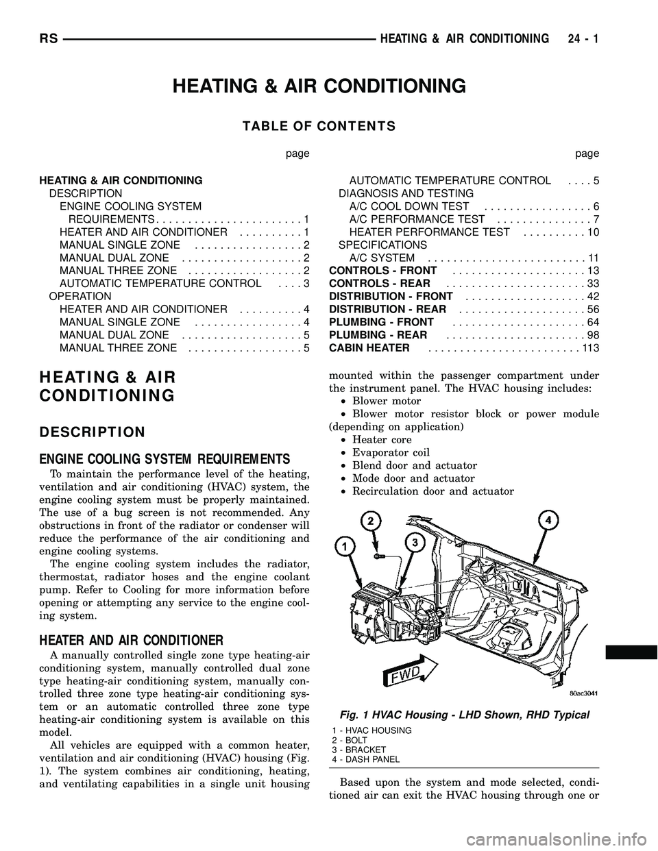
ventilation and air conditioning (HVAC) housing (Fig.
1). The system combines air conditioning, heating,
and ventilating capabilities in a single unit housingmounted within the passenger compartment under
the instrument panel. The HVAC housing includes:
²Blower motor
²Blower motor resistor block or power module
(depending on application)
²Heater core
²Evaporator coil
²Blend door and actuator
²Mode door and actuator
²Recirculation door and actuator
Based upon the system and mode selected, condi-
tioned air can exit the HVAC housing through one or
Fig. 1 HVAC Housing - LHD Shown, RHD Typical
1 - HVAC HOUSING
2 - BOLT
3 - BRACKET
4 - DASH PANEL
RSHEATING & AIR CONDITIONING24-1
Page 2160 of 2339
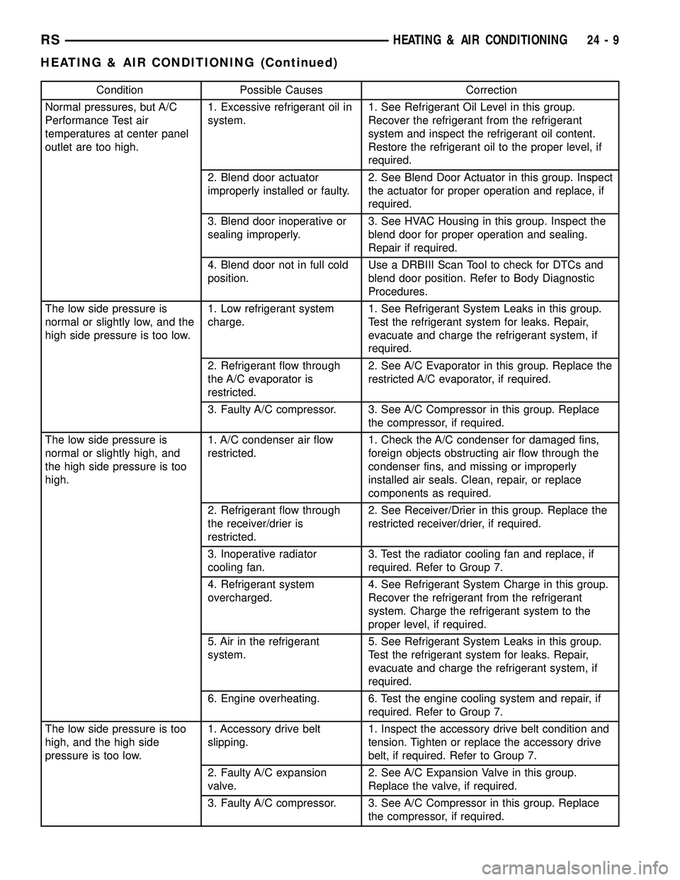
Condition Possible Causes Correction
Normal pressures, but A/C
Performance Test air
temperatures at center panel
outlet are too high.1. Excessive refrigerant oil in
system.1. See Refrigerant Oil Level in this group.
Recover the refrigerant from the refrigerant
system and inspect the refrigerant oil content.
Restore the refrigerant oil to the proper level, if
required.
2. Blend door actuator
improperly installed or faulty.2. See Blend Door Actuator in this group. Inspect
the actuator for proper operation and replace, if
required.
3. Blend door inoperative or
sealing improperly.3. See HVAC Housing in this group. Inspect the
blend door for proper operation and sealing.
Repair if required.
4. Blend door not in full cold
position.Use a DRBIII Scan Tool to check for DTCs and
blend door position. Refer to Body Diagnostic
Procedures.
The low side pressure is
normal or slightly low, and the
high side pressure is too low.1. Low refrigerant system
charge.1. See Refrigerant System Leaks in this group.
Test the refrigerant system for leaks. Repair,
evacuate and charge the refrigerant system, if
required.
2. Refrigerant flow through
the A/C evaporator is
restricted.2. See A/C Evaporator in this group. Replace the
restricted A/C evaporator, if required.
3. Faulty A/C compressor. 3. See A/C Compressor in this group. Replace
the compressor, if required.
The low side pressure is
normal or slightly high, and
the high side pressure is too
high.1. A/C condenser air flow
restricted.1. Check the A/C condenser for damaged fins,
foreign objects obstructing air flow through the
condenser fins, and missing or improperly
installed air seals. Clean, repair, or replace
components as required.
2. Refrigerant flow through
the receiver/drier is
restricted.2. See Receiver/Drier in this group. Replace the
restricted receiver/drier, if required.
3. Inoperative radiator
cooling fan.3. Test the radiator cooling fan and replace, if
required. Refer to Group 7.
4. Refrigerant system
overcharged.4. See Refrigerant System Charge in this group.
Recover the refrigerant from the refrigerant
system. Charge the refrigerant system to the
proper level, if required.
5. Air in the refrigerant
system.5. See Refrigerant System Leaks in this group.
Test the refrigerant system for leaks. Repair,
evacuate and charge the refrigerant system, if
required.
6. Engine overheating. 6. Test the engine cooling system and repair, if
required. Refer to Group 7.
The low side pressure is too
high, and the high side
pressure is too low.1. Accessory drive belt
slipping.1. Inspect the accessory drive belt condition and
tension. Tighten or replace the accessory drive
belt, if required. Refer to Group 7.
2. Faulty A/C expansion
valve.2. See A/C Expansion Valve in this group.
Replace the valve, if required.
3. Faulty A/C compressor. 3. See A/C Compressor in this group. Replace
the compressor, if required.
RSHEATING & AIR CONDITIONING24-9
HEATING & AIR CONDITIONING (Continued)
Page 2161 of 2339
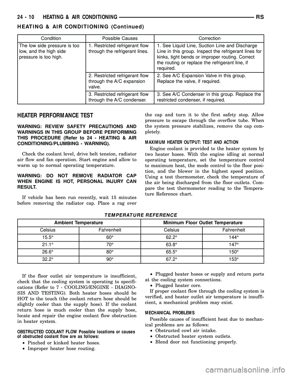
Condition Possible Causes Correction
The low side pressure is too
low, and the high side
pressure is too high.1. Restricted refrigerant flow
through the refrigerant lines.1. See Liquid Line, Suction Line and Discharge
Line in this group. Inspect the refrigerant lines for
kinks, tight bends or improper routing. Correct
the routing or replace the refrigerant line, if
required.
2. Restricted refrigerant flow
through the A/C expansion
valve.2. See A/C Expansion Valve in this group.
Replace the valve, if required.
3. Restricted refrigerant flow
through the A/C condenser.3. See A/C Condenser in this group. Replace the
restricted condenser, if required.
HEATER PERFORMANCE TEST
WARNING: REVIEW SAFETY PRECAUTIONS AND
WARNINGS IN THIS GROUP BEFORE PERFORMING
THIS PROCEDURE (Refer to 24 - HEATING & AIR
CONDITIONING/PLUMBING - WARNING).
Check the coolant level, drive belt tension, radiator
air flow and fan operation. Start engine and allow to
warm up to normal operating temperature.
WARNING: DO NOT REMOVE RADIATOR CAP
WHEN ENGINE IS HOT, PERSONAL INJURY CAN
RESULT.
If vehicle has been run recently, wait 15 minutes
before removing the radiator cap. Place a rag overthe cap and turn it to the first safety stop. Allow
pressure to escape through the overflow tube. When
the system pressure stabilizes, remove the cap com-
pletely.
MAXIMUM HEATER OUTPUT: TEST AND ACTION
Engine coolant is provided to the heater system by
two heater hoses. With the engine idling at normal
operating temperature, set the temperature control
to maximum heat, the mode control to the floor posi-
tion, and the blower in the highest speed position.
Using a test thermometer, check the temperature of
the air being discharged from the floor outlets. Com-
pare the test thermometer reading to the Tempera-
ture Reference chart.
TEMPERATURE REFERENCE
Ambient Temperature Minimum Floor Outlet Temperature
Celsius Fahrenheit Celsius Fahrenheit
15.5É 60É 62.2É 144É
21.1É 70É 63.8É 147É
26.6É 80É 65.5É 150É
32.2É 90É 67.2É 153É
If the floor outlet air temperature is insufficient,
check that the cooling system is operating to specifi-
cations (Refer to 7 - COOLING/ENGINE - DIAGNO-
SIS AND TESTING). Both heater hoses should be
HOT to the touch (the coolant return hose should be
slightly cooler than the supply hose). If the coolant
return hose is much cooler than the supply hose,
locate and repair the engine coolant flow obstruction
in heater system.
OBSTRUCTED COOLANT FLOW Possible locations or causes
of obstructed coolant flow are as follows:
²Pinched or kinked heater hoses.
²Improper heater hose routing.²Plugged heater hoses or supply and return ports
at the cooling system connections.
²Plugged heater core.
If proper coolant flow through the cooling system is
verified, and heater outlet air temperature is insuffi-
cient, a mechanical problem may exist.
MECHANICAL PROBLEMS
Possible causes of insufficient heat due to mechan-
ical problems are as follows:
²Obstructed cowl air intake.
²Obstructed heater system outlets.
²Blend door not functioning properly.
24 - 10 HEATING & AIR CONDITIONINGRS
HEATING & AIR CONDITIONING (Continued)
Page 2171 of 2339
REMOVAL
WARNING: ON VEHICLES EQUIPPED WITH AIR-
BAGS, DISABLE THE AIRBAG SYSTEM BEFORE
ATTEMPTING ANY STEERING WHEEL, STEERING
COLUMN, OR INSTRUMENT PANEL COMPONENT
DIAGNOSIS OR SERVICE. DISCONNECT AND ISO-
LATE THE BATTERY NEGATIVE (GROUND) CABLE,
THEN WAIT TWO MINUTES FOR THE AIRBAG SYS-
TEM CAPACITOR TO DISCHARGE BEFORE PER-
FORMING FURTHER DIAGNOSIS OR SERVICE. THIS
IS THE ONLY SURE WAY TO DISABLE THE AIRBAG
SYSTEM. FAILURE TO TAKE THE PROPER PRE-
CAUTIONS COULD RESULT IN ACCIDENTAL AIR-
BAG DEPLOYMENT AND POSSIBLE PERSONAL
INJURY.
(1) Disconnect and isolate the battery negative
cable.
(2) Remove the center bezel from the instrument
panel (Refer to 23 - BODY/INSTRUMENT PANEL/
INSTRUMENT PANEL CENTER BEZEL -
REMOVAL).
(3) Place the instrument panel center bezel unit
face down on a suitable work surface. Take the
proper precautions to protect the center bezel from
cosmetic damage.
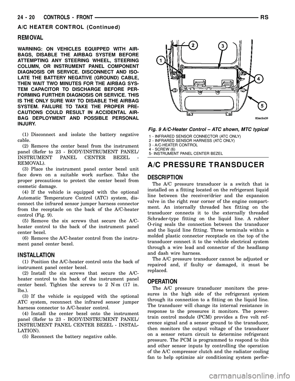
(4) If the vehicle is equipped with the optional
Automatic Temperature Control (ATC) system, dis-
connect the infrared sensor jumper harness connector
from the receptacle on the back of the A/C-heater
control (Fig. 9).
(5) Remove the six screws that secure the A/C-
heater control to the back of the instrument panel
center bezel.
(6) Remove the A/C-heater control from the instru-
ment panel center bezel.
INSTALLATION
(1) Position the A/C-heater control onto the back of
instrument panel center bezel.
(2) Install the six screws that secure the A/C-
heater control to the back of the instrument panel
center bezel. Tighten the screws to 2 N´m (17 in.
lbs.).
(3) If the vehicle is equipped with the optional
ATC system, reconnect the infrared sensor jumper
harness connector to A/C-heater control.
(4) Install the center bezel onto the instrument
panel (Refer to 23 - BODY/INSTRUMENT PANEL/
INSTRUMENT PANEL CENTER BEZEL - INSTAL-
LATION).
(5) Reconnect the battery negative cable.
A/C PRESSURE TRANSDUCER
DESCRIPTION
The A/C pressure transducer is a switch that is
installed on a fitting located on the refrigerant liquid
line between the receiver/drier and the expansion
valve in the right rear corner of the engine compart-
ment. An internally threaded hex fitting on the
transducer connects it to the externally threaded
Schrader-type fitting on the liquid line. A rubber
O-ring seals the connection between the transducer
and the liquid line fitting. Three terminals within a
molded plastic connector receptacle on the top of the
transducer connect it to the vehicle electrical system
through a wire lead and connector of the headlamp
and dash wire harness.
The A/C pressure transducer cannot be adjusted or
repaired and, if faulty or damaged, it must be
replaced.
OPERATION
The A/C pressure transducer monitors the pres-
sures in the high side of the refrigerant system
through its connection to a fitting on the liquid line.
The transducer will change its internal resistance in
response to the pressures it monitors. The power-
train control module (PCM) provides a five volt ref-
erence signal and a sensor ground to the transducer,
then monitors the output voltage of the transducer
on a sensor return circuit to determine refrigerant
pressure. The PCM is programmed to respond to this
and other sensor inputs by controlling the operation
of the A/C compressor clutch and the radiator cooling
fan to help optimize air conditioning system perfor-
Fig. 9 A/C-Heater Control ± ATC shown, MTC typical
1 - INFRARED SENSOR CONNECTOR (ATC ONLY)
2 - INFRARED SENSOR HARNESS (ATC ONLY)
3 - A/C-HEATER CONTROL
4 - SCREW (6)
5- INSTRUMENT PANEL CENTER BEZEL
24 - 20 CONTROLS - FRONTRS
A/C HEATER CONTROL (Continued)