2005 CHRYSLER CARAVAN brake fluid
[x] Cancel search: brake fluidPage 750 of 2339

8W-35 ANTILOCK BRAKES
Component Page
Body Control Module................. 8W-35-2
Brake Fluid Level Switch.............. 8W-35-3
Brake Lamp Switch.................. 8W-35-3
Clutch Pedal Interlock Switch.......... 8W-35-3
Controller Antilock Brake.......... 8W-35-2, 3, 4
Engine Control Module................ 8W-35-3
Front Control Module................. 8W-35-3
Fuse 9............................ 8W-35-2
Fuse 21............................ 8W-35-2
Fuse 26............................ 8W-35-3
G100.............................. 8W-35-2Component Page
G200.............................. 8W-35-2
G300.............................. 8W-35-3
Integrated Power Module............ 8W-35-2, 3
Left Front Wheel Speed Sensor......... 8W-35-4
Left Rear Wheel Speed Sensor.......... 8W-35-4
Powertrain Control Module............ 8W-35-3
Right Front Wheel Speed Sensor........ 8W-35-4
Right Rear Wheel Speed Sensor......... 8W-35-4
Traction Control Switch............... 8W-35-2
Transmission Control Module........... 8W-35-3
RS8W-35 ANTILOCK BRAKES8W-35-1
Page 970 of 2339

8W-80 CONNECTOR PIN-OUTS
Component Page
A/C Compressor Clutch............... 8W-80-6
A/C Pressure Sensor.................. 8W-80-6
A/C-Heater Control C1 (MTC).......... 8W-80-6
A/C-Heater Control C2 (MTC).......... 8W-80-7
Accelerator Pedal Position Sensor
(Diesel).......................... 8W-80-7
Adjustable Pedals Motor
(Except Export)................... 8W-80-7
Adjustable Pedals Relay (Except
Export/Except Memory)............. 8W-80-8
Adjustable Pedals Sensor
(Except Export)................... 8W-80-8
Adjustable Pedals Switch
(Except Export)................... 8W-80-8
Ambient Temperature Sensor........... 8W-80-8
Amplifier C1 (Highline Audio).......... 8W-80-9
Amplifier C2 (Highline Audio).......... 8W-80-9
ATC Remote Sensor (ATC)............ 8W-80-10
Auto Temp Control C1............... 8W-80-10
Auto Temp Control C2............... 8W-80-10
Auto Temp Control C3............... 8W-80-11
Back-Up Lamp Switch (MTX).......... 8W-80-11
Battery Temperature Sensor........... 8W-80-11
Belt Tension Sensor
(Occupant Sensing)................ 8W-80-11
Blower Motor Resistor C1 (MTC)....... 8W-80-12
Blower Motor Resistor C2 (MTC)....... 8W-80-12
Body Control Module C1.............. 8W-80-12
Body Control Module C2.............. 8W-80-13
Body Control Module C3.............. 8W-80-14
Body Control Module C4.............. 8W-80-15
Body Control Module C5.............. 8W-80-16
Boost Pressure Sensor (Diesel)......... 8W-80-16
Brake Fluid Level Switch............. 8W-80-17
Brake Lamp Switch................. 8W-80-17
Brake Transmission Shift Interlock
Solenoid........................ 8W-80-17
C100............................. 8W-80-17
C100............................. 8W-80-18
C101 (Diesel)...................... 8W-80-18
C101 (Diesel)...................... 8W-80-19
C101 (Gas)........................ 8W-80-19
C101 (Gas)........................ 8W-80-19
C102 (Gas)........................ 8W-80-19
C102 (Gas)........................ 8W-80-20
C103 (Diesel)...................... 8W-80-20
C103 (Diesel)...................... 8W-80-20
C104 (Except Export)................ 8W-80-20
C104 (Except Export)................ 8W-80-21
C106 (Export)...................... 8W-80-21
C106 (Export)...................... 8W-80-21
C107 (Export)...................... 8W-80-21Component Page
C107 (Export)...................... 8W-80-22
C111(EATX)....................... 8W-80-22
C111(EATX)....................... 8W-80-22
C112 (Gas)........................ 8W-80-22
C112 (Gas)........................ 8W-80-22
C200............................. 8W-80-23
C200............................. 8W-80-25
C202............................. 8W-80-27
C202............................. 8W-80-27
C204 (Premium).................... 8W-80-27
C204 (Premium).................... 8W-80-28
C206 (Except Base).................. 8W-80-28
C206 (Except Base).................. 8W-80-28
C207 (DVD)....................... 8W-80-28
C207 (Hands Free).................. 8W-80-29
C300 (LHD)....................... 8W-80-29
C300 (LHD)....................... 8W-80-29
C300 (RHD)....................... 8W-80-30
C300 (RHD)....................... 8W-80-30
C301 (Luxury/Export)................ 8W-80-30
C301 (Luxury/Export)................ 8W-80-30
C302 (Export)...................... 8W-80-31
C302 (Export)...................... 8W-80-31
C302 (Luxury/Except Export).......... 8W-80-31
C302 (Luxury/Except Export).......... 8W-80-31
C303 (LHD)....................... 8W-80-32
C303 (LHD)....................... 8W-80-32
C303 (RHD)....................... 8W-80-32
C303 (RHD)....................... 8W-80-33
C304 (LHD)....................... 8W-80-33
C304 (LHD)....................... 8W-80-33
C305............................. 8W-80-33
C305............................. 8W-80-34
C306 (RHD)....................... 8W-80-34
C306 (RHD)....................... 8W-80-34
C307............................. 8W-80-34
C307............................. 8W-80-35
C308 (Except Side Airbag)............ 8W-80-35
C308 (Side Airbag).................. 8W-80-35
C308 (Except Side Airbag)............ 8W-80-36
C308 (Side Airbag).................. 8W-80-36
C309 (Side Airbag).................. 8W-80-36
C309 (Side Airbag).................. 8W-80-37
C309 (Except Side Airbag)............ 8W-80-37
C309 (Except Side Airbag)............ 8W-80-37
C310 (Front Console)................ 8W-80-38
C310 (Front Console)................ 8W-80-38
C311 (3 Zone HVAC/Except
Side Airbag)..................... 8W-80-38
C311 (3 Zone HVAC/Except
Side Airbag)..................... 8W-80-38
C311 (3 Zone HVAC/Side Airbag)....... 8W-80-39
RS8W-80 CONNECTOR PIN-OUTS8W-80-1
Page 986 of 2339

BRAKE FLUID LEVEL SWITCH-2WAY
CAV CIRCUIT FUNCTION
1 B20 20DG/OR BRAKE FLUID LEVEL SWITCH SENSE
2 Z420 20BK/OR GROUND
BRAKE LAMP SWITCH - BLACK 6 WAY
CAV CIRCUIT FUNCTION
1 A103 18GY/RD FUSED B(+)
2 L50 18WT/TN (DIESEL) PRIMARY BRAKE SWITCH SIGNAL
2 L50 18WT/TN (GAS) BRAKE LAMP SWITCH OUTPUT
3 V30 20VT/WT (GAS) S/C BRAKE SWITCH OUTPUT
4 V32 20VT/YL (GAS) SPEED CONTROL SUPPLY
5 Z429 20BK/OR GROUND
6 B29 20DG/WT SECONDARY BRAKE SWITCH SIGNAL
BRAKE TRANSMISSION SHIFT INTERLOCK SOLENOID - BLACK 2 WAY
CAV CIRCUIT FUNCTION
1 K32 18DB/YL BRAKE TRANSMISSION SHIFT INTERLOCK SOLENOID
CONTROL
2 F2 18PK/YL FCM OUTPUT (UNLOCK-RUN-START)
C100 - BLACK (BODY SIDE)
CAV CIRCUIT
1 D21 20WT/DG
2 D123 20WT/BR
3 D15 20DG/YL (DIESEL)
3 D20 20WT/LG (GAS)
4 R80 20VT/LB (DIESEL)
4 T141 20YL/OR (GAS MTX EXPORT)
5 Z111 20BK/WT
6 N1 16DB/OR (DIESEL)
6 G31 18VT/LG (GAS/EXCEPT SIDE AIRBAG)
6 G31 18WT/LG (GAS/SIDE AIRBAG)
7 N2 18DB/YL (DIESEL)
7 D15 20DG/YL (GAS)
8 K22 20OR/DB (DIESEL)
8 V32 20VT/YL (GAS)
9 B29 20DG/WT
10 V37 20VT
11 R82 20WT/LB (DIESEL)
11 V30 20VT/WT (GAS)
12 K900 20DB/DG
13 B1 18DG/OR (ABS)
14 B2 18DG/LB (ABS)
RS8W-80 CONNECTOR PIN-OUTS8W-80-17
Page 1041 of 2339
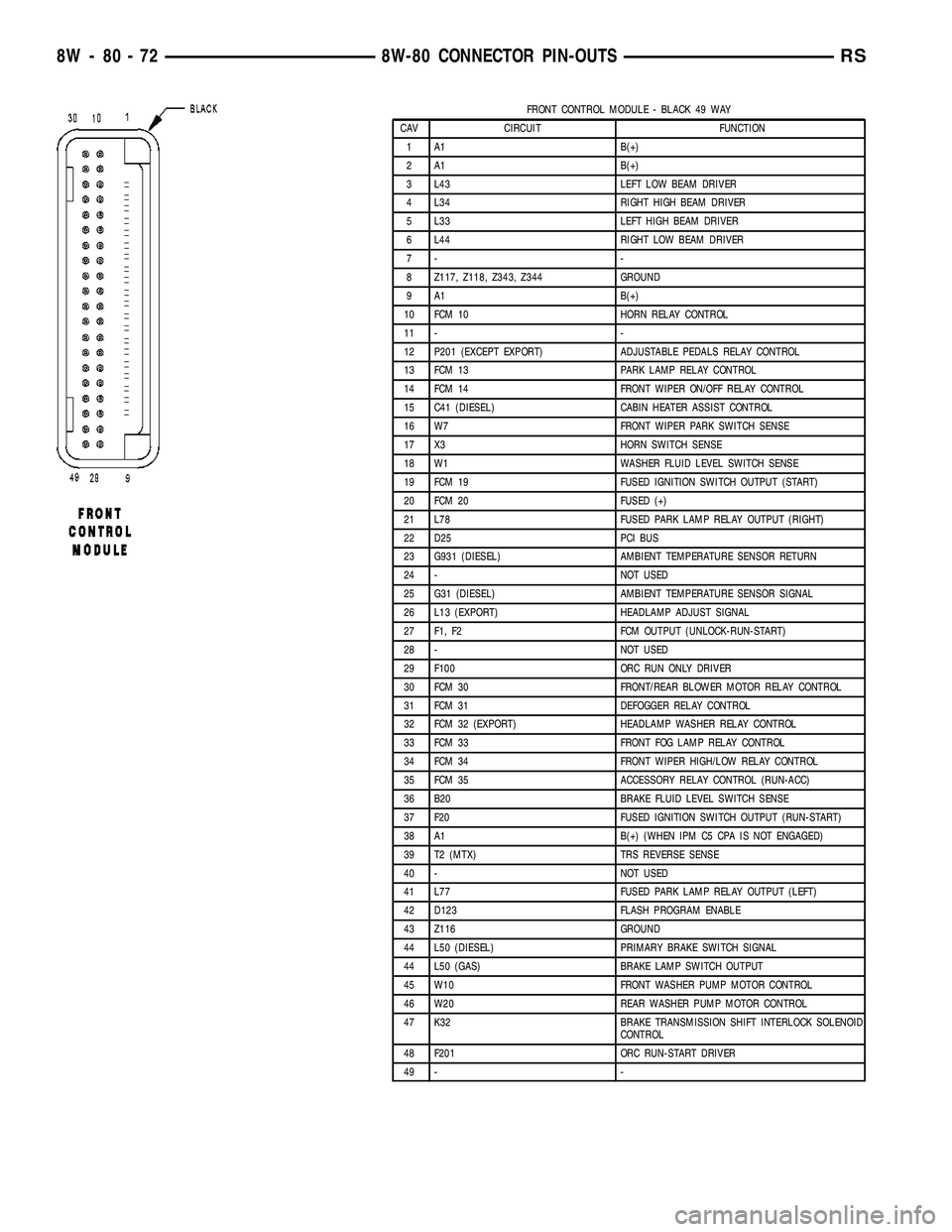
FRONT CONTROL MODULE - BLACK 49 WAY
CAV CIRCUIT FUNCTION
1 A1 B(+)
2 A1 B(+)
3 L43 LEFT LOW BEAM DRIVER
4 L34 RIGHT HIGH BEAM DRIVER
5 L33 LEFT HIGH BEAM DRIVER
6 L44 RIGHT LOW BEAM DRIVER
7- -
8 Z117, Z118, Z343, Z344 GROUND
9 A1 B(+)
10 FCM 10 HORN RELAY CONTROL
11 - -
12 P201 (EXCEPT EXPORT) ADJUSTABLE PEDALS RELAY CONTROL
13 FCM 13 PARK LAMP RELAY CONTROL
14 FCM 14 FRONT WIPER ON/OFF RELAY CONTROL
15 C41 (DIESEL) CABIN HEATER ASSIST CONTROL
16 W7 FRONT WIPER PARK SWITCH SENSE
17 X3 HORN SWITCH SENSE
18 W1 WASHER FLUID LEVEL SWITCH SENSE
19 FCM 19 FUSED IGNITION SWITCH OUTPUT (START)
20 FCM 20 FUSED (+)
21 L78 FUSED PARK LAMP RELAY OUTPUT (RIGHT)
22 D25 PCI BUS
23 G931 (DIESEL) AMBIENT TEMPERATURE SENSOR RETURN
24 - NOT USED
25 G31 (DIESEL) AMBIENT TEMPERATURE SENSOR SIGNAL
26 L13 (EXPORT) HEADLAMP ADJUST SIGNAL
27 F1, F2 FCM OUTPUT (UNLOCK-RUN-START)
28 - NOT USED
29 F100 ORC RUN ONLY DRIVER
30 FCM 30 FRONT/REAR BLOWER MOTOR RELAY CONTROL
31 FCM 31 DEFOGGER RELAY CONTROL
32 FCM 32 (EXPORT) HEADLAMP WASHER RELAY CONTROL
33 FCM 33 FRONT FOG LAMP RELAY CONTROL
34 FCM 34 FRONT WIPER HIGH/LOW RELAY CONTROL
35 FCM 35 ACCESSORY RELAY CONTROL (RUN-ACC)
36 B20 BRAKE FLUID LEVEL SWITCH SENSE
37 F20 FUSED IGNITION SWITCH OUTPUT (RUN-START)
38 A1 B(+) (WHEN IPM C5 CPA IS NOT ENGAGED)
39 T2 (MTX) TRS REVERSE SENSE
40 - NOT USED
41 L77 FUSED PARK LAMP RELAY OUTPUT (LEFT)
42 D123 FLASH PROGRAM ENABLE
43 Z116 GROUND
44 L50 (DIESEL) PRIMARY BRAKE SWITCH SIGNAL
44 L50 (GAS) BRAKE LAMP SWITCH OUTPUT
45 W10 FRONT WASHER PUMP MOTOR CONTROL
46 W20 REAR WASHER PUMP MOTOR CONTROL
47 K32 BRAKE TRANSMISSION SHIFT INTERLOCK SOLENOID
CONTROL
48 F201 ORC RUN-START DRIVER
49 - -
8W - 80 - 72 8W-80 CONNECTOR PIN-OUTSRS
Page 1053 of 2339
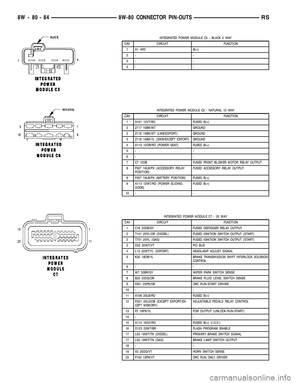
INTEGRATED POWER MODULE C5 - BLACK 4 WAY
CAV CIRCUIT FUNCTION
1 A1 4RD B(+)
2- -
3- -
4- -
INTEGRATED POWER MODULE C6 - NATURAL 10 WAY
CAV CIRCUIT FUNCTION
1 A101 12VT/RD FUSED B(+)
2 Z117 16BK/WT GROUND
3 Z118 16BK/WT (LWB/EXPORT) GROUND
3 Z118 16BK/YL (SWB/EXCEPT EXPORT) GROUND
4 A110 12OR/RD (POWER SEAT) FUSED B(+)
5- -
6- -
7 C7 12DB FUSED FRONT BLOWER MOTOR RELAY OUTPUT
8 F307 18LB/PK (ACCESSORY RELAY
POSITION)FUSED ACCESSORY RELAY OUTPUT
8 F307 18LB/PK (BATTERY POSITION) FUSED B(+)
9 A113 12WT/RD (POWER SLIDING
DOOR)FUSED B(+)
10 - -
INTEGRATED POWER MODULE C7 - 20 WAY
CAV CIRCUIT FUNCTION
1 C16 20DB/GY FUSED DEFOGGER RELAY OUTPUT
2 T141 20YL/OR (DIESEL) FUSED IGNITION SWITCH OUTPUT (START)
2 T751 20YL (GAS) FUSED IGNITION SWITCH OUTPUT (START)
3 D25 20WT/VT PCI BUS
4 L13 20WT/YL (EXPORT) HEADLAMP ADJUST SIGNAL
5 K32 18DB/YL BRAKE TRANSMISSION SHIFT INTERLOCK SOLENOID
CONTROL
6- -
7 W7 20BR/GY WIPER PARK SWITCH SENSE
8 B20 20DG/OR BRAKE FLUID LEVEL SWITCH SENSE
9 F201 20PK/OR ORC RUN-START DRIVER
10 - -
11 A106 20LB/RD FUSED B(+)
12 P201 20LG/DB (EXCEPT EXPORT/EX-
CEPT MEMORY)ADJUSTABLE PEDALS RELAY CONTROL
13 F2 18PK/YL FCM OUTPUT (UNLOCK-RUN-START)
14 - -
15 A114 16GY/RD FUSED B(+) (I.O.D.)
16 D123 20WT/BR FLASH PROGRAM ENABLE
17 L50 18WT/TN (DIESEL) PRIMARY BRAKE SWITCH SIGNAL
17 L50 18WT/TN (GAS) BRAKE LAMP SWITCH OUTPUT
18 - -
19 X3 20DG/VT HORN SWITCH SENSE
20 F100 18PK/VT ORC RUN ONLY DRIVER
8W - 80 - 84 8W-80 CONNECTOR PIN-OUTSRS
Page 1125 of 2339
CONNECTOR NAME/NUMBER COLOR LOCATION FIG.
Right Sliding Door Motor BK At Sliding Door 45
Right Speed Control Switch WT At Steering Wheel N/S
Right Turn Signal Lamp (Export) OR At Lamp N/S
Right Visor/Vanity Lamp BK At Lamp N/S
Sentry Key Remote Entry Module
(SKREEM)BK At Steering Column 20, 21, 22, 23, 31
Siren (United Kingdom) BK Left Front Body N/S
Speed Control Servo (Gas) BK Near Controller Antilock Brake 11, 17, 18
Sunroof Module (Except Export) BK At Sunroof N/S
Sunroof Switch (Except Export) NAT Near Overhead Console N/S
Thatcham Alarm Module (United
Kingdom)BK Top Right Side of Instrument Panel
Near SpeakerN/S
Throttle Position Sensor (Gas) GY On Throttle Body 10, 11, 17
Traction Control Switch BK Rear of Swtich 21, 22, 31
Trailer Tow Connector (Except
Export)Left Quarter Panel N/S
Transmission Control Relay
(Diesel)Near Transmission 16
Transmission Range Sensor DKGY Top of Transmission 14, 19
Transmission Solenoid/Pressure
Switch AssemblyBK Side of Transmission 14, 19
Vehicle Speed Sensor (MTX) BK Rear of Transmission 16
Washer Fluid Level Switch BK Bottom of Reservoir 3
Washer Pump Motor BK Right Fender Well 3
Water in Fuel Sensor (Diesel) BK Left Rear Engine Compartment N/S
Wiper Module DKGY Left Side Cowl 6
GROUNDS
GROUND NUMBER LOCATION FIG.
G100 Body Ground Near Powertrain Control Module N/S
G101 Above Starter 13, 15, 18
G102 Left Headlamp Area 1
G103 Above Starter 15
G200 Left Side of Instrument Panel 20, 21 29
G201 Right Side of Instrument Panel 20, 24, 29
G202 Near Radio N/S
G300 Left B Pillar 32
G301 Right B Pillar 33, 39
G302 Left Rear Quarter 47
G303 Liftgate Ground 49
8W - 91 - 12 8W-91 CONNECTOR/GROUND/SPLICE LOCATIONRS
CONNECTOR/GROUND/SPLICE LOCATION (Continued)
Page 1326 of 2339
INSPECTION
Check manifold for:
²Damage and cracks.
²Mounting surface distortion by using a straight-
edge and thickness gauge.
INSTALLATION - UPPER INTAKE MANIFOLD
(1) If the following components were removed from
manifold, install and tighten to specifications:
CAUTION: The special screws used for the compos-
ite manifold attached components must be installed
slowly using hand tools only. This requirement is to
prevent the melting of material that causes stripped
threads. If threads become stripped, an oversize
repair screw is available. For more information and
procedure (Refer to 9 - ENGINE/MANIFOLDS/IN-
TAKE MANIFOLD - STANDARD PROCEDURE - MAN-
IFOLD STRIPPED THREAD REPAIR).
²MAP sensor - 1.7 N´m (15 in. lbs.)
²Throttle cable bracket - 5.6 N´m (50 in. lbs.)
(2) Remove covering on lower intake manifold and
clean surfaces.
(3) Inspect manifold gasket condition. Gaskets can
be re-used, if not damaged. To replace, remove gasket
from upper manifold (Fig. 118). Position new gasket
in seal channel and press lightly in-place. Repeat
procedure for each gasket position.
(4) Position upper manifold on lower manifold (Fig.
118). Apply MopartLock & Seal Adhesive (Medium
Strength Threadlocker) to each upper intake mani-
fold bolt. Install and tighten bolts to 12 N´m (105 in.
lbs.) following torque sequence in (Fig. 119).
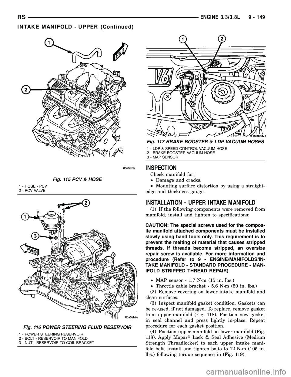
Fig. 115 PCV & HOSE
1 - HOSE - PCV
2 - P C V VA LV E
Fig. 116 POWER STEERING FLUID RESERVOIR
1 - POWER STEERING RESERVOIR
2 - BOLT - RESERVOIR TO MANIFOLD
3 - NUT - RESERVOIR TO COIL BRACKET
Fig. 117 BRAKE BOOSTER & LDP VACUUM HOSES
1 - LDP & SPEED CONTROL VACUUM HOSE
2 - BRAKE BOOSTER VACUUM HOSE
3 - MAP SENSOR
RSENGINE 3.3/3.8L9 - 149
INTAKE MANIFOLD - UPPER (Continued)
Page 1362 of 2339
REMOVAL
The front cradle crossmember must be installed in
the design location to achieve proper front end sus-
pension alignment. If the cradle crossmember is
removed without applying reference marks on the
frame rails, align the cradle crossmember according
to the dimensions provided in this group.
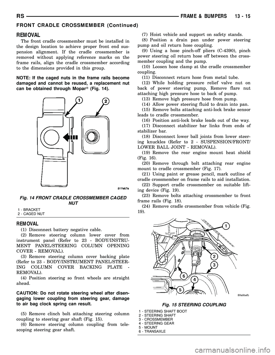
NOTE: If the caged nuts in the frame rails become
damaged and cannot be reused, a replacement nut
can be obtained through MoparT(Fig. 14).
REMOVAL
(1) Disconnect battery negative cable.
(2) Remove steering column lower cover from
instrument panel (Refer to 23 - BODY/INSTRU-
MENT PANEL/STEERING COLUMN OPENING
COVER - REMOVAL).
(3) Remove steering column cover backing plate
(Refer to 23 - BODY/INSTRUMENT PANEL/STEER-
ING COLUMN COVER BACKING PLATE -
REMOVAL).
(4) Position steering so front wheels are straight
ahead.
CAUTION: Do not rotate steering wheel after disen-
gaging lower coupling from steering gear, damage
to air bag clock spring can result.
(5) Remove clinch bolt attaching steering column
coupling to steering gear shaft (Fig. 15).
(6) Remove steering column coupling from tele-
scoping steering gear shaft.(7) Hoist vehicle and support on safety stands.
(8) Position a drain pan under power steering
pump and oil return hose coupling.
(9) Using a hose pinch-off pliers (C-4390), pinch
power steering oil return hose off between the cross-
member coupling and the pump.
(10) Loosen hose clamp at the cradle crossmember
coupling.
(11) Disconnect return hose from metal tube.
(12) While holding pressure relief valve nut on
back of power steering pump, Remove flare nut
attaching high pressure hose to back of pump.
(13) Remove high pressure hose from pump.
(14) Allow power steering fluid to drain into pan.
(15) Remove bolts attaching anti-lock brake sensor
leads to cradle crossmember.
(16) Position anti-lock brake leads out of the way.
(17) Disconnect stabilizer bar links from ends of
stabilizer bar.
(18) Disconnect lower ball joints from lower steer-
ing knuckles (Refer to 2 - SUSPENSION/FRONT/
LOWER BALL JOINT - REMOVAL).
(19) Remove the rear engine mount heat shield
(Fig. 16).
(20) Remove through bolt attaching rear engine
mount to cradle crossmember (Fig. 17).
(21) Using paint or grease pencil, mark outline of
cradle crossmember on frame rails to aid installation.
(22) Support cradle crossmember on suitable lift-
ing device (Fig. 19).
(23) Remove bolts attaching crossmember to front
frame rails (Fig. 18).
(24) Remove cradle crossmember from vehicle (Fig.
19).
Fig. 14 FRONT CRADLE CROSSMEMBER CAGED
NUT
1 - BRACKET
2 - CAGED NUT
Fig. 15 STEERING COUPLING
1 - STEERING SHAFT BOOT
2 - STEERING SHAFT
3 - CROSSMEMBER
4 - STEERING GEAR
5 - MOUNT
6 - TRANSAXLE
RSFRAME & BUMPERS13-15
FRONT CRADLE CROSSMEMBER (Continued)