2005 BMW X5 light
[x] Cancel search: lightPage 4 of 48

M54 ENGINE
Mechanical Changes
In addition to the increased displacement of the M54B30 engine, several mechanical
changes were incorporated into the engine for reduced emissions and increased fuel econ-
omy. These changes include:
• NEW PISTONS - The piston has a shorter skirt compared to the M52 TU and continues
with the graphite coating for friction and emission reducing measures. The piston rings have
been modified to reduce friction.
• CRANKSHAFT - The crankshaft for the 3 liter M54 is adopted from the S52B32 - M3
engine.
• CAMSHAFT - The camshaft for the 3 liter M54 is modified with more lift (9.7 mm) and
new valve springs to accommodate the increased lift.
• INTAKE MANIFOLD - The intake manifold is modified with shorter ram tubes (20mm
shorter on 3 liter. The diameter of the tubes is increased slightly.
• INJECTION VALVES - The diameter of the injection pintle has increased slightly for the
increased displacement of the 3 liter engine.
4
M54engMS43/ST036/6/2000
ART-0198U29
ART-INJECTOR
Page 14 of 48

14
M54engMS43/ST036/6/2000
MS 43 NEW FUNCTIONS
EDK THROTTLE POSITION FEEDBACK SIGNALS
EDK FEEDBACK SIGNAL MONITORING & EDK FAILSAFE OPERATION:
• The EDK provides two separate signals from two integral potentiometers (Pot 1 and Pot
2) representing the exact position of the throttle plate.
• EDK Pot 1 provides the primary throttle plate position feedback. As a redundant safe-
ty feature, Pot 2 is continuously cross checked with Pot 1 for signal plausibility.
• If plausibility errors are detected between Pot 1 and Pot 2, MS 43.0 will calculate the
inducted engine air mass (from HFM signal) and only utilize the potentiometer signal that
closely matches the detected intake air mass.
- The MS 43.0 uses the air mass signalling as a “virtual potentiometer” (pot 3) for a
comparative source to provide failsafe operation.
- If MS 43.0 cannot calculate a plausible conclusion from the monitored pots (1 or 2
and virtual 3) the EDK motor is switched off and fuel injection cut out is activated
(no failsafe operation possible).
• The EDK is continuously monitored during all phases of engine operation. It is also
briefly activated when KL 15 is initially switched on as a “pre-flight check” to verify it’s
mechanical integrity (no binding, appropriate return spring tension, etc). This is accom-
plished by monitoring both the motor control amperage and the reaction speed of the
EDK feedback potentiometers. If faults are detected the EDK motor is switched off and
fuel injection cut off is activated (no failsafe operation possible). The engine does how-
ever continue to run extremely rough at idle speed.
• When a replacement EDK is installed, the MS 43.0 adapts to the new component
(required amperage draw for motor control, feedback pot tolerance differences, etc).
This occurs immediately after the next cycle of KL 15 for approximately 30 seconds.
During this period of adaptation, the maximum opening of the throttle plate is 25%.
_____________________________________________________________________________
_____________________________________________________________________________
_____________________________________________________________________________
_____________________________________________________________________________
Page 25 of 48

25
M54engMS43/ST036/6/20000
OXYGEN SENSOR SIGNAL INFLUENCE ON INJECTOR “OPEN” TIME
The ECM monitors the:
• Amplitude of the signal (highest voltage or range sensor is producing)
• Switching time of the signal (how fast from lean to rich)
• Frequency of complete cycles (how many within a period of time)
These characteristics provide info to the ECM that reflect the overall condition of the sen-
sor.
POST CATALYTIC CONVERTER SENSOR SIGNAL
The post catalyst O2 sensors monitor the efficiency of the catalyst as a requirement of OBD
II. This signal also provides feedback of the pre-catalyst sensors efficiency and can cause
the ECM to “trim” the ms injection time to correct for slight deviations.
• If the catalyst is operating efficiently, most of the remaining oxygen in the exhaust gas
is burned (lack of O2 - “constant lean signal”).
The sensor signal fluctuates slightly in the higher end of the voltage scale.
• If the post sensor shows excessive fluctuations
(which echo the scope pattern of the pre
sensor), this indicates that the catalytic converter is not functioning correctly and cannot
consume the O2 (fault set).
• If the post sensor fluctuations move out of the normal voltage “window”, this indicates
that the pre sensor is not performing properly due toslight
deterioration. These systems
can also “trim” the ms injection time to compensate for this.
The constantly changing oxygen sensor input to the ECM is needed to correct the ms
injection time to ensure that the ideal air/fuel ratio is maintained.
Page 28 of 48

28
M54engMS43/ST036/6/2000
MISFIRE DETECTION
As part of the CARB/OBD regulations the engine control module must determine if misfire
is occurring and also identify the specific cylinder(s) and the severity of the misfire event,
and whether it is emissions relevant or catalyst damaging. In order to accomplish these
tasks the control module monitors the crankshaft for acceleration losses during firing seg-
ments of each cylinder based on firing order.
Misfire Detection Example: M54 (6 Cyl.) with Siemens System
The misfire/engine roughness calculation is derived from the differences in the period dura-
tion (T) of individual increment gear segments. Each segment period consist of an angular
range of 120° crank angle that starts 78° before Top Dead Center (TDC).
If the expected period duration is greater than the permissible value a misfire fault for the
particular cylinder is stored in the fault memory of the ECM. Depending on the level of mis-
fire rate measured the control unit will illuminate the "Service Engine Soon" light, may cut-
off fuel to the particular cylinder and may switch lambda operation to open-loop. All mis-
fire faults are weighted to determine if the misfire is emissions relevant or catalyst damag-
ing.
_________________________________________________________________
_________________________________________________________________
_________________________________________________________________
_________________________________________________________________
_________________________________________________________________
_________________________________________________________________
_________________________________________________________________
_________________________________________________________________
_________________________________________________________________
Page 29 of 48

29
M54engMS43/ST036/6/20000
EMISSIONS RELEVANT:
During an interval of 1000 crankshaft revolutions
the misfire events of all cylinders are
added and if the sum is greater than a predetermined value a fault will be set identifying the
particular cylinder(s). The “Service Engine Soon” light will be illuminated during and after
the second cycle if the fault is again present.
CATALYST DAMAGING:
During an interval of 200 crankshaft revolutions
the misfire events of all cylinders are added
and if the sum is greater than a predetermined value a fault will be set identifying the par-
ticular cylinders(s). The “Service Engine Soon” lamp:
• On vehicles with a Siemens Control Module (M54 engines) - the lamp will immediately go
to a steady illumination since fuel to the injector(s) is removed. Fuel cut-off to the cylin-
der will resume after several (
>>7) periods of decel if crankshaft sensor adaptation is suc-
cessfully completed or the engine is shut-off and restarted.
In each case the number of misfire events permitted is dependent on engine speed, load
and temperature map.
The process of misfire detection continues well after the diagnostic drive cycle requirements
have been completed. Misfire detection is an on-going monitoring process
that is only dis-
continued under certain conditions.
Misfire detection is only disabled under the following conditions:
___________________________________________________________________
___________________________________________________________________
___________________________________________________________________
REQUIREMENTSSTATUS/CONDITION
Engine Speed< 512 RPM
Engine LoadVarying/Unstable
Throttle AngleVarying/Unstable
TimingTiming retard request active (i.e. knock
control - ASC, AGS)
Engine Start-upUp to 5 seconds after start-up
A/CUp to 0.5 seconds after A/C activation
Decel fuel cut-offActive
Rough road recognitionActive
ASC ControlActive
Page 38 of 48

38
M54engMS43/ST036/6/2000
The Secondary Air Injection System is monitored via the use of the pre-catalyst oxygen sen-
sor(s). Once the air pump is active and is air injected into the system the signal at the oxy-
gen sensor will reflect a lean condition. If the oxygen sensor signal does not change with-
in a predefined time a fault will be set and identify the faulty bank(s). If after completing the
next cold start and a fault is again present the "Service Engine Soon" light will be illuminat-
ed.
Example: Secondary Air Injection Monitoring (M54-Siemens System)
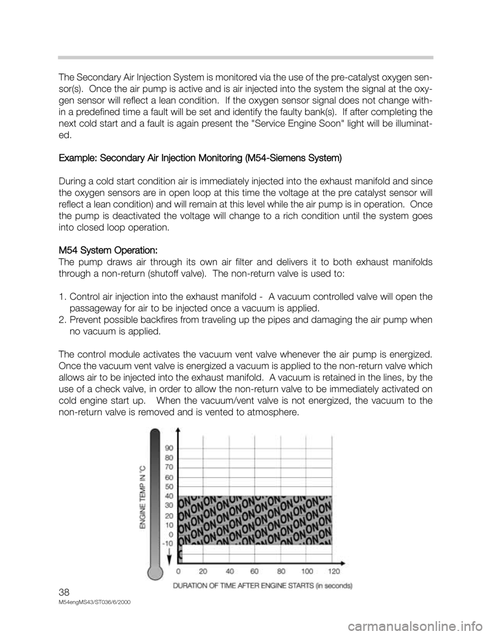
During a cold start condition air is immediately injected into the exhaust manifold and since
the oxygen sensors are in open loop at this time the voltage at the pre catalyst sensor will
reflect a lean condition) and will remain at this level while the air pump is in operation. Once
the pump is deactivated the voltage will change to a rich condition until the system goes
into closed loop operation.
M54 System Operation:
The pump draws air through its own air filter and delivers it to both exhaust manifolds
through a non-return (shutoff valve). The non-return valve is used to:
1. Control air injection into the exhaust manifold - A vacuum controlled valve will open the
passageway for air to be injected once a vacuum is applied.
2. Prevent possible backfires from traveling up the pipes and damaging the air pump when
no vacuum is applied.
The control module activates the vacuum vent valve whenever the air pump is energized.
Once the vacuum vent valve is energized a vacuum is applied to the non-return valve which
allows air to be injected into the exhaust manifold. A vacuum is retained in the lines, by the
use of a check valve, in order to allow the non-return valve to be immediately activated on
cold engine start up. When the vacuum/vent valve is not energized, the vacuum to the
non-return valve is removed and is vented to atmosphere.
Page 42 of 48

42
M54engMS43/ST036/6/2000
RESONANCE SYSTEM
The resonance system provides increased engine torque at low RPM, as well as addition-
al power at high RPM. Both of these features are obtained by using a resonance flap (in
the intake manifold) controlled by the ECM.
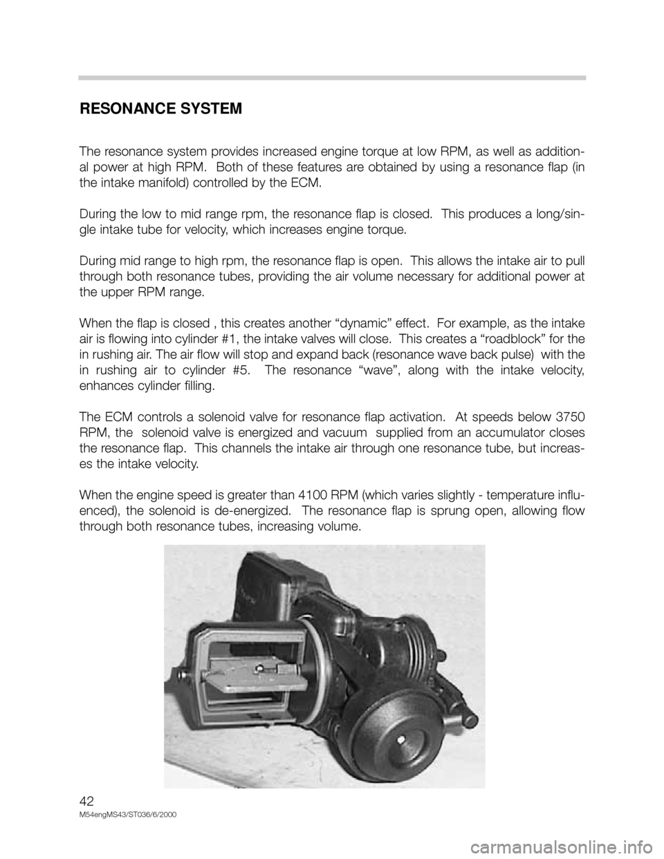
During the low to mid range rpm, the resonance flap is closed. This produces a long/sin-
gle intake tube for velocity, which increases engine torque.
During mid range to high rpm, the resonance flap is open. This allows the intake air to pull
through both resonance tubes, providing the air volume necessary for additional power at
the upper RPM range.
When the flap is closed , this creates another “dynamic” effect. For example, as the intake
air is flowing into cylinder #1, the intake valves will close. This creates a “roadblock” for the
in rushing air. The air flow will stop and expand back (resonance wave back pulse) with the
in rushing air to cylinder #5. The resonance “wave”, along with the intake velocity,
enhances cylinder filling.
The ECM controls a solenoid valve for resonance flap activation. At speeds below 3750
RPM, the solenoid valve is energized and vacuum supplied from an accumulator closes
the resonance flap. This channels the intake air through one resonance tube, but increas-
es the intake velocity.
When the engine speed is greater than 4100 RPM (which varies slightly - temperature influ-
enced), the solenoid is de-energized. The resonance flap is sprung open, allowing flow
through both resonance tubes, increasing volume.
Page 46 of 48

46
M54engMS43/ST036/6/2000
CRUISE CONTROL
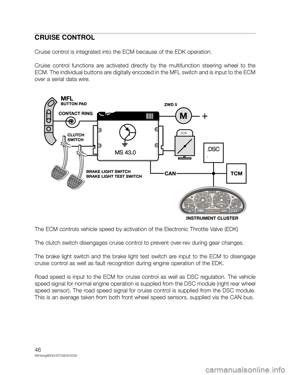
Cruise control is integrated into the ECM because of the EDK operation.
Cruise control functions are activated directly by the multifunction steering wheel to the
ECM. The individual buttons are digitally encoded in the MFL switch and is input to the ECM
over a serial data wire.
The ECM controls vehicle speed by activation of the Electronic Throttle Valve (EDK)
The clutch switch disengages cruise control to prevent over-rev during gear changes.
The brake light switch and the brake light test switch are input to the ECM to disengage
cruise control as well as fault recognition during engine operation of the EDK.
Road speed is input to the ECM for cruise control as well as DSC regulation. The vehicle
speed signal for normal engine operation is supplied from the DSC module (right rear wheel
speed sensor). The road speed signal for cruise control is supplied from the DSC module.
This is an average taken from both front wheel speed sensors, supplied via the CAN bus.
DSCMS 43.0
EDK