2005 BMW MOTORRAD K 1200 S steering
[x] Cancel search: steeringPage 4 of 165
Table of ContentsYou can also consult the in-
dex at the end of this Rider's
Manual if you want to find a
particular topic or item of in-
formation.
1 General instructions . . . 5
Overview . . . . . . . . . . . . . . . . . 6
Abbreviations and
symbols . . . . . . . . . . . . . . . . . . 6
Equipment . . . . . . . . . . . . . . . 7
Technical data . . . . . . . . . . . . 7
Currency . . . . . . . . . . . . . . . . . 7
2 General views . . . . . . . . . 9
General view, left side . . . 11
General view, right
side . . . . . . . . . . . . . . . . . . . . . 13
Underneath the seat . . . . . 14
Handlebar fitting, left . . . . . 15
Handlebar fitting, right . . . 16
Instrument cluster . . . . . . . 17
Headlight . . . . . . . . . . . . . . . 183 Status indicators . . . . . 19
Multifunction display . . . . . 20
Warning and telltale
lights . . . . . . . . . . . . . . . . . . . 20
ABS warning light . . . . . . . 20
Function indicators . . . . . . 20
Warnings, general . . . . . . . 21
ABS warning
indicators . . . . . . . . . . . . . . . 28
4 Operation . . . . . . . . . . . . . 35
Ignition switch and
steering lock . . . . . . . . . . . . 36
Electronic immobiliser . . . 37
Hazard warning
flashers . . . . . . . . . . . . . . . . . 38
Tripmaster . . . . . . . . . . . . . . 39
On-board computer
OE
... 41
Clock . . . . . . . . . . . . . . . . . . . 44
Emergency off switch (kill
switch) . . . . . . . . . . . . . . . . . . 45
Grip heating
OE
........... 45
Clutch . . . . . . . . . . . . . . . . . . 46
Brakes . . . . . . . . . . . . . . . . . . 46
Lights . . . . . . . . . . . . . . . . . . . 47
Headlight . . . . . . . . . . . . . . . 48 Turn indicators . . . . . . . . . . 49
Seat . . . . . . . . . . . . . . . . . . . . 50
Helmet holder . . . . . . . . . . . 52
Luggage loops . . . . . . . . . . 53
Mirrors . . . . . . . . . . . . . . . . . . 53
Spring preload . . . . . . . . . . 53
Shock absorbers . . . . . . . . 54
Electronic Suspension
Adjustment ESA
OE
....... 56
Tyres . . . . . . . . . . . . . . . . . . . 57
5 Riding . . . . . . . . . . . . . . . . 59
Safety instructions . . . . . . . 60
Checklist . . . . . . . . . . . . . . . . 62
Starting . . . . . . . . . . . . . . . . . 62
Pulling away . . . . . . . . . . . . . 65
Running in . . . . . . . . . . . . . . 65
Parking your
motorcycle . . . . . . . . . . . . . . 69
Refuelling . . . . . . . . . . . . . . . 76
Brake system, general . . . 77
Brake system with BMW
Integral ABS . . . . . . . . . . . . . 77
Page 37 of 165
Operation
Ignition switch and steering
lock . .......................... 36
Electronic immobiliser ......... 37
Hazard warning flashers . . . .... 38
Tripmaster .................... 39
On-board computer
OE
......... 41
Clock ......................... 44
Emergency off switch (kill
switch) ........................ 45
Grip heating
OE
................ 45
Clutch ........................ 46
Brakes ........................ 46
Lights ......................... 47
Headlight . .................... 48
Turn indicators . ............... 49
Seat . ......................... 50 Helmet holder . .
............... 52
Luggage loops . ............... 53
Mirrors . . . ..................... 53
Spring preload . ............... 53
Shock absorbers .............. 54
Electronic Suspension
Adjustment ESA
OE
............ 56
Tyres ......................... 57
435zOperation
Page 38 of 165
Ignition switch and
steering lockKeysYou receive one master key
and one spare key. Please
consult the information on the
electronic immobiliser (EWS) if
a key is lost or mislaid ( 37).Ignition switch and steer-
ing lock, tank filler cap
lock and seat lock are all op-
erated with the same key. If
you wish you can arrange to
have the cases available as
optional accessories fitted
with locks that can be opened
with this key as well.
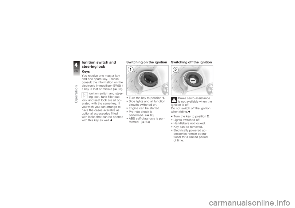
Switching on the ignitionTurn the key to position 1.
Side lights and all function
circuits switched on.
Engine can be started.
Pre-ride check is
performed. ( 63)
ABS self-diagnosis is per-
formed. ( 64)
Switching off the ignition
Brake servo assistance
is not available when the
ignition is off.
Do not switch off the ignition
when riding.
Turn the key to position 2.
Lights switched off.
Handlebars not locked.
Key can be removed.
Electrically powered ac-
cessories remain opera-
tional for a limited period
of time.
436zOperation
Page 39 of 165
The battery can be
recharged via the on-board
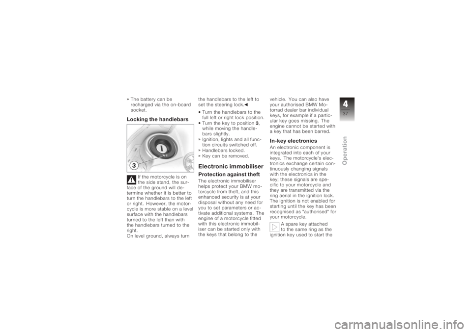
socket.Locking the handlebars
If the motorcycle is on
the side stand, the sur-
face of the ground will de-
termine whether it is better to
turn the handlebars to the left
or right. However, the motor-
cycle is more stable on a level
surface with the handlebars
turned to the left than with
the handlebars turned to the
right.
On level ground, always turn the handlebars to the left to
set the steering lock.
Turn the handlebars to the
full left or right lock position.
Turn the key to position 3,
while moving the handle-
bars slightly.
Ignition, lights and all func-
tion circuits switched off.
Handlebars locked.
Key can be removed.
Electronic immobiliserProtection against theftThe electronic immobiliser
helps protect your BMW mo-
torcycle from theft, and this
enhanced security is at your
disposal without any need for
you to set parameters or ac-
tivate additional systems. The
engine of a motorcycle fitted
with this electronic immobil-
iser can be started only with
the keys that belong to the vehicle. You can also have
your authorised BMW Mo-
torrad dealer bar individual
keys, for example if a partic-
ular key goes missing. The
engine cannot be started with
a key that has been barred.
In-key electronicsAn electronic component is
integrated into each of your
keys. The motorcycle's elec-
tronics exchange certain con-
tinuously changing signals
with the electronics in the
key; these signals are spe-
cific to your motorcycle and
they are transmitted via the
ring aerial in the ignition lock.
The ignition is not enabled for
starting until the key has been
recognised as "authorised" for
your motorcycle.
A spare key attached
to the same ring as the
ignition key used to start the
437zOperation
Page 71 of 165
Parking your motor-
cycle
Placing motorcycle on
side stand
If the ground is soft or
uneven, there is no guar-
antee that the motorcycle will
rest firmly on the stand.
Always check that the ground
under the stand is level and
firm.
Switch off the engine.
Pull the handbrake lever.
Hold the motorcycle upright
and balanced.
Use your left foot to extend
the side stand fully (arrow). The side stand is de-
signed to support only
the weight of the motorcycle.
Do not lean or sit on the mo-
torcycle with the side stand
extended. Slowly lean the motorcycle
to the side until its weight
is taken by the stand and
dismount to the left.
If the motorcycle is on
the side stand, the sur-
face of the ground will de-
termine whether it is better to
turn the handlebars to the left
or right. However, the motor-
cycle is more stable on a level
surface with the handlebars
turned to the left than with
the handlebars turned to the
right.
On level ground, always turn
the handlebars to the left to
set the steering lock.
Turn the handlebars to full
left or right lock.
Check that the motorcycle
is standing firmly. On a gradient, the mo-
torcycle should always
face uphill; select 1st gear.
569zRiding
Page 73 of 165
Removing motorcycle
from side standUnlock the steering lock.Brake servo assistance
is not available when the
ignition is off; the motorcycle
can start to roll.
Particularly when the motor-
cycle is parked on a gradi-
ent, switch on the ignition and
wait for the ABS to complete
its self-diagnosis.
Switch on the ignition.
Wait for ABS self-diagnosis
to complete.
From the left, grip the
handlebars with both hands.
Pull the handbrake lever.
Swing your right leg over
the seat and lift the motor-
cycle to the upright posi-
tion.
Hold the motorcycle upright
and balanced. An extended side stand
can catch on the ground
when the motorcycle is mov-
ing and lead to a fall.
Retract the side stand before
moving the motorcycle.
Sit on the motorcycle and
use your left foot to retract
the side stand.
571zRiding
Page 85 of 165
board power supply system is
minimised, the supply to the
power socket is cut off ap-
proximately 15 minutes after
the ignition is switched off,
and it is also temporarily in-
terrupted during the start pro-
cedure.Cable routingThe cables from the power
socket to the auxiliary device
must be routed in such a way
that they:Do not impede the rider
Do not restrict or obstruct
the steering angle and
handling characteristics
Cannot be trapped
Incorrectly routed cables
can impede the rider.
Route the cables as
described above.
683zAccessories
Page 158 of 165

LightsSwitching off the parking
lights, 48
Switching on the high-beam
headlight, 47
Switching on the low-beam
headlight, 47
Switching on the parking
lights, 48
Switching on the side
lights, 47
M
Multifunction display, 17, 20
O
On-board computer Ambient temperature, 43
Average consumption, 43
Average speed, 42
Pushbutton, 15
Resetting average con-
sumption, 43
Resetting average
speed, 42 Residual range, 42
Selecting readings, 41
Tripmaster function, 41
P
Power socket, 11, 13
Pre-ride check, 63
R
Rear wheel stand Installing, 111
Refuelling, 76
Reserve Warning, 24
Residual range, 40, 42
Restoring to use, 129
Rev. counter, 17
Running gear Technical data, 137
S
Seat Installation, 51
Lock, 11, 13
Removal, 50
Service, 144 Side stand
Starting the engine, 62
Speedometer, 17
Spring preload, rear Adjusting, 11, 13, 54
Starter, 16
Steering lock, 37
Suspension damping, rear Adjusting, 11, 13, 54
T
Technical data Brakes, 138
Bulbs, 140
Clutch, 136
Electrics, 139
Engine, 134
Engine oil, 135
Final drive, 137
Frame, 141
Fuel, 135
Running gear, 137
Transmission, 136
Wheels and tyres, 138
Telltale lights, 17
11156zIndex