Page 226 of 457
5-4
ENGINEENG
Order Job / Part Q’ty Remarks
Disassembling the exhaust valve
pipe
Washer
Pulley
Collar
Plate
Spring
Housing
Gasket
Shaft arm
Exhaust valve pipe
EXUP pulley bracket1
1
1
1
1
1
1
1
1
1Disassemble the parts in the order listed.
For assembly, reverse the disassembly
procedure.
1
2
3
4
5
6
7
8
9
10
10 Nm (1.0 m�kg, 7.2 ft�lb)
10 Nm (1.0 m�kg, 7.2 ft�lb)
7 Nm (0.7 m�kg, 5 ft�lb)
ProCarManuals.com
Page 227 of 457
5-5
Order Job / Part Q’ty Remarks
1
2Disconnecting the leads and hoses
Fuel tank
Air filter case
Throttle body assembly
Engine oil
Oil cooler
Air cut-off valve
Starter motor
Battery negative lead
Battery positive lead1
1Disconnect the parts in the order listed.
Refer to “FUEL TANK” in chapter 3.
Refer to “AIR FILTER CASE” in chapter 3.
Refer to “THROTTLE BODIES” in
chapter 7.
Drain.
Refer to “CHANGING THE ENGINE OIL”
in chapter 3.
Refer to “OIL COOLER” in chapter 6.
Refer to “AIR INDUCTION SYSTEM” in
chapter 7.
Refer to “STARTING SYSTEM” in
chapter 7.
ENGINEENG
LEADS AND HOSES
ProCarManuals.com
Page 228 of 457
5-6
Order Job / Part Q’ty Remarks
3
4
5
6
7
8
9
10Clutch cable
Ground lead
Stator coil assembly coupler
Crankshaft position sensor lead coupler
Oil level switch connector
Neutral switch connector
Speed sensor coupler
Cylinder identification sensor coupler1
2
1
1
1
1
1
1First, disconnect the negative battery
lead, and then the positive battery lead.
For connecting, reverse the disconnec-
tion procedure.
Disconnect.
Disconnect.
Disconnect.
Disconnect.
Disconnect.
Disconnect.
For installation, reverse the removal
procedure.
CAUTION:
ENGINEENG
ProCarManuals.com
Page 229 of 457
5-7
ENGINEENG
Order Job / Part Q’ty Remarks
1
2
3
4
5
6
7
8Removing the engine
Right front engine mounting bolt
Engine mount collar (inside)
Engine mount collar (outside)
Left front engine mounting bolt
Lower self locking nut
Lower engine mounting bolt
Upper self locking nut
Upper engine mounting bolt1
1
1
1
1
1
1
1Remove the parts in the order listed.
Place a suitable stand under the frame and
engine.
NOTE:
51 Nm (5.1 m�kg, 37 ft�lb)
51 Nm (5.1 m�kg, 37 ft�lb)
45 Nm (4.5 m�kg, 33 ft�lb)
7 Nm (0.7 m�kg, 5.1 ft�lb)
45 Nm (4.5 m�kg, 33 ft�lb)
ENGINE
ProCarManuals.com
Page 230 of 457
5-8
ENGINEENG
Order Job / Part Q’ty Remarks
9
10Engine mounting adjust bolt
Engine2
1 Use the pivot shaft wrench and adapter to
loosen the engine mounting adjust bolts.
For installation, reverse the removal pro-
cedure.
NOTE:
51 Nm (5.1 m�kg, 37 ft�lb)
51 Nm (5.1 m�kg, 37 ft�lb)
45 Nm (4.5 m�kg, 33 ft�lb)
7 Nm (0.7 m�kg, 5.1 ft�lb)
45 Nm (4.5 m�kg, 33 ft�lb)
ProCarManuals.com
Page 231 of 457
5-9
ENGINEENG
NOTE:
7 Nm (0.7 m�kg, 5.1 ft�lb)
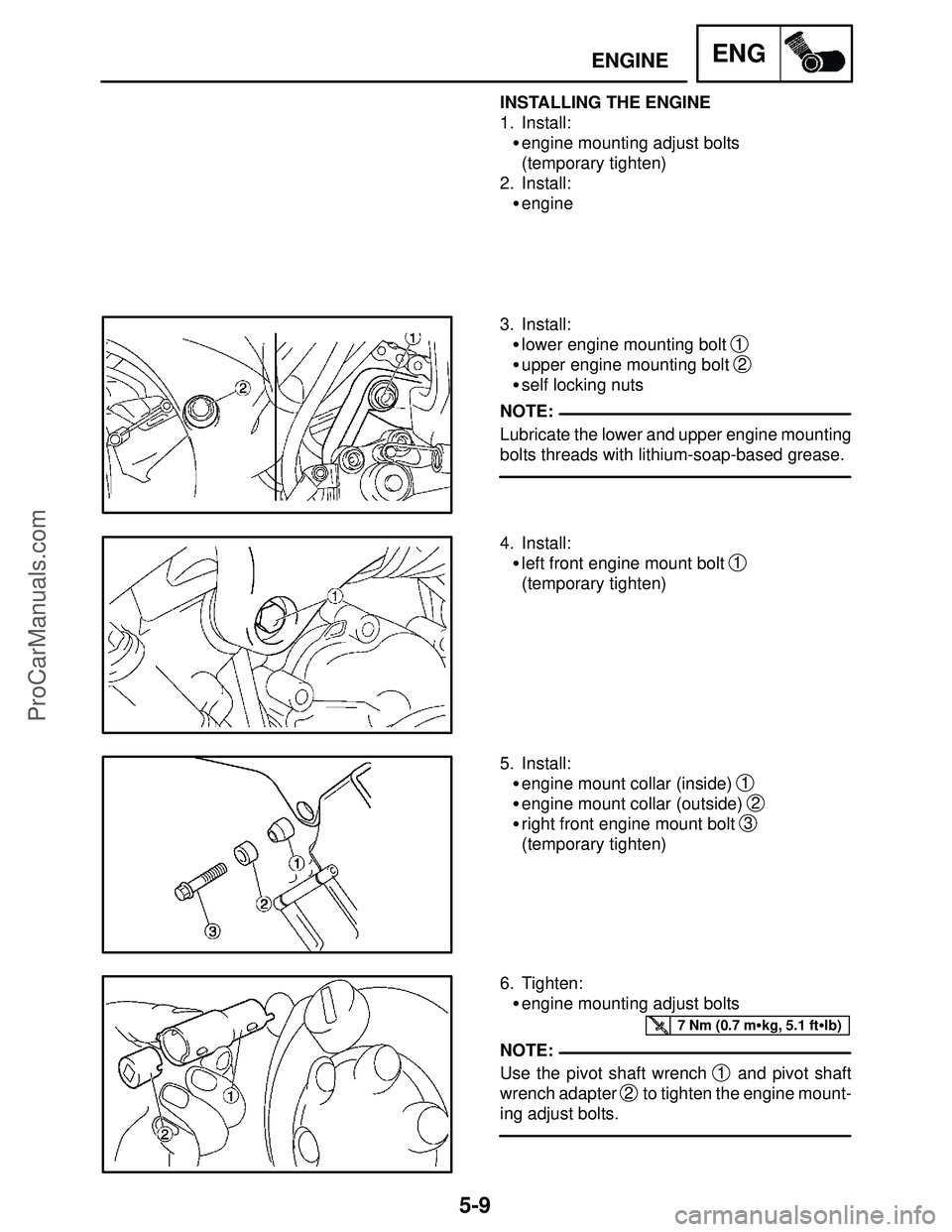
NOTE: INSTALLING THE ENGINE
1. Install:
�engine mounting adjust bolts
(temporary tighten)
2. Install:
�engine
3. Install:
�lower engine mounting bolt
1
�upper engine mounting bolt 2
�self locking nuts
Lubricate the lower and upper engine mounting
bolts threads with lithium-soap-based grease.
4. Install:
�left front engine mount bolt
1
(temporary tighten)
5. Install:
�engine mount collar (inside)
1
�engine mount collar (outside) 2
�right front engine mount bolt 3
(temporary tighten)
6. Tighten:
�engine mounting adjust bolts
Use the pivot shaft wrench
1 and pivot shaft
wrench adapter
2 to tighten the engine mount-
ing adjust bolts.
ProCarManuals.com
Page 232 of 457
5-10
ENGINEENG
51 Nm (5.1 m�kg, 37 ft�lb)
NOTE:
45 Nm (4.5 m�kg, 33 ft�lb)
45 Nm (4.5 m�kg, 33 ft�lb)
Pivot shaft wrench
90890-01471, YM-01471
Pivot shaft wrench adapter
90890-01476
7. Tighten:
�upper self-locking nut
1
�lower self-locking nut 2
First tighten the lower self-locking nut, and then
tighten the upper self-locking nut.
8. Tighten:
�left front engine mounting bolt
1
9. Tighten:
�right front engine mounting bolt
1
ProCarManuals.com
Page 240 of 457
5-18
CAMSHAFTENG
NOTE:
NOTE:
NOTE:
3. Install:
�timing chain tensioner spring
�timing chain tension rod
1
Prior to installing the timing chain tensioner rod,
drain the engine oil from the timing chain ten-
sioner housing.
a. Install the timing chain tensioner spring and
timing chain tensioner rod
1.
b. Squeeze the timing chain tensioner clip
2
and push the timing chain tensioner rod 3.
When the timing chain tensioner rod
3 is
pushed while holding the grip of the timing chain
tensioner clip
2, make sure not to release the
timing chain tensioner rod
3 before releasing
the timing chain tensioner clip
2. (Otherwise,
the timing chain tensioner rod
3 may run off.)
c. Hook the clip
4 to the timing chain tensioner
rod
3.
Hook the timing chain tensioner rod pin
5 to the
center of the clip
4. After the installation, check
that the clip
4 can come off by its own weight by
pushing the timing chain tensioner rod
3 at the
position of installation.
ProCarManuals.com


Engine mount collar (outside)
Left front engine mounting")