Page 218 of 457

4-71
SWINGARM AND DRIVE CHAINCHAS
WARNING
NOTE:
NOTE:
EAS00703
REMOVING THE SWINGARM
1. Stand the motorcycle on a level surface.
Securely support the motorcycle so that
there is no danger of it falling over.
Place the motorcycle on a suitable stand so that
the rear wheel is elevated.
2. Remove:
�relay arm-to-swingarm bolt
1
�connecting arm bolt 2
�rear shock absorber assembly lower bolt 3
When removing the rear shock absorber as-
sembly lower bolt, hold the swingarm so that it
does not drop down.
3. Measure:
�swingarm side play
�swingarm vertical movement
a. Measure the tightening torque of the pivot
shaft nut.
Pivot shaft nut
105 Nm (10.5 m�kg, 76 ft�lb)
b. Measure the swingarm side play
A by mov-
ing the swingarm from side to side.
c. If the swingarm side play is out of specifica-
tion, check the spacers, bearings, washers,
and dust covers.
Swingarm side play
(at the end of the swingarm)
1.0 mm (0.04 in)
d. Check the swingarm vertical movement
B
by moving the swingarm up and down.
If swingarm vertical movement is not smooth
or if there is binding, check the spacers,
bearings, washers, and dust covers.
ProCarManuals.com
Page 219 of 457
4-72
SWINGARM AND DRIVE CHAINCHAS
WARNING
NOTE:
NOTE:
WARNING
EAS00704
REMOVING THE DRIVE CHAIN
1. Stand the motorcycle on a level surface.
Securely support the motorcycle so that
there is no danger of it falling over.
Place the motorcycle on a suitable stand so that
the rear wheel is elevated.
2. Remove:
�drive chain
(with the drive chain cutter)
Only cut the drive chain if it or the swingarm is to
be replaced.
EAS00707
CHECKING THE SWINGARM
1. Check:
�swingarm
Bends / cracks / damage � Replace.
2. Check:
�pivot shaft
Roll the pivot shaft on a flat surface.
Bends � Replace.
Do not attempt to straighten a bent pivot
shaft.
ProCarManuals.com
Page 243 of 457
5-21
CAMSHAFTENG
10 Nm (1.0 m�kg, 7.2 ft�lb)
CAUTION:
WARNING
8. Install:
�O-ring
New
�timing chain tensioner
1
�timing chain tensioner bolts 2
The “arrow” mark a on the timing chain ten-
sioner should face up.
Always use a new O-ring.
9. Turn:
�crankshaft
(several full turns clockwise)
10. Check:
�“T” mark
a
Make sure the “T” mark on the pickup rotor is
aligned with the crankcase mating sure face
b.
�camshaft punch mark
c
Make sure the punch mark c on the cam-
shaft is aligned with the camshaft cap arrow
mark
d.
Out of alignment � Adjust.
Refer to the installation steps above.
11. Measure:
�valve clearance
Out of specification � Adjust.
Refer to “ADJUSTING THE VALVE CLEAR-
ANCE” in chapter 3.
12. Install:
�pickup coil rotor cover
Refer to “CRANKSHAFT POSITION SEN-
SOR”.
ProCarManuals.com
Page 293 of 457
5-71
OIL PAN AND OIL PUMPENG
12 Nm (1.2 m�kg, 8.7 ft�lb)
10 Nm (1.0 m�kg, 7.2 ft�lb)
43Nm (4.3 m�kg, 31 ft�lb)
WARNING
NOTE:
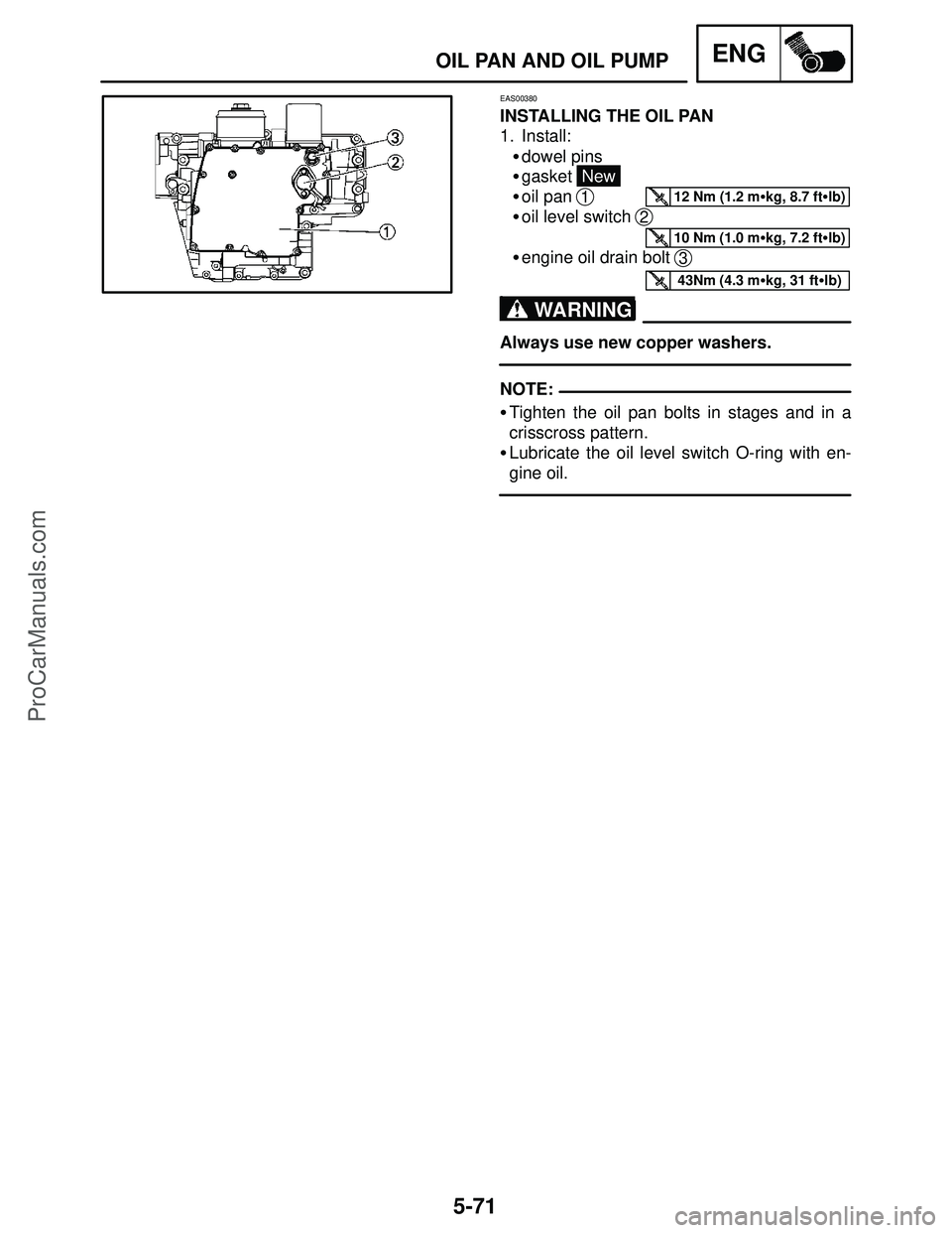
EAS00380
INSTALLING THE OIL PAN
1. Install:
�dowel pins
�gasket
New
�oil pan
1
�oil level switch 2
�engine oil drain bolt 3
Always use new copper washers.
�Tighten the oil pan bolts in stages and in a
crisscross pattern.
�Lubricate the oil level switch O-ring with en-
gine oil.
ProCarManuals.com
Page 307 of 457

5-85
CONNECTING RODS AND PISTONSENG
WARNING
CAUTION:
l. Clean the connecting rod bolts.
m. Tighten the connecting rod bolts.
n. Put a mark
1 on the corner of the connecting
rod bolt
2 and the connecting rod 3.
o. Tighten the bolt further to reach the specified
angle (150�).
p. After the installation, check that the section
shown
a is flush with each other by touching
the surface.
�Side machined face
a
�When the bolt is tightened more than the
specified angle, do not loosen the bolt and
then retighten it.
Replace the bolt with a new one and per-
form the procedure again.
�If they are not flush with each other, remove
the connecting rod bolt and big end bear-
ing and restart from step “e”. In this case,
make sure to replace the connecting rod
bolt.
�Do not use a torque wrench to tighten the
nut to the specified angle.
�Tighten the bolt until it is at the specified
angles.
q. Remove the connecting rod and big end
bearings.
Refer to “REMOVING THE CONNECTING
RODS”.
ProCarManuals.com
Page 313 of 457
5-91
CONNECTING RODS AND PISTONSENG
WARNING
CAUTION:
�When the bolt is tightened more than the
specified angle, do not loosen the bolt and
then retighten it.
Replace the bolt with a new one and per-
form the procedure again.
�If they are not flush with each other, remove
the connecting rod bolt and big end bear-
ing and restart from step “9”.
In this case, make sure to replace the con-
necting rod bolt.
�Do not use a torque wrench to tighten the
bolt to the specified angle.
�Tighten the bolt until it is at the specified
angles.
ProCarManuals.com
Page 326 of 457
5-104
TRANSMISSIONENG
WARNING
2. Check:
�shift fork guide bar
Roll the shift fork guide bar on a flat surface.
Bends � Replace.
Do not attempt to straighten a bent shift fork
guide bar.
3. Check:
�shift fork movement
(along the shift fork guide bar)
Rough movement � Replace the shift forks
and shift fork guide bar as a set.
EAS00422
CHECKING THE SHIFT DRUM ASSEMBLY
1. Check:
�shift drum grooves
1
Damage / scratches / wear � Replace the
shift drum assembly.
�shift drum segment
2
Damage / wear � Replace the shift drum as-
sembly.
�shift drum bearing
3
Damage / pitting � Replace the shift drum
assembly.
EAS00425
CHECKING THE TRANSMISSION
1. Measure:
�main axle runout
(with a centering device and dial gauge
1)
Out of specification � Replace the main
axle.
Main axle runout limit
0.08 mm (0.0032 in)
ProCarManuals.com
Page 345 of 457
7-1
FUEL INJECTION SYSTEMFI
19Atmospheric pressure
sensor
20Fuel injection system
relay
21Engine trouble warning
light
22Lean angle cut-off
switch
23Air cut-off valve
13Coolant temperature
sensor
14Spark plug
15Cylinder identification
sensor
16Pressure regulator
17Battery
18ECU
1Ignition coil
2Air filter case
3Intake temperature
sensor
4Fuel delivery hose
5Fuel tank
6Fuel pump
7Fuel return hose
8Intake air presure sen-
sor
9Throttle position sen-
sor
10Fuel injector
11Catalytic converter
12Crankshaft position
sensor
FUEL INJECTION SYSTEM
FUEL INJECTION SYSTEM
ProCarManuals.com