Page 229 of 457
5-7
ENGINEENG
Order Job / Part Q’ty Remarks
1
2
3
4
5
6
7
8Removing the engine
Right front engine mounting bolt
Engine mount collar (inside)
Engine mount collar (outside)
Left front engine mounting bolt
Lower self locking nut
Lower engine mounting bolt
Upper self locking nut
Upper engine mounting bolt1
1
1
1
1
1
1
1Remove the parts in the order listed.
Place a suitable stand under the frame and
engine.
NOTE:
51 Nm (5.1 m�kg, 37 ft�lb)
51 Nm (5.1 m�kg, 37 ft�lb)
45 Nm (4.5 m�kg, 33 ft�lb)
7 Nm (0.7 m�kg, 5.1 ft�lb)
45 Nm (4.5 m�kg, 33 ft�lb)
ENGINE
ProCarManuals.com
Page 231 of 457
5-9
ENGINEENG
NOTE:
7 Nm (0.7 m�kg, 5.1 ft�lb)
NOTE: INSTALLING THE ENGINE
1. Install:
�engine mounting adjust bolts
(temporary tighten)
2. Install:
�engine
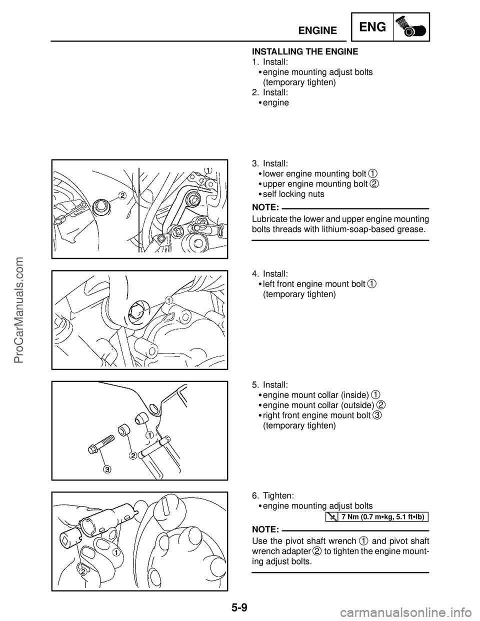
3. Install:
�lower engine mounting bolt
1
�upper engine mounting bolt 2
�self locking nuts
Lubricate the lower and upper engine mounting
bolts threads with lithium-soap-based grease.
4. Install:
�left front engine mount bolt
1
(temporary tighten)
5. Install:
�engine mount collar (inside)
1
�engine mount collar (outside) 2
�right front engine mount bolt 3
(temporary tighten)
6. Tighten:
�engine mounting adjust bolts
Use the pivot shaft wrench
1 and pivot shaft
wrench adapter
2 to tighten the engine mount-
ing adjust bolts.
ProCarManuals.com
Page 232 of 457
5-10
ENGINEENG
51 Nm (5.1 m�kg, 37 ft�lb)
NOTE:
45 Nm (4.5 m�kg, 33 ft�lb)
45 Nm (4.5 m�kg, 33 ft�lb)
Pivot shaft wrench
90890-01471, YM-01471
Pivot shaft wrench adapter
90890-01476
7. Tighten:
�upper self-locking nut
1
�lower self-locking nut 2
First tighten the lower self-locking nut, and then
tighten the upper self-locking nut.
8. Tighten:
�left front engine mounting bolt
1
9. Tighten:
�right front engine mounting bolt
1
ProCarManuals.com
Page 236 of 457
5-14
CAMSHAFTENG
NOTE:
CAUTION:
EAS00198
REMOVING THE CAMSHAFTS
1. Remove:
�pickup rotor cover
Refer to “CRANKSHAFT POSITION SEN-
SOR AND PICKUP ROTOR”.
2. Align:
�“T” mark
a on the pickup rotor
(with the crankcase mating surface
b)
a. Turn the crankshaft clockwise.
b. When piston #1 is at TDC on the compres-
sion stroke, align the “T” mark
a on the pick-
up rotor with the crankcase mating surface
b.
TDC on the compression stroke can be found
when the camshaft lobes are turned away from
each other.
3. Loosen:
�camshaft sprocket bolts
1
Camshaft wrench
90890-04143
4. Remove:
�timing chain tensioner
1
�O-ring
5. Remove:
�camshaft caps
1
�dowel pins
To prevent damage to the cylinder head,
camshafts or camshaft caps, loosen the
camshaft cap bolts in stages and in a criss-
cross pattern, working from the outside in.
ProCarManuals.com
Page 241 of 457
5-19
CAMSHAFTENG
NOTE:
NOTE:
NOTE:
EAS00215
INSTALLING THE CAMSHAFTS
1. Align:
�“T” mark
a on the pickup rotor
(with the crankcase mating surface
b)
a. Turn the crankshaft clockwise.
b. When piston #1 is at TDC, align the “T” mark
a with the crankcase mating surface b.
2. Install:
�intake camshaft sprocket
1
�exhaust camshaft sprocket 2
(with the camshaft sprockets temporarily
tightened)
Install the camshaft sprockets as a illustration.
3. Install:
�exhaust camshaft
1
�intake camshaft 2
(with the camshaft sprockets temporarily
tightened)
Make sure the punch mark
a faces up.
4. Install:
�dowel pins
�exhaust camshaft caps
�intake camshaft caps
�Make sure each camshaft cap is installed in its
original place.
�Make sure the arrow mark
a on each cam-
shaft cap points towards the right side of the
engine.
L: Left side camshaft cap mark
R: Right side camshaft cap mark
I: Intake side camshaft cap mark
E: Exhaust side camshaft cap mark
ProCarManuals.com
Page 243 of 457
5-21
CAMSHAFTENG
10 Nm (1.0 m�kg, 7.2 ft�lb)
CAUTION:
WARNING
8. Install:
�O-ring
New
�timing chain tensioner
1
�timing chain tensioner bolts 2
The “arrow” mark a on the timing chain ten-
sioner should face up.
Always use a new O-ring.
9. Turn:
�crankshaft
(several full turns clockwise)
10. Check:
�“T” mark
a
Make sure the “T” mark on the pickup rotor is
aligned with the crankcase mating sure face
b.
�camshaft punch mark
c
Make sure the punch mark c on the cam-
shaft is aligned with the camshaft cap arrow
mark
d.
Out of alignment � Adjust.
Refer to the installation steps above.
11. Measure:
�valve clearance
Out of specification � Adjust.
Refer to “ADJUSTING THE VALVE CLEAR-
ANCE” in chapter 3.
12. Install:
�pickup coil rotor cover
Refer to “CRANKSHAFT POSITION SEN-
SOR”.
ProCarManuals.com
Page 262 of 457
5-40
STARTER CLUTCH AND GENERATORENG
EAS00351
CHECKING THE STARTER CLUTCH
1. Check:
�starter clutch rollers
1
Damage / wear � Replace.
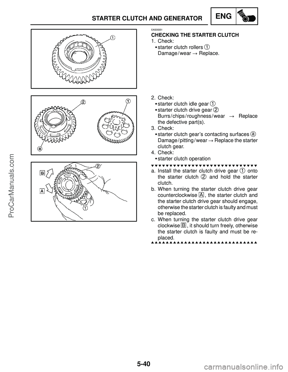
2. Check:
�starter clutch idle gear
1
�starter clutch drive gear 2
Burrs / chips / roughness / wear � Replace
the defective part(s).
3. Check:
�starter clutch gear’s contacting surfaces
a
Damage / pitting / wear � Replace the starter
clutch gear.
4. Check:
�starter clutch operation
a. Install the starter clutch drive gear
1 onto
the starter clutch
2 and hold the starter
clutch.
b. When turning the starter clutch drive gear
counterclockwise
A, the starter clutch and
the starter clutch drive gear should engage,
otherwise the starter clutch is faulty and must
be replaced.
c. When turning the starter clutch drive gear
clockwise
B, it should turn freely, otherwise
the starter clutch is faulty and must be re-
placed.
ProCarManuals.com
Page 277 of 457
5-55
CLUTCHENG
NOTE:
95 Nm(9.5 m�kg, 69 ft�lb)
NOTE:
3. Install:
�wire clip
1
4. Install:
�clutch housing
1
Align the projection of clutch housing a and
hollow of the oil pump drive gear
b.
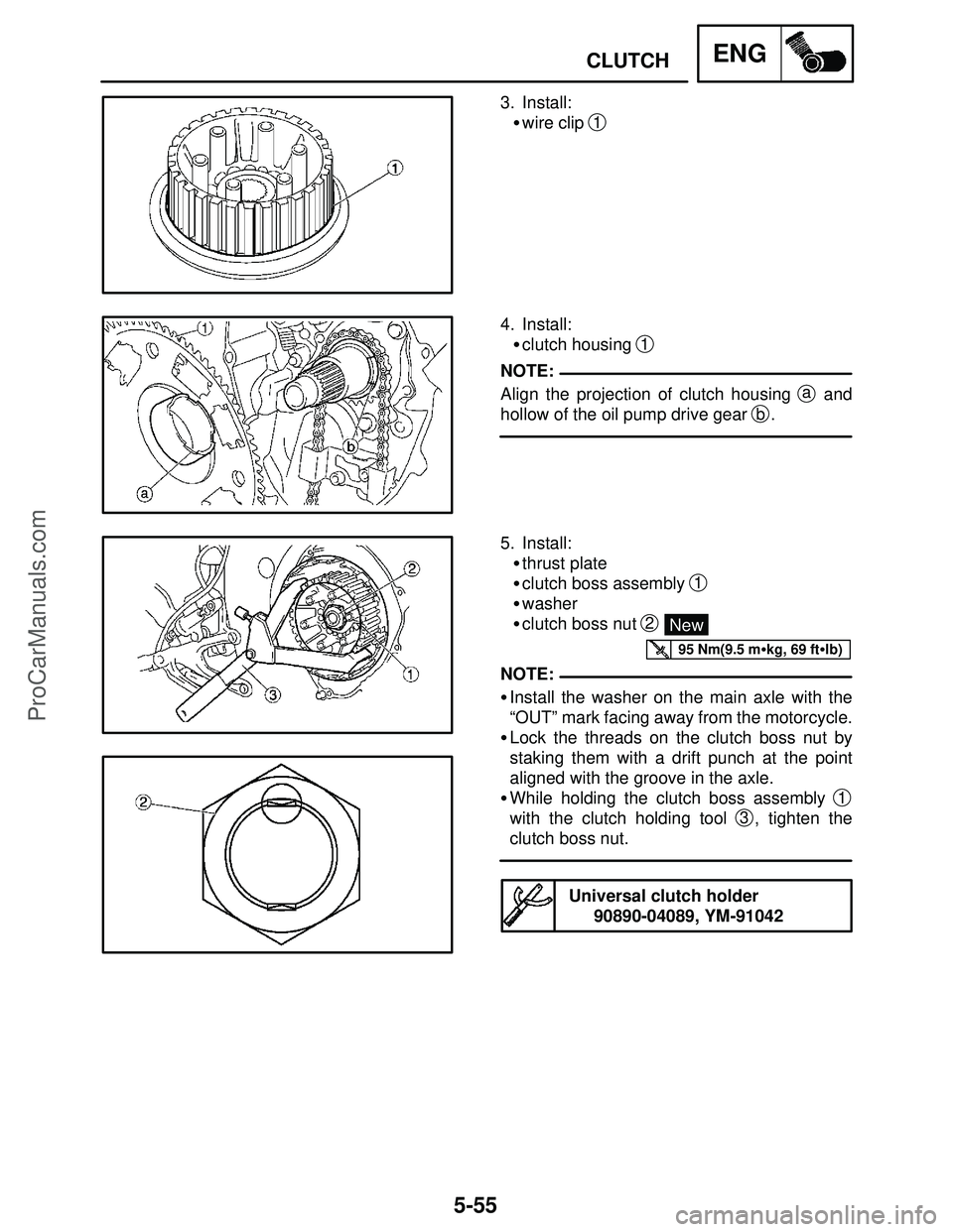
5. Install:
�thrust plate
�clutch boss assembly
1
�washer
�clutch boss nut
2 New
�Install the washer on the main axle with the
“OUT” mark facing away from the motorcycle.
�Lock the threads on the clutch boss nut by
staking them with a drift punch at the point
aligned with the groove in the axle.
�While holding the clutch boss assembly
1
with the clutch holding tool 3, tighten the
clutch boss nut.
Universal clutch holder
90890-04089, YM-91042
ProCarManuals.com

Engine mount collar (outside)
Left front engine mounting")