Page 268 of 457
5-46
Order Job / Part Q’ty Remarks
1
2
3
4
5
6Removing the clutch cover
Right side cowling
Bottom cowling
Engine oil
Cover
Clutch cable
Clutch cover
Clutch cover gasket
Dowel pin
Oil filler cap1
1
1
1
2
1Remove the parts in the order listed.
Drain.
Refer to “CHANGING THE ENGINE OIL”
in chapter 3.
Disconnect.
For installation, reverse the removal
procedure.
Refer to “COWLINGS” in chapter 3.
12 Nm (1.2 m�kg, 8.7 ft�lb)
12 Nm (1.2 m�kg, 8.7 ft�lb)
10 Nm (1.0 m�kg, 7.2 ft�lb)
CLUTCHENG
CLUTCH
CLUTCH COVER
ProCarManuals.com
Page 276 of 457
5-54
CLUTCHENG
NOTE:
EAS00286
CHECKING THE PRESSURE PLATE
1. Check:
�pressure plate
1
Cracks / damage � Replace.
�bearing
2
Damage / wear � Replace.
EAS00287
CHECKING THE PULL LEVER SHAFT AND
PULL ROD
1. Check:
�pull lever shaft pinion gear teeth
1
�pull rod teeth 2
Damage / wear � Replace the pull rod and
pull lever shaft pinion gear as a set.
2. Check:
�pull rod bearing
Damage / wear � Replace.
INSTALLING THE CLUTCH
1. Install:
�clutch damper spring seat
1
�clutch damper spring 2
2. Install:
�friction plate 3
1
�clutch plate 2 2
Lubricate the engine oil.
ProCarManuals.com
Page 278 of 457
5-56
CLUTCHENG
NOTE:
10 Nm (1.0 m�kg, 7.2 ft�lb)
NOTE:
NOTE: 6. Lubricate:
�friction plates
�clutch plates
(with the recommended lubricant)
Recommended lubricant
Engine oil
7. Install:
�friction plate 2
�clutch plate 1
1
8. Install:
�friction plate 1
1
Install the last friction plate shifting half phase.
9. Install:
�bearing
�pull rod
1
�pressure plate 2
�clutch springs
�clutch spring bolts
3
Tighten the clutch spring bolts in stages and in a
crisscross pattern.
10. Install:
�pull lever
In stall the pull lever with the “�” mark facing to-
ward upper side.
ProCarManuals.com
Page 285 of 457
5-63
Order Job / Part Q’ty Remarks
1
2
3
4
5
6
7
8Removing the oil pan and oil pump
Side cowlings
Bottom cowlings
Engine oil
Exhaust pipe and exhaust valve pipe
Clutch assembly
Water pump inlet pipe
Water pump outlet pipe
Oil level switch lead coupler
Oil level switch
Oil level switch lead holder
Oil pan
Oil pan gasket
Dowel pin
Drain pipe
Oil strainer1
1
1
1
1
2
1
1Remove the parts in the order listed.
Drain.
Refer to “CHANGING THE ENGINE OIL”
in chapter 3.
Refer to “EXHAUST PIPE”.
Refer to “CLUTCH”.
Refer to “OIL COOLER” in chapter 6.
Disconnect.
Refer to “COWLINGS” in chapter 3.
10 Nm (1.0 m�kg, 7.2 ft�lb)
10 Nm (1.0 m�kg, 7.2 ft�lb)
10 Nm (1.0 m�kg, 7.2 ft�lb)10 Nm (1.0 m�kg, 7.2 ft�lb)
12 Nm (1.2 m�kg, 8.7 ft�lb)43 Nm (4.3 m�kg, 31 ft�lb)
12 Nm (1.2 m�kg, 8.7 ft�lb)
OIL PAN AND OIL PUMPENG
EAS00356
OIL PAN AND OIL PUMP
ProCarManuals.com
Page 290 of 457
5-68
OIL PAN AND OIL PUMPENG
EAS00367
CHECKING THE OIL DELIVERY PIPE AND
OIL PIPE
1. Check:
�oil delivery pipe
1
�oil pipe 2
Damage � Replace.
Obstruction � Wash and blow out with com-
pressed air.
EAS00368
CHECKING THE OIL STRAINER
1. Check:
�oil strainer
1
Damage � Replace.
Contaminants � Clean with solvent.
EAS00373
CHECKING THE OIL NOZZLES
The following procedure applies to all of the oil
nozzles.
1. Check:
�oil nozzle
1
Damage / wear � Replace the oil nozzle.
�O-ring
2
Damage / wear � Replace.
�oil nozzle passage
Obstruction � Blow out with compressed air.
EAS00374
ASSEMBLING THE OIL PUMP
1. Lubricate:
�inner rotor
�outer rotor
�oil pump shaft
(with the recommended lubricant)
Recommended lubricant
Engine oil
ProCarManuals.com
Page 293 of 457
5-71
OIL PAN AND OIL PUMPENG
12 Nm (1.2 m�kg, 8.7 ft�lb)
10 Nm (1.0 m�kg, 7.2 ft�lb)
43Nm (4.3 m�kg, 31 ft�lb)
WARNING
NOTE:
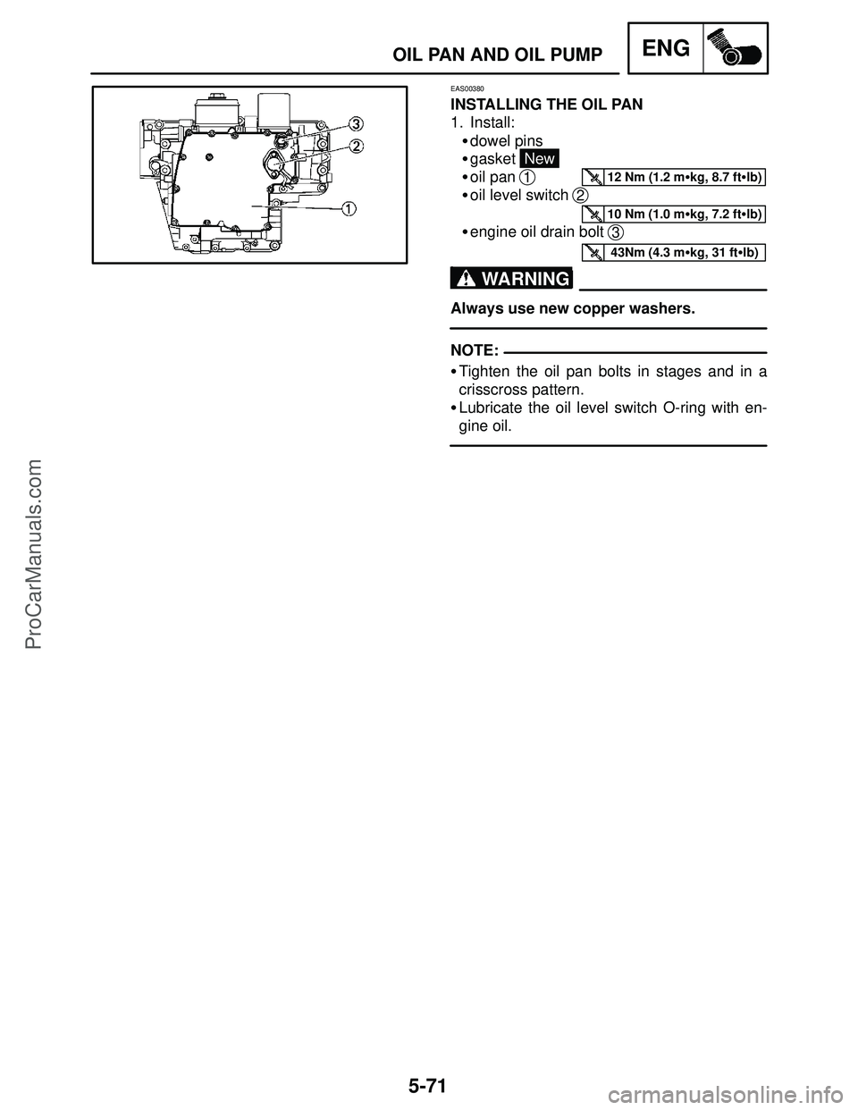
EAS00380
INSTALLING THE OIL PAN
1. Install:
�dowel pins
�gasket
New
�oil pan
1
�oil level switch 2
�engine oil drain bolt 3
Always use new copper washers.
�Tighten the oil pan bolts in stages and in a
crisscross pattern.
�Lubricate the oil level switch O-ring with en-
gine oil.
ProCarManuals.com
Page 294 of 457
5-72
Order Job / Part Q’ty Remarks
Removing the crankcase
Air filter case
Throttle body assembly
Engine
Cylinder head
Starter clutch and generator
Shift shaft
Crankshaft position sensor
Clutch
Oil pan and oil pump
Starter motorRemove the parts in the order listed.
Refer to “AIR FILTER CASE” in chapter 3.
Refer to “THROTTLE BODIES” in
chapter 7.
Refer to “ENGINE”.
Refer to “CYLINDER HEAD”.
Refer to “STARTER CLUTCH AND
GENERATOR”.
Refer to “SHIFT SHAFT”.
Refer to “CRANKSHAFT POSITION
SENSOR”.
Refer to “CLUTCH”.
Refer to “OIL PAN AND OIL PUMP”.
Refer to “STARTING SYSTEM” in
chapter 8.
12 Nm (1.2 m�kg, 8.7 ft�lb)12 Nm (1.2 m�kg, 8.7 ft�lb)
24 Nm (2.4 m�kg, 17 ft�lb)
10 Nm (1.0 m�kg, 7.2 ft�lb)
24 Nm (2.4 m�kg, 17 ft�lb)
12 Nm (1.2 m�kg, 8.7 ft�lb)
20 Nm (2.0 m�kg, 14 ft�lb) +60�
CRANKCASEENG
CRANKCASE
ProCarManuals.com
Page 297 of 457
5-75
CRANKCASEENG
NOTE:
EAS00399
CHECKING THE CRANKCASE
1. Thoroughly wash the crankcase halves in a
mild solvent.
2. Thoroughly clean all the gasket surfaces and
crankcase mating surfaces.
3. Check:
�crankcase
Cracks / damage � Replace.
�oil delivery passages
Obstruction � Blow out with compressed air.
EAS00401
CHECKING THE BEARINGS AND OIL
SEALS
1. Check:
�bearings
Clean and lubricate the bearings, then rotate
the inner race with your finger.
Rough movement � Replace.
2. Check:
�oil seals
Damage / wear � Replace.
ASSEMBLING THE CRANKCASE
1. Lubricate:
�crankshaft journal bearings
(with the recommended lubricant)
Recommended lubricant
Engine oil
2. Apply:
�sealant
Yamaha bond No. 1215
90890-85505, ACC-1109-05-01
Do not allow any sealant to come into contact
with the oil gallery or crankshaft journal bear-
ings. Do not apply sealant to within 2 � 3 mm
(0.08 � 0.12 in) of the crankshaft journal bear-
ings.
ProCarManuals.com