Page 401 of 457
8-8
IGNITION SYSTEMELEC
EAS00735
IGNITION SYSTEM
CIRCUIT DIAGRAM
ProCarManuals.com
Page 406 of 457

8-13
IGNITION SYSTEMELEC
12. Starting circuit cut-off relay (diode)
�Disconnect the starting circuit cut-off relay
coupler from the wire harness.
�Connect the pocket tester (Ω � 1) to the
starting circuit cut-off relay coupler as
shown.
�Check the starting circuit cut-off relay for
continuity.
Positive tester probe �
blue / yellow
Negative tester probe �
sky blue
1
2
EAS00753
Positive tester probe �
blue / yellow
Negative tester probe �
blue / black Continuity
1
3
Positive tester probe �
sky blue
Negative tester probe �
blue / yellow
2
1
Positive tester probe �
blue / black
Negative tester probe �
blue / yellow No
continuity
3
1
YESNO
Replace the starting
circuit cut-off relay. When you switch the positive and negative
tester probes, the readings in the above chart
will be reversed.
�Are the tester readings correct?
NOTE:
13. Lean angle cut-off switch
�Check the lean angle cut-off switch.
Refer to “FUEL INJECTION SYSTEM” in
chapter 7.
�Is the lean angle cut-off switch OK?
YESNO
Replace the lean
angle cut-off switch.
EAS00754
14. Wiring
�Check the entire ignition system’s wiring.
Refer to “CIRCUIT DIAGRAM”.
�Is the ignition system’s wiring properly con-
nected and without defects?
YESNO
Properly connect or
repair the ignition
system’s wiring.
Replace the ECU.
ProCarManuals.com
Page 407 of 457
8-14
1Main switch
4Fuse (main)
6Battery
8Starter relay
9Starter motor
10Starting circuit cut-off relay
11Neutral switch
12Sidestand switch
53Engine stop switch
54Start switch
73Fuse (ignition)
ELECTRIC STARTING SYSTEMELEC
EAS00755
ELECTRIC STARTING SYSTEM
CIRCUIT DIAGRAM
ProCarManuals.com
Page 411 of 457
8-18
�Check the entire starting system’s wiring.
Refer to “CIRCUIT DIAGRAM”.
�Is the starting system’s wiring properly con-
nected and without defects?
EAS00766
12. Wiring
YESNO
Properly connect or
repair the starting
system’s wiring.
The starting system
circuit is OK.
11. Start switch
�Check the start switch for continuity.
Refer to “CHECKING THE SWITCHES”.
�Is the start switch OK?
YESNO
Replace the right
handlebar switch.
EAS00764
10. Clutch switch
�Check the clutch switch for continuity.
Refer to “CHECKING THE SWITCHES”.
�Is the clutch switch OK?
YESNO
Replace the clutch
switch.
EAS00763EAS00752
9. Sidestand switch
�Check the sidestand switch for continuity.
Refer to “CHECKING THE SWITCHES”.
�Is the sidestand switch OK?
YESNO
Replace the side-
stand switch.
ELECTRIC STARTING SYSTEMELEC
ProCarManuals.com
Page 417 of 457
8-24
2A.C. magneto
3Rectifier / regulator
4Fuse (main)
6Battery
CHARGING SYSTEMELEC
EAS00773
CHARGING SYSTEM
CIRCUIT DIAGRAM
ProCarManuals.com
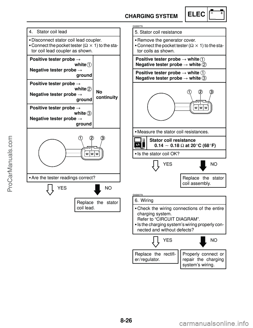
Page 419 of 457

8-26
CHARGING SYSTEMELEC
YESNO 5. Stator coil resistance
�Remove the generator cover.
�Connect the pocket tester (Ω � 1) to the sta-
tor coils as shown.
Replace the stator
coil assembly.
EAS00776
Positive tester probe � white
Negative tester probe � white
Positive tester probe � white
Negative tester probe � white1
1
2
3
�Measure the stator coil resistances.
Stator coil resistance
0.14 � 0.18 Ω at 20�C (68�F)
�Is the stator coil OK?
YESNO 6. Wiring
�Check the wiring connections of the entire
charging system.
Refer to “CIRCUIT DIAGRAM”.
�Is the charging system’s wiring properly con-
nected and without defects?
Properly connect or
repair the charging
system’s wiring.
EAS00779
Replace the rectifi-
er / regulator.
4. Stator coil lead
�Disconnect stator coil lead coupler.
�Connect the pocket tester (Ω � 1) to the sta-
tor coil lead coupler as shown.
Positive tester probe �
white
Negative tester probe �
ground
3
Positive tester probe �
white
Negative tester probe �
ground
1
Positive tester probe �
white
Negative tester probe �
groundNo
continuity
2
YESNO
Replace the stator
coil lead. �Are the tester readings correct?
ProCarManuals.com
Page 420 of 457
8-27
LIGHTING SYSTEMELEC
EAS00780
LIGHTING SYSTEM
CIRCUIT DIAGRAM
ProCarManuals.com
Page 423 of 457

8-30
�Does the Headlight relay (dimmer) have
continuity between red / yellow and
black / green ?
NOYES
Replace the dimmer
relay. Positive tester probe � red / yellow
Negative tester probe � black / green
1
2
3
4
5. Headlight relay (on / off)
�Disconnect the headlight relay (on / off) from
the coupler.
�Connect the pocket tester (Ω � 1) and bat-
tery (12 V) to the headlight relay (on / off) as
shown.
Positive battery lead � red / yellow
Negative battery lead � yellow / black
EAS00787
YESNO 7. Wiring
�Check the entire lighting system’s wiring.
Refer to “CIRCUIT DIAGRAM”.
�Is the lighting system’s wiring properly con-
nected and without defects?
Properly connect or
repair the lighting
system’s wiring.
Check the condition
of each of the lighting
system’s circuits.
Refer to “CHECK-
ING THE LIGHTING
SYSTEM”.
�Does the headlight relay (dimmer) have
continuity between black / green and
black / yellow ?
Positive tester probe � black / green
Negative tester probe � black / yellow
1
2
3
4
6. Headlight relay (dimmer)
�Disconnect the headlight relay (dimmer)
from the coupler.
�Connect the pocket tester (Ω � 1) and bat-
tery (12 V) to the headlight relay (dimmer) as
shown.
Positive battery lead � black
Negative battery lead � yellow
3
4
3
4
YESNO
Replace the head-
light relay (dimmer).
LIGHTING SYSTEMELEC
ProCarManuals.com