Page 160 of 506
3 - 20
INSP
ADJ
REAR BRAKE PAD INSPECTION AND REPLACEMENT
REAR BRAKE PAD INSPECTION AND
REPLACEMENT
1. Inspect:
�Brake pad thickness a
Out of limit → Replace as a set.
Brake pad thickness:
3.7 mm (0.15 in)
: 1.0 mm (0.04 in)
5PA30410
2. Replace:
�Brake pad
Brake pad replacement steps:
�Loosen the pad pins 1 and remove the
brake caliper 2.
NOTE:
Before removing the brake caliper from the
swingarm, loosen the pad pins.
�Remove the pad pins 3 and brake pads
4.
�Connect the transparent hose 5 to the
bleed screw 6 and place the suitable con-
tainer under its end.
�Loosen the bleed screw and push the
brake caliper piston in.
CAUTION:
Do not reuse the drained brake fluid.
�Tighten the bleed screw.
T R..
Bleed screw:
6 Nm (0.6 m kg, 4.3 ft lb)
�Install the brake pads 7 and pad pins 8.
NOTE:
Install the brake pad fitted with the brake
pad shim 9 on the brake caliper piston side.
5PA30420
5PA30430
5PA30440
5PA30450
Page 168 of 506

3 - 24
INSP
ADJDRIVE CHAIN SUPPORT INSPECTION/
FRONT FORK INSPECTION
3. Adjust:
�Drive chain slack
DRIVE CHAIN SUPPORT INSPECTION
1. Inspect:
�Drive chain support wear limit
Limit reaches indicator a → Replace.
Refer to “SWINGARM” section in the
CHAPTER 5. Drive chain slack adjustment steps:
�Loosen the axle nut 1 and locknuts 2.
�Adjust chain slack by turning the adjusters 3.
To tighten
→ Turn adjuster
3 clockwise.
To loosen
→ Turn adjuster
3 counter-
clockwise and push wheel forward.
�Turn each adjuster exactly the same
amount to maintain correct axle alignment.
(There are marks a on each side of chain
puller alignment.)
NOTE:
Turn the adjuster so that the chain is in line
with the sprocket, as viewed from the rear.
CAUTION:
Too small chain slack will overload the
engine and other vital parts; keep the
slack within the specified limits.
�Tighten the axle nut while pushing down
the drive chain.
T R..
Axle nut:
90 Nm (9.0 m kg, 65 ft lb)
�Tighten the locknuts.
T R..
Locknut:
16 Nm (1.6 m kg, 11 ft lb)
5PAR0004
5PAR0005
a a
EC36C000
FRONT FORK INSPECTION
1. Inspect:
�Front fork smooth action
Operate the front brake and stroke the front
fork.
Unsmooth action/oil leakage → Repair or
replace.
5PA30570
Page 174 of 506
3 - 27
INSP
ADJ
REAR SHOCK ABSORBER INSPECTION
�STANDARD POSITION:
This is the position which is back by the spe-
cific number of clicks from the fully turned-in
position.
CAUTION:
Do not force the adjuster past the minimum
or maximum extent of adjustment. The
adjuster may be damaged.
WARNING
Always adjust each front fork to the same
setting. Uneven adjustment can cause poor
handling and loss of stability.
3. Install:
�Rubber cap
Extent of adjustment
Maximum Minimum
Fully turned in
position20 clicks out (from
maximum position)
Standard position:
YZ85: 10 clicks out
YZ85LW: 9 clicks out
EC36K000
REAR SHOCK ABSORBER INSPECTION
1. Inspect:
�Swingarm smooth action
Abnormal noise/unsmooth action →
Grease the pivoting points or repair the piv-
oting points.
Damage/oil leakage → Replace.
5PA30620
Page 298 of 506
4 - 51
ENG
EC4M3000
REMOVAL POINTS
EC4F3100
Drive sprocket
1. Remove:
�Nut (drive sprocket) 1
�Lock washer 2
NOTE:
�Straighten the lock washer tab.
�Loosen the nut while applying the rear brake.5PA41510
2. Remove:
�Drive sprocket 1
�Drive chain 2
NOTE:
Remove the drive sprocket together with the
drive chain.
5PA41520
EC4M3301
Engine removal
1. Remove:
�Pivot shaft 1
NOTE:
If the pivot shaft is pulled all the way out, the
swingarm will come loose. If possible, insert a
shaft of similar diameter into the other side of
the swingarm to support it.5PA41530
2. Remove:
�Engine 1
From right side.
NOTE:
Make sure that the couplers, hoses and cables
are disconnected.
5PA41540
ENGINE REMOVAL
Page 426 of 506
5 - 51
CHASSWINGARM
EC570000
SWINGARM
5PAR0019
Extent of removal:
1 Swingarm removal
Extent of removal Order Part name Q’ty Remarks
SWINGARM REMOVAL
WARNING
Support the machine securely so there is no
danger of it falling over.
Preparation for removal Hold the machine by placing the
suitable stand under the engine.
Real wheel Refer to “FRONT WHEEL AND REAR
WHEEL” section.
Brake hose holder
Rear brake caliper
Drive chainRefer to “FRONT BRAKE AND REAR
BRAKE” section.
1 Drive chain support 1
2 Bolt (connecting rod) 1 Hold the swingarm.
3 Bolt (rear shock absorber-relay
arm)1
4 Pivot shaft 1
5 Swingarm 1
1
Page 428 of 506
5 - 52
CHAS
EC578000
SWINGARM DISASSEMBLY
5PAR0020
Extent of removal:
1 Swingarm disassembly
2 Connecting rod removal and disassembly
3 Relay arm removal and disassembly
Extent of removal Order Part name Q’ty Remarks
SWINGARM DISASSEMBLY
1 Relay arm 1
2 Connecting rod 1
3 Cover 2
4 Dust seal 2
5 Collar 5
6 Bushing 4
7 Oil seal 8
8 Bearing 9
Refer to “REMOVAL POINTS”.
9 Bushing (swingarm)
2
1
2
2
3
3
SWINGARM
Page 430 of 506
5 - 53
CHAS
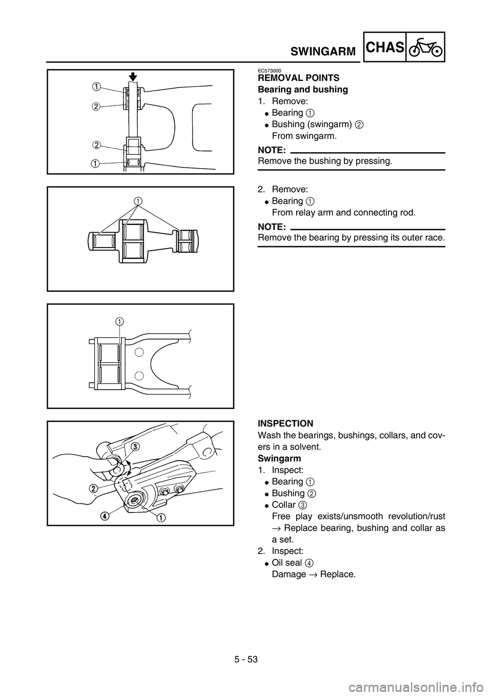
EC573000
REMOVAL POINTS
Bearing and bushing
1. Remove:
�Bearing 1
�Bushing (swingarm) 2
From swingarm.
NOTE:
Remove the bushing by pressing.5PA51640
2. Remove:
�Bearing 1
From relay arm and connecting rod.
NOTE:
Remove the bearing by pressing its outer race.
5PAR0021
1
5PAR0022
INSPECTION
Wash the bearings, bushings, collars, and cov-
ers in a solvent.
Swingarm
1. Inspect:
�Bearing 1
�Bushing 2
�Collar 3
Free play exists/unsmooth revolution/rust
→ Replace bearing, bushing and collar as
a set.
2. Inspect:
�Oil seal 4
Damage → Replace.
5PA51680
SWINGARM
Page 432 of 506
 2
�Bushing 3
Free play exists/unsmooth revolution/rust
→ Replace bearing and bushing as a set.
2. Inspect:
�Bearing (polylu")
5 - 54
CHAS
Relay arm
1. Inspect:
�Bearing 1
�Bearing (polylube bearing) 2
�Bushing 3
Free play exists/unsmooth revolution/rust
→ Replace bearing and bushing as a set.
2. Inspect:
�Bearing (polylube bearing) 2
Loss of solid lubrication → Replace.
�Oil seal 4
Damage → Replace.
NOTE:
Polylube bearings, with solid lubrication, have
been adopted with the intent to make the nee-
dle bearings, used in this model, maintenance
free. With polylube bearings, no grease nipple
and regular lubrication is necessary. However,
grease should be applied to all oil seals and
collars when removed or installed.
Connecting rod
1. Inspect:
�Bearing 1
�Bushing 2
Free play exists/unsmooth revolution/rust
→ Replace bearing and bushing as a set.
2. Inspect:
�Oil seal 3
Damage → Replace.
5PAR0023
5PA51700
EC575000
ASSEMBLY AND INSTALLATION
Bearing, bushing and oil seal
1. Install:
�Bearing 1
�Bushing (swingarm) 2
�Oil seal 3
To swingarm.
NOTE:
�Apply the molybdenum disulfide grease on
the bearing and bushing when installing.
�Install the bearing by pressing it on the side
having the manufacture’s marks or numbers.
�First install the bushing and then the bearing
to a specified depth from inside.
Installed depth of bearings and
bushings:
Bearing a: 4.5 mm (0.18 in)
Bushing b: 4.5 mm (0.18 in)
5PA51730
5PA51740
SWINGARM