Page 242 of 506
4 - 23
ENG
NOTE:
When you purchase a cylinder, you cannot
designate its size. Choose the piston that
matches the above chart.
ASSEMBLY AND INSTALLATION
Piston ring and piston
1. Install:
�Piston ring 1
NOTE:
�Take care not to scratch the piston or dam-
age the piston ring.
�Align the piston ring gap with the pin 2.
�After installing the piston ring, check the
smooth movement of it.
5PA40620
2. Install:
�Gasket (cylinder) 1
�Small end bearing 2
�Dowel pin 3
NOTE:
�Apply the engine oil on the bearing (crank-
shaft and connecting rod) and connecting
rod big end washers.
�Install the gasket with the seal print side
toward the crankcase.
5PA40630
CYLINDER HEAD, CYLINDER AND PISTON
Page 244 of 506
4 - 24
ENG
3. Install:
�Piston 1
�Piston pin 2
�Piston pin clip 3
NOTE:
�The arrow a on the piston dome must point
to exhaust side.
�Before installing the piston pin clip, cover the
crankcase with a clean rag to prevent the
piston pin clip from falling into the crankcase
cavity.
CAUTION:
Do not allow the clip open ends to meet the
piston pin slot b.
5PA40640
5PA40650
Cylinder head and cylinder
1. Apply:
�Engine oil
To piston 1, piston ring 2 and cylinder
surface.
2. Install:
�Cylinder 1
CAUTION:
Make sure the piston ring is properly posi-
tioned. Install the cylinder with one hand
while compressing the piston ring with the
other hand.
NOTE:
After installing, check the smooth movement of
the piston.
5PA40660
5PA40670
3. Install:
�Nut (cylinder) 1
NOTE:
Tighten the nuts in stage, using a crisscross
pattern.
5PA40680
T R..28 Nm (2.8 m · kg, 20 ft · lb)
CYLINDER HEAD, CYLINDER AND PISTON
Page 248 of 506
4 - 26
ENGCLUTCH AND PRIMARY DRIVEN GEAR
EC490000
CLUTCH AND PRIMARY DRIVEN GEAR
EC498000
CLUTCH PLATE AND FRICTION PLATE
5PA40720
Extent of removal:
1 Clutch plate and friction plate removal
Extent of removal Order Part name Q’ty Remarks
CLUTCH PLATE AND FRIC-
TION PLATE REMOVAL
Preparation for removal Drain the transmission oil. Refer to “TRANSMISSION OIL
REPLACEMENT” section in the CHAP-
TER 3.
Clutch cable Disconnect at engine side.
1 Clutch cover 1
2 Bolt (clutch spring) 5
3 Clutch spring 5
4 Pressure plate 1
5 Friction plate 7
6 Clutch plate 6
1
Page 272 of 506
4 - 38
ENG
2. Install:
�Spring guide 1
NOTE:
Slide the spring guide into the kick shaft, make
sure the groove a in the spring guide fits on
the stopper of the torsion spring.
5PA41120
3. Install:
�Kick shaft assembly 1
NOTE:
�Apply the transmission oil on the kick shaft.
�Apply the lithium soap base grease on the
kick shaft stopper.
�Slide the kick shaft assembly into the crank-
case, make sure the clip 2 and kick shaft
stopper a fit into their home positions b, c.5PA41130
4. Hook:
�Torsion spring 1
NOTE:
Turn the torsion spring clockwise and hook
into the proper hole a in the crankcase.
5PA41140
Kick idle gear
1. Install:
�Washer 1
�Kick idle gear 2
�Circlip 3
NOTE:
�Apply the transmission oil on the kick idle
gear inner circumference.
�Install the kick idle gear with its groove a
facing the engine.
5PA41150
KICK SHAFT, SHIFT SHAFT AND PRIMARY DRIVE GEAR
Page 276 of 506
4 - 40
ENG
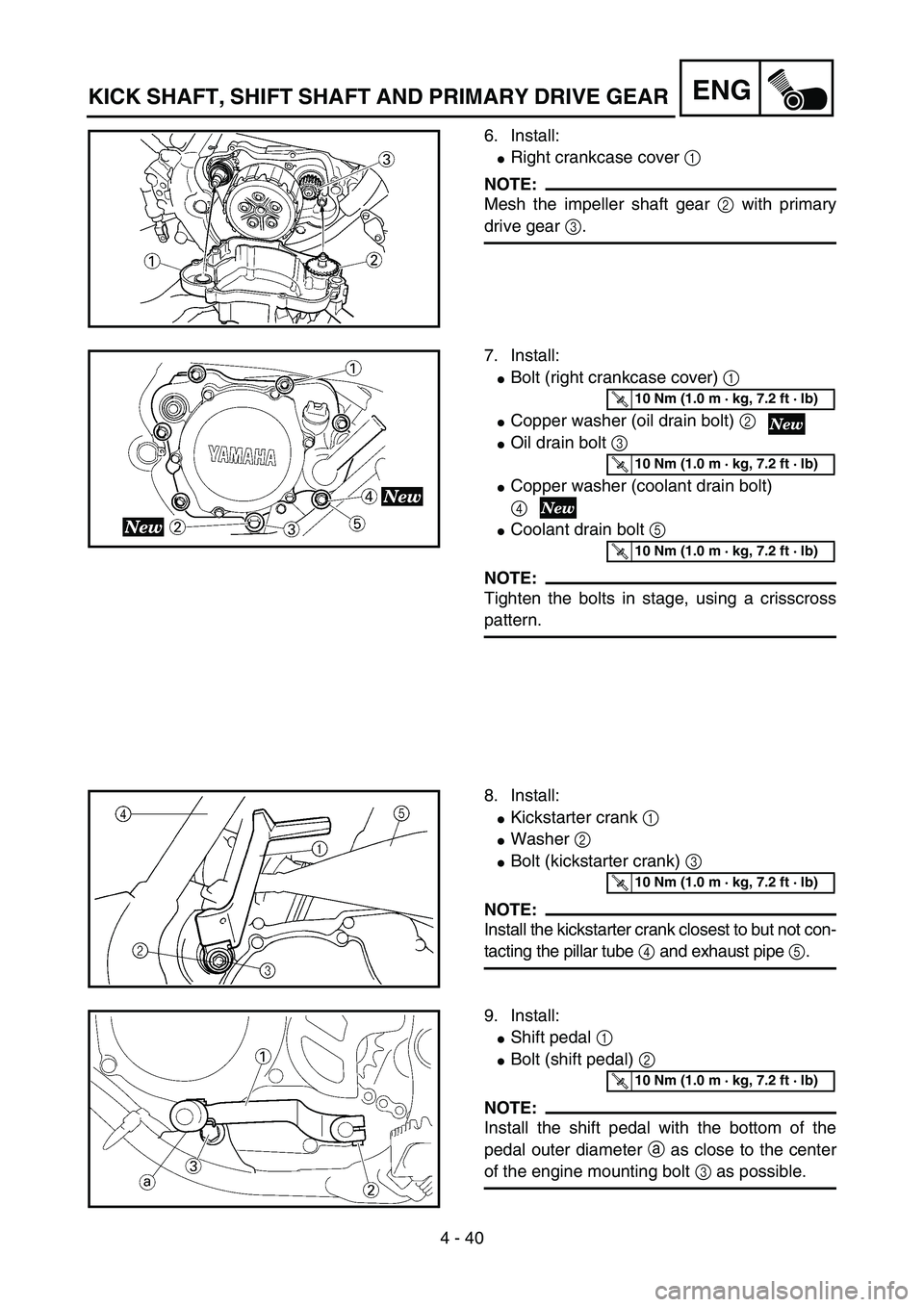
6. Install:
�Right crankcase cover 1
NOTE:
Mesh the impeller shaft gear 2 with primary
drive gear 3.
5PA41200
7. Install:
�Bolt (right crankcase cover) 1
�Copper washer (oil drain bolt) 2
�Oil drain bolt 3
�Copper washer (coolant drain bolt)
4
�Coolant drain bolt 5
NOTE:
Tighten the bolts in stage, using a crisscross
pattern.
5PA41210
T R..10 Nm (1.0 m · kg, 7.2 ft · lb)
T R..10 Nm (1.0 m · kg, 7.2 ft · lb)
T R..10 Nm (1.0 m · kg, 7.2 ft · lb)
8. Install:
�Kickstarter crank 1
�Washer 2
�Bolt (kickstarter crank) 3
NOTE:
Install the kickstarter crank closest to but not con-
tacting the pillar tube 4 and exhaust pipe 5.
5PA41220
T R..10 Nm (1.0 m · kg, 7.2 ft · lb)
9. Install:
�Shift pedal 1
�Bolt (shift pedal) 2
NOTE:
Install the shift pedal with the bottom of the
pedal outer diameter a as close to the center
of the engine mounting bolt 3 as possible.
5PA41230
T R..10 Nm (1.0 m · kg, 7.2 ft · lb)
KICK SHAFT, SHIFT SHAFT AND PRIMARY DRIVE GEAR
Page 302 of 506
4 - 53
ENG
CRANKCASE AND CRANKSHAFT
5PAR0009
Extent of removal:
1 Crankcase separation
2 Crankshaft removal
3 Crankshaft bearing removal
Extent of removal Order Part name Q’ty Remarks
CRANKCASE AND CRANK-
SHAFT REMOVAL
Preparation for removal Engine Refer to “ENGINE REMOVAL” section.
Piston Refer to “CYLINDER HEAD, CYLINDER
AND PISTON” section.
Primary drive gear
Refer to “KICK SHAFT, SHIFT SHAFT
AND PRIMARY DRIVE GEAR” section. Kick idle gear
Stopper lever assembly
Rotor and stator Refer to “CDI MAGNETO” section.
1 Screw (crankcase) 11
2 Crankcase oil seal holder 1
3 Right crankcase 1
Use special tool.
Refer to “REMOVAL POINTS”.
4 Left crankcase 1
5 Crankshaft 1 Use special tool.
Refer to “REMOVAL POINTS”.
6 Oil seal 2
7 Bearing 2 Refer to “REMOVAL POINTS”.
2
1
3
CRANKCASE AND CRANKSHAFT
Page 306 of 506
4 - 55
ENG
EC4N3401
Crankshaft bearing
1. Remove:
�Bearing 1
NOTE:
�Remove the bearing from the crankcase by
pressing its inner race as shown in È.
�If the bearing is removed together with the
crankshaft, remove the bearing using a gen-
eral bearing puller 2 as shown in É.
�Do not use the removed bearing.
5PA41630
EC4N4000
INSPECTION
Crankcase
1. Inspect:
�Contacting surface a
Scratches → Replace.
�Engine mounting boss b, crankcase
Cracks/damage → Replace.
5PA41650
2. Inspect:
�Bearing 1
Rotate inner race with a finger.
Rough spot/seizure → Replace.
5PA41660
3. Inspect:
�Oil seal 1
Damage → Replace.
5PA41670
È
É
CRANKCASE AND CRANKSHAFT
Page 312 of 506
4 - 58
ENG
4. Install:
�Dowel pin 1
�Right crankcase 2
To left crankcase 3.
NOTE:
�Turn the shift cam 4 to the position shown in
the figure so that it does not contact the
crankcase when installing the crankcase.
�Fit the right crankcase onto the left crank-
case. Tap lightly on the case with soft ham-
mer.
�When installing the crankcase, the connect-
ing rod should be positioned at TDC (top
dead center).
5PA41760
5PA41770
5. Install:
�Clamp 1
�Screw (crankcase) 2
NOTE:
Tighten the crankcase tightening screws in
stage, using a crisscross pattern.
5PA41780
T R..8 Nm (0.8 m · kg, 5.8 ft · lb)
6. Install:
�Crankcase oil seal holder 1
�Bolt (crankcase oil seal holder) 2
7. Remove:
�Sealant
Forced out on the cylinder mating surface.
8. Apply:
�Engine oil
To the crank pin, bearing, oil delivery hole
and connecting rod end washer.
9. Check:
�Crankshaft and transmission operation
Unsmooth operation → Repair.
5PAR0010
T R..20 Nm (2.0 m · kg, 14 ft · lb)
CRANKCASE AND CRANKSHAFT


 4 - 26
ENGCLUTCH AND PRIMARY DRIVEN GEAR
EC490000
CLUTCH AND PRIMARY DRIVEN GEAR
EC498000
CLUTCH PLATE AND FRICTION PLATE
5PA40720
Extent of removal:
1 Clutch plate and friction plate removal
Extent o")

 4 - 53
ENG
CRANKCASE AND CRANKSHAFT
5PAR0009
Extent of removal:
1 Crankcase separation
2 Crankshaft removal
3 Crankshaft bearing removal
Extent of removal Order Part name Q’ty Remarks
CRANKCASE AND")

