Page 276 of 506
4 - 40
ENG
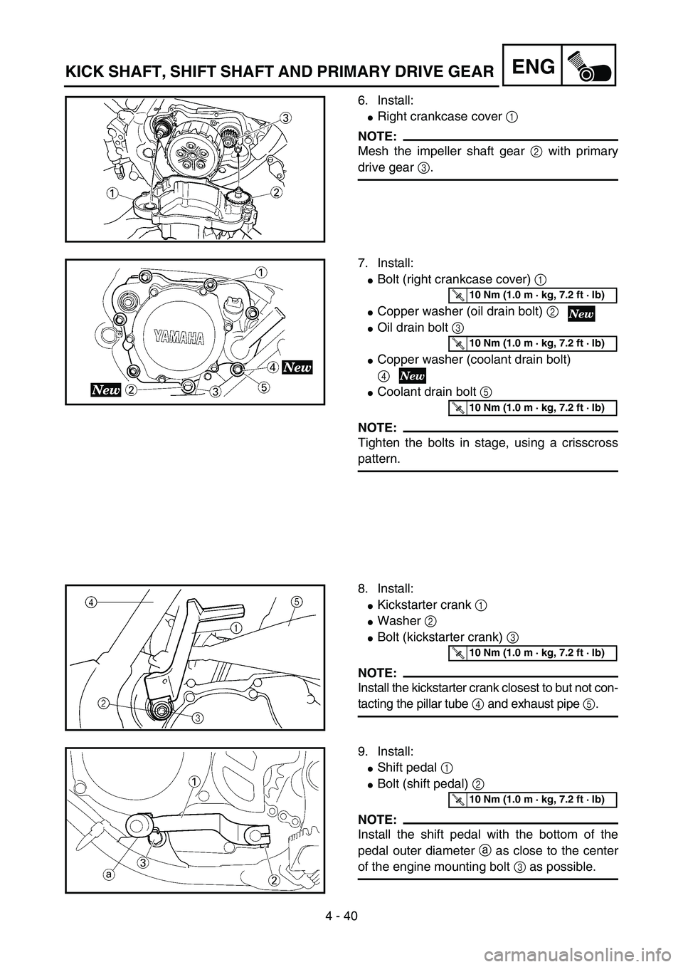
6. Install:
�Right crankcase cover 1
NOTE:
Mesh the impeller shaft gear 2 with primary
drive gear 3.
5PA41200
7. Install:
�Bolt (right crankcase cover) 1
�Copper washer (oil drain bolt) 2
�Oil drain bolt 3
�Copper washer (coolant drain bolt)
4
�Coolant drain bolt 5
NOTE:
Tighten the bolts in stage, using a crisscross
pattern.
5PA41210
T R..10 Nm (1.0 m · kg, 7.2 ft · lb)
T R..10 Nm (1.0 m · kg, 7.2 ft · lb)
T R..10 Nm (1.0 m · kg, 7.2 ft · lb)
8. Install:
�Kickstarter crank 1
�Washer 2
�Bolt (kickstarter crank) 3
NOTE:
Install the kickstarter crank closest to but not con-
tacting the pillar tube 4 and exhaust pipe 5.
5PA41220
T R..10 Nm (1.0 m · kg, 7.2 ft · lb)
9. Install:
�Shift pedal 1
�Bolt (shift pedal) 2
NOTE:
Install the shift pedal with the bottom of the
pedal outer diameter a as close to the center
of the engine mounting bolt 3 as possible.
5PA41230
T R..10 Nm (1.0 m · kg, 7.2 ft · lb)
KICK SHAFT, SHIFT SHAFT AND PRIMARY DRIVE GEAR
Page 284 of 506
4 - 44
ENG
2. Install:
�Bearing 1
NOTE:
Install the bearing by pressing its outer race
parallel.
5PA41330
Impeller shaft
1. Install:
�Impeller shaft 1
�Washer 2
�Impeller 3
NOTE:
�Take care so that the oil seal lip is not dam-
aged or the spring does not slip off its posi-
tion.
�When installing the impeller shaft, apply the
lithium soap base grease on the oil seal lip
and impeller shaft. And install the shaft while
turning it.
�Hold the impeller shaft on its width across
the flats a with spanners, etc. and install the
impeller.
5PA41340
T R..14 Nm (1.4 m · kg, 10 ft · lb)
5PA41350
2. Install:
�Gasket (water pump housing) 1
5PA41360
3. Install:
�Water pump housing 1
�Bolt (water pump housing) 2
�Copper washer (coolant drain bolt)
3
�Coolant drain bolt 4
5PA41370
T R..10 Nm (1.0 m · kg, 7.2 ft · lb)
T R..10 Nm (1.0 m · kg, 7.2 ft · lb)
WATER PUMP
Page 342 of 506
5 - 9
CHASFRONT BRAKE AND REAR BRAKE
EC5A0000
FRONT BRAKE AND REAR BRAKE
EC5A8000
FRONT BRAKE
5PA50250
Extent of removal:
1 Brake hose removal
2 Brake caliper removal
3 Brake master cylinder removal
Extent of removal Order Part name Q’ty Remarks
Preparation for removalFRONT BRAKE REMOVAL
Hold the machine by placing the
suitable stand under the engine.
WARNING
Support the machine securely so there is no
danger of it falling over.
Drain the brake fluid. Refer to “REMOVAL POINTS”.
1 Protector 1
2 Brake hose holder 1
3 Union bolt 2
4 Brake hose 1
5 Brake caliper support bolt 1
6 Brake caliper 1 Refer to “REMOVAL POINTS”.
7Brake lever 1
8 Brake master cylinder bracket 1
9 Brake master cylinder 1
2
3
132
Page 344 of 506
5 - 10
CHAS
EC5A8100
REAR BRAKE
5PAR0016
Extent of removal:
1 Brake caliper removal
2 Brake hose removal
3 Brake master cylinder removal
Extent of removal Order Part name Q’ty Remarks
Preparation for removalREAR BRAKE REMOVAL
Hold the machine by placing the
suitable stand under the engine.
WARNING
Support the machine securely so there is nodanger of it falling over.
Drain the brake fluid. Refer to “REMOVAL POINTS”.
1 Protector 1
2 Pad pin 2 Loosen when disassembling the caliper.
3 Brake caliper 1
4 Brake hose holder 2
5 Union bolt 2
6 Brake hose 1
7 Brake pedal 1
8 Reservoir tank 1
9 Reservoir hose 1
10 Brake master cylinder 1
3
1
321
FRONT BRAKE AND REAR BRAKE
Page 380 of 506
5 - 28
CHAS
EC558000
FRONT FORK DISASSEMBLY
5PA50830
Extent of removal:
1 Oil seal removal
2 Damper rod removal
Extent of removal Order Part name Q’ty Remarks
FRONT FORK DISASSEMBLY
1 Front fork cap bolt 1 Use special tool.
Refer to “REMOVAL POINTS”.
2 Fork spring 1 Drain the fork oil.
3 Dust seal 1
Refer to “REMOVAL POINTS”.
4 Stopper ring 1
5 Inner tube 1
6 Outer tube 1
7 Piston metal 1
8 Slide metal 1
9 Oil seal washer 1
0 Oil seal 1
A Spring guide 1
B Base valve 1 Use special tool.
C Damper rod 1 Refer to “REMOVAL POINTS”.
1
2
FRONT FORK

 5 - 9
CHASFRONT BRAKE AND REAR BRAKE
EC5A0000
FRONT BRAKE AND REAR BRAKE
EC5A8000
FRONT BRAKE
5PA50250
Extent of removal:
1 Brake hose removal
2 Brake caliper removal
3 Brake master cylinder removal
E")
 5 - 10
CHAS
EC5A8100
REAR BRAKE
5PAR0016
Extent of removal:
1 Brake caliper removal
2 Brake hose removal
3 Brake master cylinder removal
Extent of removal Order Part name Q’ty Remarks
Preparation fo")
 5 - 28
CHAS
EC558000
FRONT FORK DISASSEMBLY
5PA50830
Extent of removal:
1 Oil seal removal
2 Damper rod removal
Extent of removal Order Part name Q’ty Remarks
FRONT FORK DISASSEMBLY
1 Front fork ca")