Page 87 of 642

SPEC
2 - 16
MAINTENANCE SPECIFICATIONS
NOTE:
- marked portion shall be checked for torque tightening after break-in or before each race.Part to be tightened Thread size Q’tyTightening torque
Nm m·kg ft·lb
Rear wheel axle and nut M20 × 1.5 1 125 12.5 90
Driven sprocket and wheel hub M8 × 1.25 6 42 4.2 30
Nipple (spoke)–72 3 0.3 2.2
Disc cover and rear brake caliper M6 × 1.0 2 7 0.7 5.1
Protector and rear brake caliper M6 × 1.0 2 7 0.7 5.1
Chain puller adjust bolt and locknut M8 × 1.25 2 16 1.6 11
Engine mounting:
Engine upper bracket and frame M10 × 1.25 2 55 5.5 40
Engine lower bracket and frame M8 × 1.25 4 34 3.4 24
Engine and frame (front) M10 × 1.25 1 69 6.9 50
Engine and frame (upper) M10 × 1.25 1 55 5.5 40
Engine and frame (lower) M10 × 1.25 1 69 6.9 50
Engine guard (lower) M8 × 1.25 1 34 3.4 24
Engine skid plate mounting M6 × 1.0 6 10 1.0 7.2
CDI unit bracket mounting M6 × 1.0 1 10 1.0 7.2
Pivot shaft and nut M16 × 1.5 1 85 8.5 61
Relay arm and swingarm M14 × 1.5 1 80 8.0 58
Relay arm and connecting rod M14 × 1.5 1 80 8.0 58
Connecting rod and frame M14 × 1.5 1 80 8.0 58
Rear shock absorber and frame M10 × 1.25 1 56 5.6 40
Rear shock absorber and relay arm M10 × 1.25 1 53 5.3 38
Rear frame and frame (upper) M8 × 1.25 1 32 3.2 23
Rear frame and frame (lower) M8 × 1.25 2 29 2.9 21
Swingarm and brake hose holder M5 × 0.8 4 1 0.1 0.7
Swingarm and patch M4 × 0.7 4 2 0.2 1.4
Drive chain tensioner mounting (upper) M8 × 1.25 1 19 1.9 13
Drive chain tensioner mounting (lower) M8 × 1.25 1 20 2.0 14
Chain support and swingarm M6 × 1.0 3 7 0.7 5.1
Seal guard and swingarm M5 × 0.8 4 6 0.6 4.3
Fuel tank mounting M6 × 1.0 2 10 1.0 7.2
Fuel tank and fuel cock M6 × 1.0 2 7 0.7 5.1
Fuel tank and seat set bracket M6 × 1.0 1 7 0.7 5.1
Fuel tank and hooking screw (fitting band) M6 × 1.0 1 7 0.7 5.1
Fuel tank and fuel tank bracket M6 × 1.0 4 7 0.7 5.1
Seat mounting M8 × 1.25 2 23 2.3 17
Side cover mounting M6 × 1.0 2 7 0.7 5.1
Air scoop and fuel tank M6 × 1.0 6 6 0.6 4.3
Air scoop and radiator panel (lower) M6 × 1.0 2 6 0.6 4.3
Front fender mounting M6 × 1.0 4 7 0.7 5.1
Rear fender mounting (front) M6 × 1.0 2 7 0.7 5.1
Rear fender mounting (rear) M6 × 1.0 2 12 1.2 8.7
Number plate M6 × 1.0 1 7 0.7 5.1
Page 144 of 642
3 - 3
INSP
ADJ
MAINTENANCE INTERVALS
FRONT FORK OIL SEAL AND DUST
SEAL
Clean and lube
● ● Lithium base grease
REAR SHOCK ABSORBER
Inspect and adjust
Lube
Retighten
●
●
●
●
●
(After
rain ride)
● Molybdenum disulfide
grease
CHAIN GUARD AND ROLLERS
Inspect
● ●
SWINGARM
Inspect, lube and retighten
● ● Molybdenum disulfide
grease
RELAY ARM, CONNECTING ROD
Inspect, lube and retighten
● ● Molybdenum disulfide
grease
STEERING HEAD
Inspect free play and retighten
Clean and lube
Replace bearing
● ●
●
● Lithium base grease
TIRE, WHEELS
Inspect air pressure, wheel run-out,
tire wear and spoke looseness
Retighten sprocket bolt
Inspect bearings
Replace bearings
Lubricate
●
●
●
●
●
●
●
Lithium base grease
THROTTLE, CONTROL CABLE
Check routing and connection
Lubricate
●
●
●
● Yamaha cable lube or
SAE 10W-30 motor oil
HOT STARTER, CLUTCH LEVER
Inspect free play
●
ItemAfter
break-inEvery
race
Every
third
(or
500 km)Every
fifth
(or
1,000 km)As re-
quiredRemarks
Page 534 of 642
5 - 50
CHASSWINGARM
EC570000
SWINGARM
Extent of removal:1 Swingarm removal
Extent of removal Order Part name Q’ty Remarks
SWINGARM REMOVAL
WARNINGSupport the machine securely so there is no
danger of it falling over.
Preparation for removal Hold the machine by placing the
suitable stand under the engine.
Brake hose holder
Rear caliper
Bolt (brake pedal)
Drive chainRefer to “FRONT BRAKE AND REAR
BRAKE” section.
Shift the brake pedal backward.
1 Chain support 1
2 Chain tensioner (lower) 1
3 Bolt (rear shock absorber-relay
arm)1 Hold the swingarm.
4 Bolt (connecting rod) 1
5 Pivot shaft 1
6 Swingarm 1
1
Page 536 of 642
5 - 51
CHASSWINGARM
EC578000
SWINGARM DISASSEMBLY
Extent of removal:1 Swingarm disassembly2 Connecting rod removal and disassembly
3 Relay arm removal and disassembly
Extent of removal Order Part name Q’ty Remarks
SWINGARM DISASSEMBLY
1 Cap 2
2 Relay arm 1
3 Connecting rod 1
4 Collar 2
5 Oil seal 2
6 Thrust bearing 2
7 Bush 2
8 Oil seal 8
9 Bearing 8 Refer to “REMOVAL POINTS”.
1
2
32
3
Page 538 of 642
5 - 52
CHASSWINGARM
EC573000
REMOVAL POINTS
EC573200
Bearing
1. Remove:
�Bearing 1
NOTE:
Install the bearing by pressing its outer race.
EC574010
INSPECTION
Wash the bearings, bushes, collars, and cov-
ers in a solvent.
EC574111
Swingarm
1. Inspect:
�Bearing 1
�Bush 2
Free play exists/unsmooth revolution/
rust → Replace bearing and bush as a
set.
2. Inspect:
�Oil seal 3
Damage → Replace.
EC574210
Relay arm
1. Inspect:
�Bearing (polylube bearing) 1
�Collar 2
Free play exists/unsmooth revolution/rust
→ Replace bearing and collar as a set.
2. Inspect:
�Bearing (polylube bearing) 1
Loss of solid lubrication → Replace.
�Oil seal 3
Damage → Replace.
NOTE:
Polylube bearings, with solid lubrication, have
been adopted with the intent to make the nee-
dle bearings, used in this model, maintenance
free. With polylube bearings, no grease nipple
and regular lubrication is necessary. However,
grease should be applied to all oil seals and
collars when removed or installed.
Page 542 of 642
5 - 54
CHASSWINGARM
2. Install:
�Bearing 1
�Oil seal 2
To relay arm.
NOTE:
�Apply the molybdenum disulfide grease on
the bearing when installing.
�Install the bearing by pressing it on the side
having the manufacture’s marks or numbers.
3. Install:
�Bearing 1
�Oil seal 2
To connecting rod.
NOTE:
�Apply the molybdenum disulfide grease on
the bearing when installing.
�Install the bearing by pressing it on the side
having the manufacture’s marks or numbers.
Installed depth of bearings a:
5 mm (0.20 in)
Installed depth of bearings a:
5 mm (0.20 in)
Swingarm
1. Install:
�Bush 1
�Thrust bearing 2
�Oil seal 3
�Collar 4
To swingarm 5.
NOTE:
Apply the molybdenum disulfide grease on the
bushes, thrust bearings and oil seal lips.
2. Install:
�Collar 1
To relay arm 2.
NOTE:
Apply the molybdenum disulfide grease on the
collars and oil seal lips.
Page 544 of 642
5 - 55
CHASSWINGARM
3. Install:
�Collar 1
To connecting rod 2.
NOTE:
Apply the molybdenum disulfide grease on the
collar and oil seal lips.
4. Install:
�Connecting rod 1
�Bolt (connecting rod) 2
�Plain washer 3
�Nut (connecting rod) 4
To relay arm 5.
NOTE:
Apply the molybdenum disulfide grease on the
bolt.
T R..80 Nm (8.0 m · kg, 58 ft · lb)
5. Install:
�Relay arm 1
�Bolt (relay arm) 2
�Plain washer 3
�Nut (relay arm) 4
To swingarm.
NOTE:
�Apply the molybdenum disulfide grease on
the bolt.
�Do not tighten the nut yet.
6. Install:
�Swingarm 1
�Pivot shaft 2
NOTE:
�Apply the molybdenum disulfide grease on
the pivot shaft.
�Insert the pivot shaft from right side.
T R..85 Nm (8.5 m · kg, 61 ft · lb)
7. Check:
�Swingarm side play a
Free play exists → Replace thrust bear-
ing.
�Swingarm up and down movement b
Unsmooth movement/binding/rough
spots → Grease or replace bearings,
bushes and collars.
Page 546 of 642
5 - 56
CHASSWINGARM
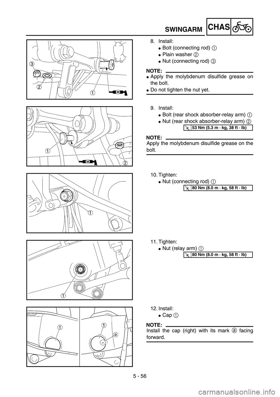
8. Install:
�Bolt (connecting rod) 1
�Plain washer 2
�Nut (connecting rod) 3
NOTE:
�Apply the molybdenum disulfide grease on
the bolt.
�Do not tighten the nut yet.
9. Install:
�Bolt (rear shock absorber-relay arm) 1
�Nut (rear shock absorber-relay arm) 2
NOTE:
Apply the molybdenum disulfide grease on the
bolt.
T R..53 Nm (5.3 m · kg, 38 ft · lb)
10. Tighten:
�Nut (connecting rod) 1
T R..80 Nm (8.0 m · kg, 58 ft · lb)
11. Tighten:
�Nut (relay arm) 1
T R..80 Nm (8.0 m · kg, 58 ft · lb)
12. Install:
�Cap 1
NOTE:
Install the cap (right) with its mark a facing
forward.