Page 348 of 642
4 - 55
ENG
OIL FILTER, WATER PUMP AND CRANKCASE COVER
(RIGHT)
OIL FILTER, WATER PUMP AND CRANKCASE COVER (RIGHT)
OIL FILTER, WATER PUMP AND CRANKCASE COVER (RIGHT)
Extent of removal:1 Oil filter removal2 Water pump removal
3 Crankcase cover (right) removal
Extent of removal Order Part name Q’ty Remarks
OIL FILTER, WATER PUMP
AND CRANKCASE COVER
(RIGHT) REMOVAL
Preparation for removal Drain the engine oil. Refer to “ENGINE OIL REPLACEMENT”
section in the CHAPTER 3.
Drain the coolant. Refer to “COOLANT REPLACEMENT”
section in the CHAPTER 3.
Exhaust pipe Refer to “EXHAUST PIPE AND
SILENCER” section.
Brake pedal Refer to “ENGINE REMOVAL” section.
Clutch cover Refer to “CLUTCH” section.
1 Oil filter cover 1
2 Oil filter 1
3 Coolant pipe 2 1
4 Water pump housing 1
5 Pin 2
6 Oil delivery pipe 1
1
2
3
Page 400 of 642
4 - 81
ENGENGINE REMOVAL
Extent of removal:1 Engine removal
Extent of removal Order Part name Q’ty Remarks
1 Engine skid plate (front) 1
2 Neutral switch 1
3 Oil hose 2
4 Chain cover 1
5 Nut (drive sprocket) 1
Refer to “REMOVAL POINTS”. 6 Lock washer 1
7 Drive sprocket 1
8 Clip 1
9 Bolt (brake pedal) 1
10 Brake pedal 1
11 Engine upper bracket (right) 1
12 Engine upper bracket (left) 1
13 Engine lower bracket 2
14 Engine mounting bolt 3
15 Pivot shaft 1
Refer to “REMOVAL POINTS”.
16 Engine 1
1
Page 402 of 642
4 - 82
ENGENGINE REMOVAL
EC4M3000
REMOVAL POINTS
EC4F3100
Drive sprocket
1. Remove:
�Nut (drive sprocket) 1
�Lock washer 2
NOTE:
�Straighten the lock washer tab.
�Loosen the nut while applying the rear brake.
2. Remove:
�Drive sprocket 1
�Drive chain 2
NOTE:
Remove the drive sprocket together with the
drive chain.
EC4M3301
Engine removal
1. Remove:
�Pivot shaft 1
NOTE:
If the pivot shaft is pulled all the way out, the
swingarm will come loose. If possible, insert a
shaft of similar diameter into the other side of
the swingarm to support it.
2. Remove:
�Engine 1
From right side.
NOTE:
Make sure that the couplers, hoses and cables
are disconnected.
1
Page 404 of 642
 4 - 83
ENGENGINE REMOVAL
EC4M5000
ASSEMBLY AND INSTALLATION
Engine installation
1. Install:
�Engine 1
Install the engine from right side.
�Pivot shaft 2
�Engine mounting bolt (lower) 3
�Engine lowe")
4 - 83
ENGENGINE REMOVAL
EC4M5000
ASSEMBLY AND INSTALLATION
Engine installation
1. Install:
�Engine 1
Install the engine from right side.
�Pivot shaft 2
�Engine mounting bolt (lower) 3
�Engine lower bracket 4
�Bolt (engine lower bracket) 5
�Engine mounting bolt (front) 6
�Bolt (engine guard) 7
�Engine upper bracket (right) 8
�Engine upper bracket (left) 9
�Bolt (engine upper bracket) 0
�Engine mounting bolt (upper) A
�Engine skid plate (front) B
�Bolt (engine skid plate) C
NOTE:
Apply the molybdenum disulfide grease on the
pivot shaft.
EC4M5211
Brake pedal
1. Install:
�Spring
�Brake pedal 1
�O-ring 2
�Bolt (brake pedal) 3
�Clip 4
NOTE:
�Apply the lithium soap base grease on the
bolt, O-rings and brake pedal bracket.
�Install the clip with its stopper portion a fac-
ing inward.
Drive sprocket
1. Install:
�Drive sprocket 1
�Drive chain 2
NOTE:
Install the drive sprocket together with the
drive chain.
T R..85 Nm (8.5 m · kg, 61 ft · lb)
T R..69 Nm (6.9 m · kg, 50 ft · lb)
T R..34 Nm (3.4 m · kg, 24 ft · lb)
T R..69 Nm (6.9 m · kg, 50 ft · lb)
T R..34 Nm (3.4 m · kg, 24 ft · lb)
T R..55 Nm (5.5 m · kg, 40 ft · lb)
T R..55 Nm (5.5 m · kg, 40 ft · lb)
T R..10 Nm (1.0 m · kg, 7.2 ft · lb)
New
T R..26 Nm (2.6 m · kg, 19 ft · lb)
Page 406 of 642
4 - 84
ENGENGINE REMOVAL
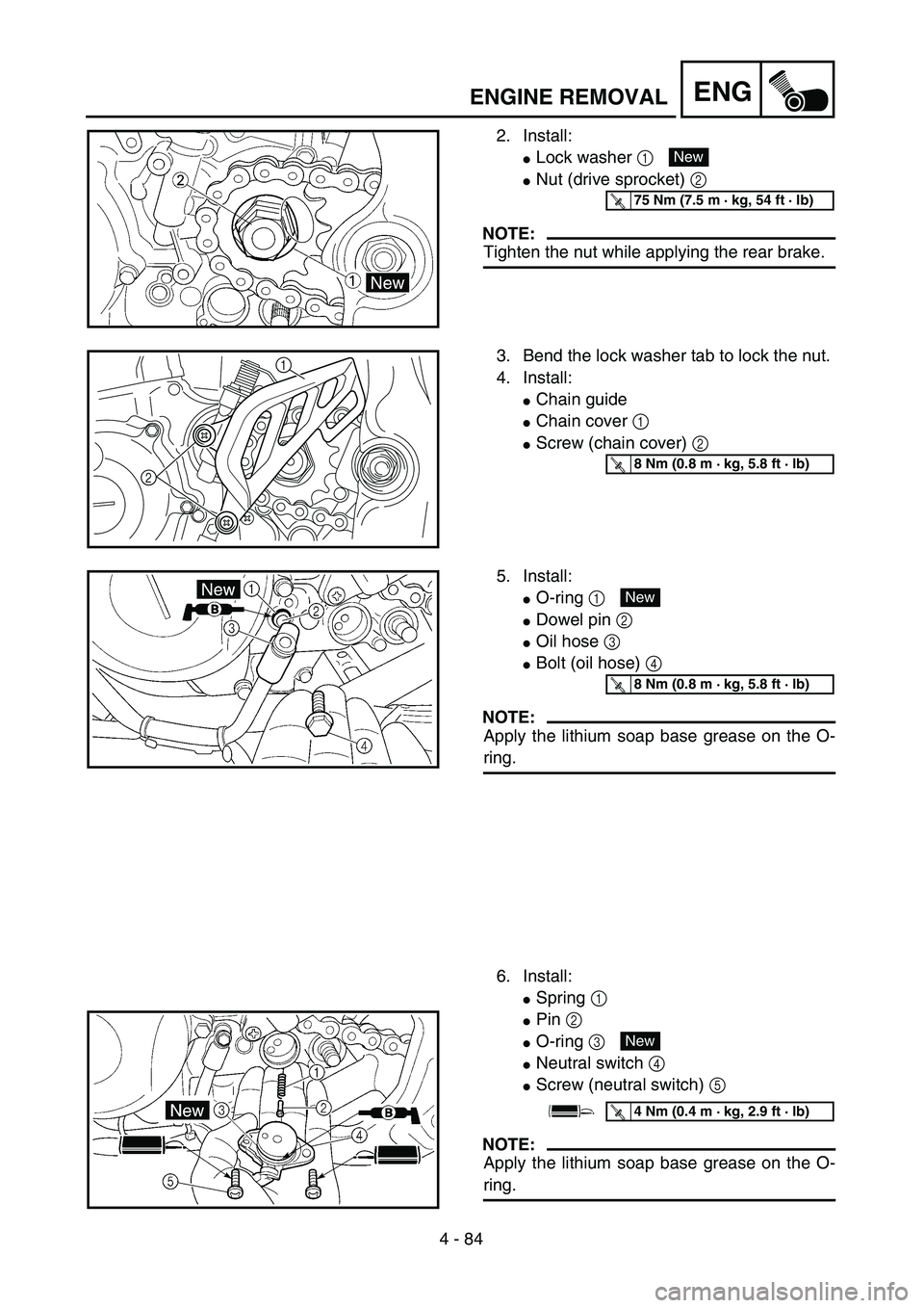
2. Install:
�Lock washer 1
�Nut (drive sprocket) 2
NOTE:
Tighten the nut while applying the rear brake.
New
T R..75 Nm (7.5 m · kg, 54 ft · lb)
3. Bend the lock washer tab to lock the nut.
4. Install:
�Chain guide
�Chain cover 1
�Screw (chain cover) 2
21T R..8 Nm (0.8 m · kg, 5.8 ft · lb)
5. Install:
�O-ring 1
�Dowel pin 2
�Oil hose 3
�Bolt (oil hose) 4
NOTE:
Apply the lithium soap base grease on the O-
ring.
6. Install:
�Spring 1
�Pin 2
�O-ring 3
�Neutral switch 4
�Screw (neutral switch) 5
NOTE:
Apply the lithium soap base grease on the O-
ring.
New
T R..8 Nm (0.8 m · kg, 5.8 ft · lb)
New
T R..4 Nm (0.4 m · kg, 2.9 ft · lb)
Page 436 of 642
5 - 1
CHAS
EC500000
CHASSIS
EC590000
FRONT WHEEL AND REAR WHEEL
EC598000
FRONT WHEEL
FRONT WHEEL AND REAR WHEEL
Extent of removal:
1
Front wheel removal
2
Wheel bearing removal
3
Brake disc removal
Extent of removal Order Part name Q’ty Remarks
Preparation for removal
FRONT WHEEL REMOVAL
Hold the machine by placing the
suitable stand under the engine.
WARNING
Support the machine securely so there is no
danger of it falling over.
1 Hose cover 1
2 Bolt (brake hose holder) 2 Only loosening.
3 Bolt (axle holder) 4 Only loosening.
4 Nut (front wheel axle) 1
5 Front wheel axle 1
6 Front wheel 1
7 Collar 2
8 Oil seal 2
9 Bearing 2 Refer to “REMOVAL POINTS”.
10Brake disc
1
2
31
3
Page 438 of 642
5 - 2
CHAS
EC598100
REAR WHEEL
Extent of removal:
1
Rear wheel removal
2
Wheel bearing removal
3
Brake disc removal
Extent of removal Order Part name Q’ty Remarks
Preparation for removal
REAR WHEEL REMOVAL
Hold the machine by placing the
suitable stand under the engine.
WARNING
Support the machine securely so there is no
danger of it falling over.
1 Nut (rear wheel axle) 1
2 Rear wheel axle 1
3 Chain puller 2
4 Rear wheel 1 Refer to “REMOVAL POINTS”.
5 Collar 2
6 Driven sprocket 1
7 Oil seal 2
8 Circlip 1
9 Bearing 2 Refer to “REMOVAL POINTS”.
10Brake disc
1
2
31
3
FRONT WHEEL AND REAR WHEEL
Page 442 of 642
5 - 4
CHAS
FRONT WHEEL AND REAR WHEEL
EC514200
Wheel axle
1. Measure:
�
Wheel axle bends
Out of specification
→
Replace.
Use the dial gauge
1
.
NOTE:
The bending value is shown by one half of the
dial gauge reading.
WARNING
Do not attempt to straighten a bent axle.
Wheel axle bending limit:
0.5 mm (0.020 in)
EC594200
Brake disc
1. Measure:
�
Brake disc deflection (only rear brake
disc)
Use the dial gauge
1
.
Out of specification
→
Inspect wheel
runout.
If wheel runout is in good condition,
replace the brake disc.
2. Measure:
�
Brake disc thickness
a
Out of limit
→
Replace.
Disc deflection limit:
Standard
Rear —0.15 mm
(0.006 in)
Disc wear limit:
Standard
Front 3.0 mm (0.12 in) 2.5 mm (0.10 in)
Rear 4.0 mm (0.16 in) 3.5 mm (0.14 in)
 4 - 55
ENG
OIL FILTER, WATER PUMP AND CRANKCASE COVER
(RIGHT)
OIL FILTER, WATER PUMP AND CRANKCASE COVER (RIGHT)
OIL FILTER, WATER PUMP AND CRANKCASE COVER (RIGHT)
Extent of removal:1 Oil filter remov")
 4 - 81
ENGENGINE REMOVAL
Extent of removal:1 Engine removal
Extent of removal Order Part name Q’ty Remarks
1 Engine skid plate (front) 1
2 Neutral switch 1
3 Oil hose 2
4 Chain cover 1
5 Nut (drive")


5 - 1
CHAS
EC500000
CHASSIS
EC590000
FRONT WHEEL AND REAR WHEEL
EC598000
FRONT WHEEL
FRONT WHEEL AND REAR WHEEL
Extent of removal:
1
Front wheel removal
2
Wheel bearing removal")

5 - 2
CHAS
EC598100
REAR WHEEL
Extent of removal:
1
Rear wheel removal
2
Wheel bearing removal
3
Brake disc removal
Extent of removal Order Part name Q’ty Remarks
Preparation for")
