Page 422 of 568
5-31
CHASFRONT FORK
EC554700
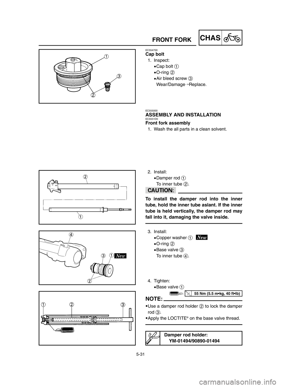
Cap bolt
1. Inspect:
9Cap bolt 1
9O-ring 2
9Air bleed screw 3
Wear/Damage�Replace.
EC555000
ASSEMBLY AND INSTALLATIONEC5551D0
Front fork assembly
1. Wash the all parts in a clean solvent.
2. Install:
9Damper rod 1
To inner tube 2.
cC
To install the damper rod into the inner
tube, hold the inner tube aslant. If the inner
tube is held vertically, the damper rod may
fall into it, damaging the valve inside.
3. Install:
9Copper washer 1
9O-ring 2
9Base valve 3
To inner tube 4.
4. Tighten:
9Base valve 1
NOTE:
9Use a damper rod holder 2to lock the damper
rod 3.
9Apply the LOCTITE
®on the base valve thread.
Damper rod holder:
YM-01494/90890-01494
55 Nm (5.5 m•kg, 40 ft•lb)
5XE-9-30-5B 4/30/03 9:41 AM Page 12
Page 424 of 568
5-32
CHASFRONT FORK
5. Install:
9Spring guide 1
9Locknut 2
To damper rod 3.
NOTE:
9Install the spring guide with its smaller dia. end
afacing downward.
9With its thread bfacing upward, fully finger
tighten the locknut onto the damper rod.
6. Install:
9Dust seal 1
9Stopper ring 2
9Oil seal 3
9Oil seal washer 4
9Slide metal 5
To inner tube 6.
NOTE:
9Apply the fork oil on the inner tube.
9When installing the oil seal, use vinyl seat a
with fork oil applied to protect the oil seal lip.
9Install the oil seal with its manufacture's marks
or number facing the axle holder side.
9Install the oil seal washer with its projections b
facing upward.
7. Install:
9Piston metal 1
NOTE:
Install the piston metal onto the slot on inner
tube.
8. Install:
9Outer tube 1
To inner tube 2.
5XE-9-30-5B 4/30/03 9:41 AM Page 14
Page 426 of 568
5-33
CHASFRONT FORK
9. Install:
9Slide metal 1
9Oil seal washer 2
To outer tube slot.
NOTE:
Press the slide metal into the outer tube with
fork seal driver 3.
10. Install:
9Oil seal 1
NOTE:
Press the oil seal into the outer tube with fork
seal driver 2.
11. Install:
9Stopper ring 1
NOTE:
Fit the stopper ring correctly in the groove in the
outer tube.
12. Install:
9Dust seal 1
NOTE:
Apply the lithium soap base grease on the inner
tube.
Fork seal driver:
YM-01442/90890-01442
Fork seal driver:
YM-01442/90890-01442
5XE-9-30-5B 4/30/03 9:41 AM Page 16
Page 428 of 568

5-34
CHASFRONT FORK
13. Check:
9Inner tube smooth movement
Tightness/Binding/Rough spots �Repeat the
steps 2 to 12.
14. Compress the front fork fully.
15. Fill:
9Front fork oil
Until outer tube top surface with recom-
mended fork oil 1.
cC
9Be sure to use recommended fork oil. If
other oils are used, they may have an ex-
cessively adverse effect on the front fork
performance.
9Never allow foreign materials to enter the
front fork.
16. After filling, pump the damper rod 1slowly
up and down more than 10 times to distrib-
ute the fork oil.
17. Fill:
9Front fork oil
Until outer tube top surface with recom-
mended fork oil once more.
18. After filling, pump the outer tube 1slowly
up and down (about 200 mm (7.9 in) stroke)
to distribute the fork oil once more.
NOTE:
Be careful not to excessive full stroke. A stroke
of 200 mm (7.9 in) or more will cause air to en-
ter. In this case, repeat the steps 15 to 18.
Recommended oil:
Suspension oil “01”
5XE-9-30-5B 4/30/03 9:41 AM Page 18
Page 430 of 568

5-35
CHASFRONT FORK
19. Wait ten minutes until the air bubbles have
been removed from the front fork, and the
oil has dispense evenly in system before
setting recommended oil level.
NOTE:
Fill with the fork oil up to the top end of the outer
tube, or the fork oil will not spread over to every
part of the front forks, thus making it impossible
to obtain the correct level.
Be sure to fill with the fork oil up to the top of the
outer tube and bleed the front forks.
20. Measure:
9Oil level (left and right) a
Out of specification � Adjust.
NOTE:
Be sure to install the spring guide 2when
checking the oil level.
w
Never fail to make the oil level adjustment
between the maximum and minimum level
and always adjust each front fork to the
same setting. Uneven adjustment can
cause poor handling and loss of stability.
Standard oil level:
125 mm (4.92 in)
Extent of adjustment:
105~135 mm (4.13~5.31 in)
From top of outer tube with
inner tube and damper rod
1 1
fully compressed without spring.
5XE-9-30-5B 4/30/03 9:41 AM Page 20
Page 432 of 568
5-36
CHASFRONT FORK
21. Measure:
9Distance a
Out of specification�Turn into the locknut.
23. Install:
9Push rod 1
9Fork spring 2
NOTE:
9Install the fork spring with the damper rod 3
pulled up.
9After installing the fork spring , hold the damper
rod end so that it will not go down.
24. Install:
9Spring seat 1
9Cap bolt 2
NOTE:
Fully finger tighten the cap bolt onto the damper
rod.
25. Tighten:
9Cap bolt (locknut) 1
NOTE:
Hold the locknut 2and tighten the cap bolt with
specified torque.
22. Loosen:
9Rebound damping adjuster 1
NOTE:
9Loosen the rebound damping adjuster finger
tight.
9Record the set position of the adjuster (the
amount of turning out the fully turned in posi-
tion).
Distance a a
:
19 mm (0.75 in) or more
Between damper rod 1 1
top and
locknut 2 2
top.
29 Nm (2.9 m•kg, 21 ft•lb)
5XE-9-30-5B 4/30/03 9:42 AM Page 22
Page 434 of 568
5-37
CHASFRONT FORK
2. Tighten:
9Cap bolt 1
3. Adjust:
9Front fork top end a
30 Nm (3.0 m•kg, 22 ft•lb)
Front fork top end (standard) a a
:
5 mm (0.20 in)
26. Install:
9Cap bolt 1
To outer tube.
NOTE:
Temporarily tighten the cap bolt.
27. Install:
9Protector guide 1
EC5552A1
Installation
1. Install:
9Front fork 1
NOTE:
9Temporarily tighten the pinch bolts (under
bracket).
9Do not tighten the pinch bolts (handle crown)
yet.
4. Tighten:
9Pinch bolt (handle crown) 1
9Pinch bolt (under bracket) 2
cC
Tighten the under bracket to specified
torque. If torqued too much, it may cause
the front fork to malfunction.
23 Nm (2.3 m•kg, 17 ft•lb)
20 Nm (2.0 m•kg, 14 ft•lb)
5XE-9-30-5B 4/30/03 9:42 AM Page 24
Page 436 of 568
5-38
CHASFRONT FORK
7. Adjust:
9Rebound damping force
NOTE:
Turn in the damping adjuster 1finger-tight and
then turn out to the originally set position.
5. Install:
9Brake hose holder 1
9Caliper 2
9Bolt (caliper) 3
NOTE:
Fit the brake hose holder cut aover the projec-
tion bon the front fork and clamp the brake
hose.
6. Install:
9Brake hose holder 1
9Bolt (brake hose holder) 2
9Protector 3
9Bolt (protector) 4
NOTE:
When installing the brake hose holder, align the
top aof the brake hose neck with the brake
hose holder bottom b. Then pass the brake
hose 5in front of the axle boss cand fit it into
the hose groove dso that the brake hose does
not contact the nut (wheel axle).
23 Nm (2.3 m•kg, 17 ft•lb)
10 Nm (1.0 m•kg, 7.2 ft•lb)
10 Nm (1.0 m•kg, 7.2 ft•lb)
5XE-9-30-5B 4/30/03 9:42 AM Page 26


Front fork top end (standard) a a
:
5 mm (0.20 in)
26. Install:
9Cap bolt 1
To outer tube.
N")
