Page 408 of 568

5-24
CHASFRONT BRAKE AND REAR BRAKE
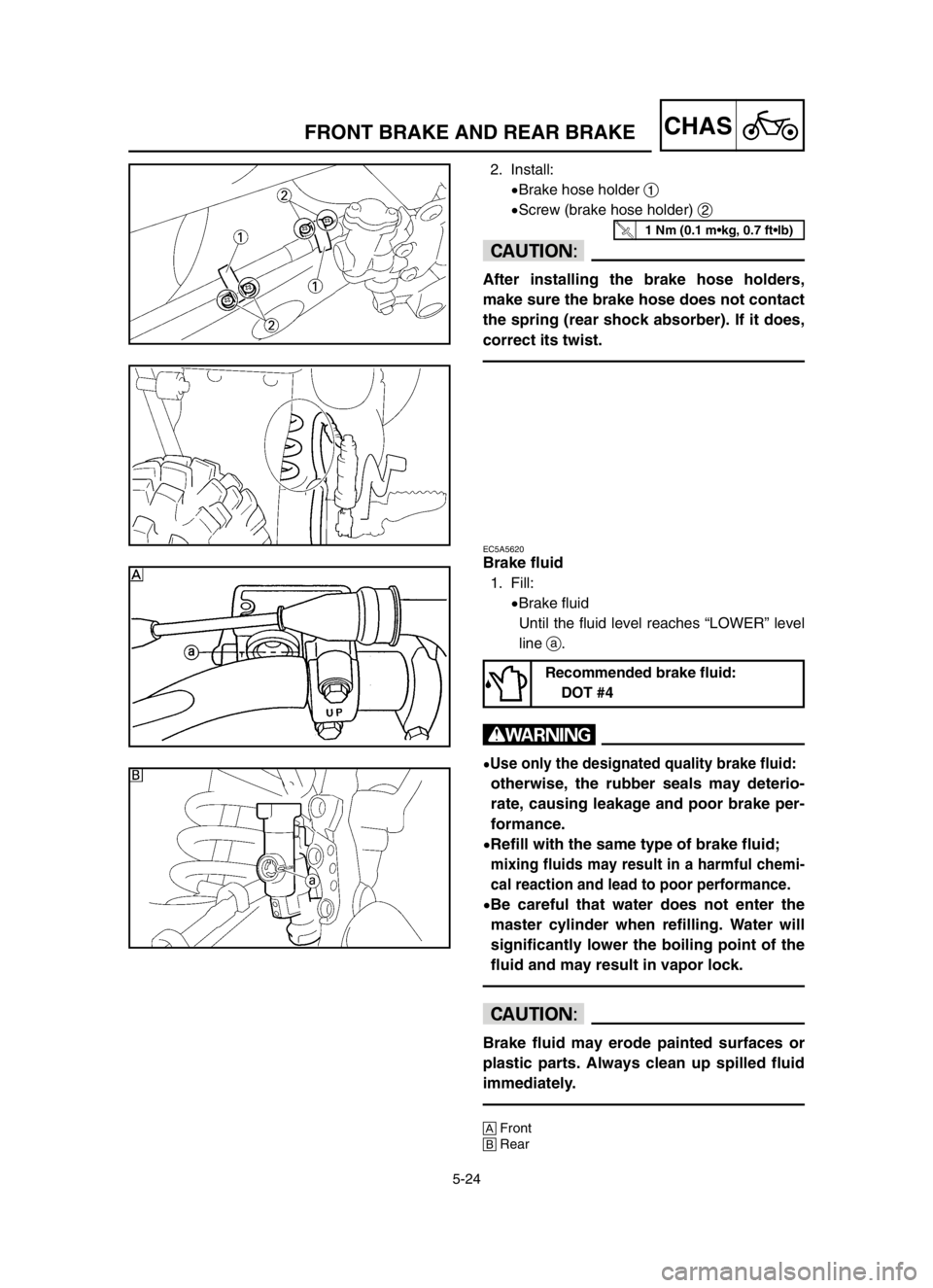
2. Install:
9Brake hose holder 1
9Screw (brake hose holder) 2
cC
After installing the brake hose holders,
make sure the brake hose does not contact
the spring (rear shock absorber). If it does,
correct its twist.
EC5A5620
Brake fluid
1. Fill:
9Brake fluid
Until the fluid level reaches “LOWER” level
line a.
w
9Use only the designated quality brake fluid:
otherwise, the rubber seals may deterio-
rate, causing leakage and poor brake per-
formance.
9Refill with the same type of brake fluid;
mixing fluids may result in a harmful chemi-
cal reaction and lead to poor performance.
9Be careful that water does not enter the
master cylinder when refilling. Water will
significantly lower the boiling point of the
fluid and may result in vapor lock.
cC
Brake fluid may erode painted surfaces or
plastic parts. Always clean up spilled fluid
immediately.
AFront
BRear
Recommended brake fluid:
DOT #4
1 Nm (0.1 m•kg, 0.7 ft•lb)
5XE-9-30-5A 4/28/03 6:07 PM Page 48
Page 462 of 568
5-51
CHASSWINGARM
Extent of removal Order Part name Q’ty Remarks
SWINGARM REMOVAL
Preparation for
Hold the machine by placing the
removalsuitable stand under the engine.
Brake hose holderRefer to “FRONT BRAKE AND
Rear caliperREAR BRAKE”section.
Bolt (brake pedal) Shift the brake pedal backward.
Drive chain
1 Chain support 1
2 Chain tensioner (lower) 1
3
Bolt (rear shock absorber-relay arm)1 Hold the swingarm.
4 Bolt (connecting rod) 1
5 Pivot shaft 1
6 Swingarm 1 Extent of removal:
1Swingarm removal
1
w
Support the machine securely so there is no dan-
ger of it falling over.
EC570000
SWINGARM
53 Nm (5.3 m•kg, 38 ft•lb)
80 Nm (8.0 m•kg, 58 ft•lb)
19 Nm (1.9 m•kg, 13 ft•lb)
7 Nm (0.7 m•kg, 5.1 ft•lb)
85 Nm (8.5 m•kg, 61 ft•lb)
5XE-9-30-5D 4/28/03 6:02 PM Page 2
Page 558 of 568

7-24
TUNSETTING
EC72H010
Suspension setting
9Front fork
NOTE:
9If any of the following symptoms is experienced with the standard position as the base, make reset-
ting by reference to the adjustment procedure given in the same chart.
9Before any change, set the rear shock absorber sunken length to the standard figure 90~100 mm
(3.5~3.9 in).
Section
Symptom
JumpLarge
Medium Small Check Adjust
gap gap gap
Compression damping Turn adjuster counterclockwise (about 2 clicks)
Stiff over entire to decrease damping.
range111Oil level (oil amount) Decrease oil level by about 5~10 mm (0.2~0.4
in).
Spring Replace with soft spring.
Unsmooth Outer tube Check for any bends, dents, and other notice-
movement over 1111Inner tube able scars, etc. If any, replace affected parts.
entire range
Under bracket tightening Retighten to specified torque.
torque
Poor initial Rebound damping Turn adjuster counterclockwise (about 2 clicks)
movement1to decrease damping.
Oil seal Apply grease in oil seal wall.
Compression damping Turn adjuster clockwise (about 2 clicks) to in-
Soft over entire crease damping.
range, bottoming 11Oil level (oil amount) Increase oil level by about 5~10 mm (0.2~0.4
outin).
Spring Replace with stiff spring.
Stiff toward stroke
1Oil level (oil amount) Decrease oil level by about 5 mm (0.2 in).
end
Soft toward stroke
1Oil level (oil amount) Increase oil level by about 5 mm (0.2 in).
end, bottoming out
Stiff initial
1111Compression dampingTurn adjuster counterclockwise (about 2 clicks)
movement to decrease damping.
Compression damping Turn adjuster clockwise (about 2 clicks) to in-
crease damping.
Low front, tending Rebound damping Turn adjuster counterclockwise (about 2 clicks)
to lower front 11to decrease damping.
postureBalance with rear end Set sunken length for 95~100 mm (3.7~3.9 in)
when one passenger is astride seat (lower rear
posture).
Oil level (oil amount) Increase oil level by about 5 mm (0.2 in).
Compression damping Turn adjuster counterclockwise (about 2 clicks)
to decrease damping.
“Obtrusive” front, Balance with rear end Set sunken length for 90~95 mm (3.5~3.7 in)
tending to upper 11when one passenger is astride seat (upper rear
front postureposture).
Spring Replace with soft spring.
Oil lever (oil amount) Decrease oil level by about 5~10 mm (0.2~0.4
in).
5XE-9-30-7B 4/28/03 6:01 PM Page 22