Page 424 of 568
5-32
CHASFRONT FORK
5. Install:
9Spring guide 1
9Locknut 2
To damper rod 3.
NOTE:
9Install the spring guide with its smaller dia. end
afacing downward.
9With its thread bfacing upward, fully finger
tighten the locknut onto the damper rod.
6. Install:
9Dust seal 1
9Stopper ring 2
9Oil seal 3
9Oil seal washer 4
9Slide metal 5
To inner tube 6.
NOTE:
9Apply the fork oil on the inner tube.
9When installing the oil seal, use vinyl seat a
with fork oil applied to protect the oil seal lip.
9Install the oil seal with its manufacture's marks
or number facing the axle holder side.
9Install the oil seal washer with its projections b
facing upward.
7. Install:
9Piston metal 1
NOTE:
Install the piston metal onto the slot on inner
tube.
8. Install:
9Outer tube 1
To inner tube 2.
5XE-9-30-5B 4/30/03 9:41 AM Page 14
Page 432 of 568
5-36
CHASFRONT FORK
21. Measure:
9Distance a
Out of specification�Turn into the locknut.
23. Install:
9Push rod 1
9Fork spring 2
NOTE:
9Install the fork spring with the damper rod 3
pulled up.
9After installing the fork spring , hold the damper
rod end so that it will not go down.
24. Install:
9Spring seat 1
9Cap bolt 2
NOTE:
Fully finger tighten the cap bolt onto the damper
rod.
25. Tighten:
9Cap bolt (locknut) 1
NOTE:
Hold the locknut 2and tighten the cap bolt with
specified torque.
22. Loosen:
9Rebound damping adjuster 1
NOTE:
9Loosen the rebound damping adjuster finger
tight.
9Record the set position of the adjuster (the
amount of turning out the fully turned in posi-
tion).
Distance a a
:
19 mm (0.75 in) or more
Between damper rod 1 1
top and
locknut 2 2
top.
29 Nm (2.9 m•kg, 21 ft•lb)
5XE-9-30-5B 4/30/03 9:42 AM Page 22
Page 458 of 568
5-49
CHASSTEERING
4. Install:
9Ring nut 1
Tighten the ring nut using the ring nut
wrench 2.
Refer to “STEERING HEAD INSPECTION
AND ADJUSTMENT” section in the CHAP-
TER 3.
5. Check the steering shaft by turning it lock to
lock. If there is any binding, remove the
steering shaft assembly and inspect the
steering bearings.
6. Install:
9Plain washer 1
7. Install:
9Front fork 1
9Handle crown 2
NOTE:
9Temporarily tighten the pinch bolts (under
bracket).
9Do not tighten the pinch bolts (handle crown)
yet.
8. Install:
9Plain washer 1
9Steering shaft nut 2
7 Nm (0.7 m•kg, 5.1 ft•lb)
145 Nm (14.5 m•kg, 105 ft•lb)
5XE-9-30-5C 4/30/03 9:40 AM Page 22
Page 478 of 568
5-59
CHASREAR SHOCK ABSORBER
Extent of removal Order Part name Q’ty Remarks
REAR SHOCK ABSORBER
REMOVAL
Preparation forHold the machine by placing the
removalsuitable stand under the engine.
SeatRefer to “SEAT, FUEL TANK AND
SIDE COVERS” section.
SilencerRefer to “EXHAUST PIPE AND
SILENCER” section.
1 Clamp (air cleaner joint) 1 Loosen the screw (air cleaner joint).
2 Rear frame 1
3
Bolt (rear shock absorber-relay arm)1 Hold the swingarm.
4 Bolt (rear shock absorber-frame) 1
5 Rear shock absorber 1
6 Locknut 1
7 Adjuster 1
8 Spring guide (lower) 1
9 Spring guide (upper) 1
10 Spring (rear shock absorber) 1
11 Bearing 2 Refer to “REMOVAL POINTS”.
2
w
Support the machine securely so there is no dan-
ger of it falling over.
Extent of removal:1Rear shock absorber removal 2Rear shock absorber disassembly
1
56 Nm (5.6 m•kg, 40 ft•lb)
53 Nm (5.3 m•kg, 38 ft•lb)
32 Nm (3.2 m•kg, 23 ft•lb)
EC580000
REAR SHOCK ABSORBER
29 Nm (2.9 m•kg, 21 ft•lb)
5XE-9-30-5D 4/28/03 6:02 PM Page 18
Page 486 of 568
5-63
CHASREAR SHOCK ABSORBER
EC5852B5
Rear shock absorber
1. Install:
9Dust seal 1
9O-ring 2
9Collar 3
NOTE:
9Apply the molybdenum disulfide grease on the
bearing.
9Apply the lithium soap base grease on the dust
seals, O-rings and collars.
2. Install:
9Bush 1
9Collar 2
9Dust seal 3
NOTE:
9Apply the molybdenum disulfide grease on the
bearing.
9Apply the lithium soap base grease on the
bush, collars and dust seals.
9Install the dust seals with their lips facing out-
ward.
3. Adjust:
9Spring length (installed) a
*For EUROPE
NOTE:
The length of the spring (installed) changes 1.5
mm (0.06 in) per turn of the adjuster.
cC
Never attempt to turn the adjuster beyond
the maximum or minimum setting.
4. Tighten:
9Locknut 1
Spring length (installed) a
a
:
Standard
length
248 mm (9.76 in)
*265 mm (10.43 in)Extent of
adjustment
240.5~258.5 mm
(9.47~10.18 in)
*255.5~273.5 mm
(10.06~10.77 in)
5XE-9-30-5D 4/28/03 6:02 PM Page 26
Page 497 of 568
 6-3
ELEC
SYSTEME D’ALLUMAGE
ZÜNDANLAGE
SISTEMA DI ACCENSIONE
TEST DER ZÜNDFUNKENSTRECKE
1. Den Zündkerzenstecker von der
Zündkerze abtrennen.
2. Den dynamischen Zündfunken-
prüfer 1(Zündungs-")
6-3
ELEC
SYSTEME D’ALLUMAGE
ZÜNDANLAGE
SISTEMA DI ACCENSIONE
TEST DER ZÜNDFUNKENSTRECKE
1. Den Zündkerzenstecker von der
Zündkerze abtrennen.
2. Den dynamischen Zündfunken-
prüfer 1(Zündungs-Prüfgerät
2) gemäß Abbildung ansch-
ließen.
9Zündkerzenstecker 3
9Zündkerze 4
AFür USA und CDN
BAußer USA und CDN
3. Den Motor mit Hilfe des Kickstar-
ters durchdrehen.
4. Die Zündfunkenstrecke kontrollie-
ren.
5. Den Motor anlassen und die
Zündfunkenstrecke vergrößern,
bis es zu Fehlzündungen kommt.
(nur für USA und CDN)
INSPEKTION DES ANSCHLUSSES
DER KUPPLUNGEN UND KABEL
1. Kontrollieren:
9Anschluß deren Kupplungen
und Kabel
Rost/Staub/Lockerheit/Kurz-
schlu�Reparieren oder
erneuern.
INSPEKTION DES MOTORSTOPP-
KNOPFES „ENGINE STOP“
1. Prüfen:
9Kontakt des Motorstoppknop-
fes „ENGINE STOP“
Kein Stromdurchgang, wenn gedrückt
�Erneuern.
Stromdurchgang, wenn freigelassen
�Erneuern.ESSAI DE L’INTERVALLE
D’ETINCELLEMENT
D’ ALLUMAGE
1. Déconnecter le capuchon de bou-
gie de la bougie.
2. Connecter le testeur dynamique
d’étincelle 1(testeur d’allumage
2) comme indiqué.
9Capuchon de bougie 3
9Bougie 4
A Pour USA et CDN
BExcepté pour USA et CDN
3. Actionner la pédale de kick.
4. Contrôler l’écartement d’étincelle
d’allumage.
5. Démarrer le moteur et augmenter
l’intervalle d’étincellement jusqu’à
ce qu’un raté se produise. (unique-
ment USA et CDN)
VERIFICATION DE CONNEXION
DES COUPLEURS ET FILS
1. Contrôler:
9Connexion des coupleurs et fils
Rouille/poussière/desserré/court
-circuit→
Réparer ou changer.
VERIFICATION DU BOUTON
D’ARRET DU MOTEUR “ENGINE
STOP”.
1. Examiner:
9Conductibilité du bouton d’arrêt
du moteur “ENGINE STOP”
Pas de continuité lorsqu’enfoncé �
Changer.
Continuité lorsque relâché � Changer.
IC622001
TEST DELLA DISTANZA TRA
GLI ELETTRODI
1. Scollegare la calotta della candela
dalla candela.
2. Collegare il tester dinamico delle
scintille 1(apparecchio per il
controllo dell’accensione 2) come
illustrato.
9Calotta della candela 3
9Candela 4
APer USA e CDN
BTranne che per USA e CDN
3. Azionare la pedivella della messa
in moto.
4. Controllare la distanza tra gli elet-
trodi dell’accensione.
5. Avviare il motore e aumentare la
distanza tra gli elettrodi finché non
si verifica uno scatto a vuoto. (sol-
tanto per USA e CDN)
IC624000
ISPEZIONE DEL
COLLEGAMENTO DI
ACCOPPIATORI E CONDUTTORI
1. Controllare:
9Collegamento di accoppiatori e
conduttori
Ruggine/Polvere/Allentamen-
to/Cortocircuito �Ripararli o
sostituirli.
IC625002
ISPEZIONE DEL PULSANTE
“ARRESTO MOTORE”
1. Ispezionare:
9Comportamento del pulsante
“ARRESTO MOTORE”
Assenza di continuità mentre è premuto
�Sostituirlo.
Continuità mentre viene rilasciato �
Sostituirlo.B/W B
Posizione12del seletto
re del tester
PREM-
11UTO
RILAS-Ω× 1
CIATO
Conduttore (+) del tester �
Conduttore Nero/Bianco 1
Conduttore (–) del tester �
Conduttore Nero 2
Distanza minima tra gli
elettrodi:
6,0 mm (0,24 in)
Ecartement d’étincelle
minimum:
6,0 mm (0,24 in)
Fil (+) de testeur �
Fil noir/blanc 1
Fil (–) de testeur �
Fil noir 2
B/W BPosition de12sélecteur du
testeur
ENFO-
11NCE
RELA-Ω× 1
CHE
Min. Zündfunkenstrecke:
6,0 mm (0,24 in)
Positives (+) Kabel des Prüfgerätes�
Schwarz/Weiß Kabel 1
Negatives (–) Kabel des Prüfgerätes�
Schwarz Kabel 2
B/W BPosition des12Wahlschaltersam Prüfgerät
GEDR-11ÜCKT
FREIGE-Ω× 1
LASSEN
5XE-9-30-6 4/15/03 11:33 AM Page 9
Page 498 of 568
6-4
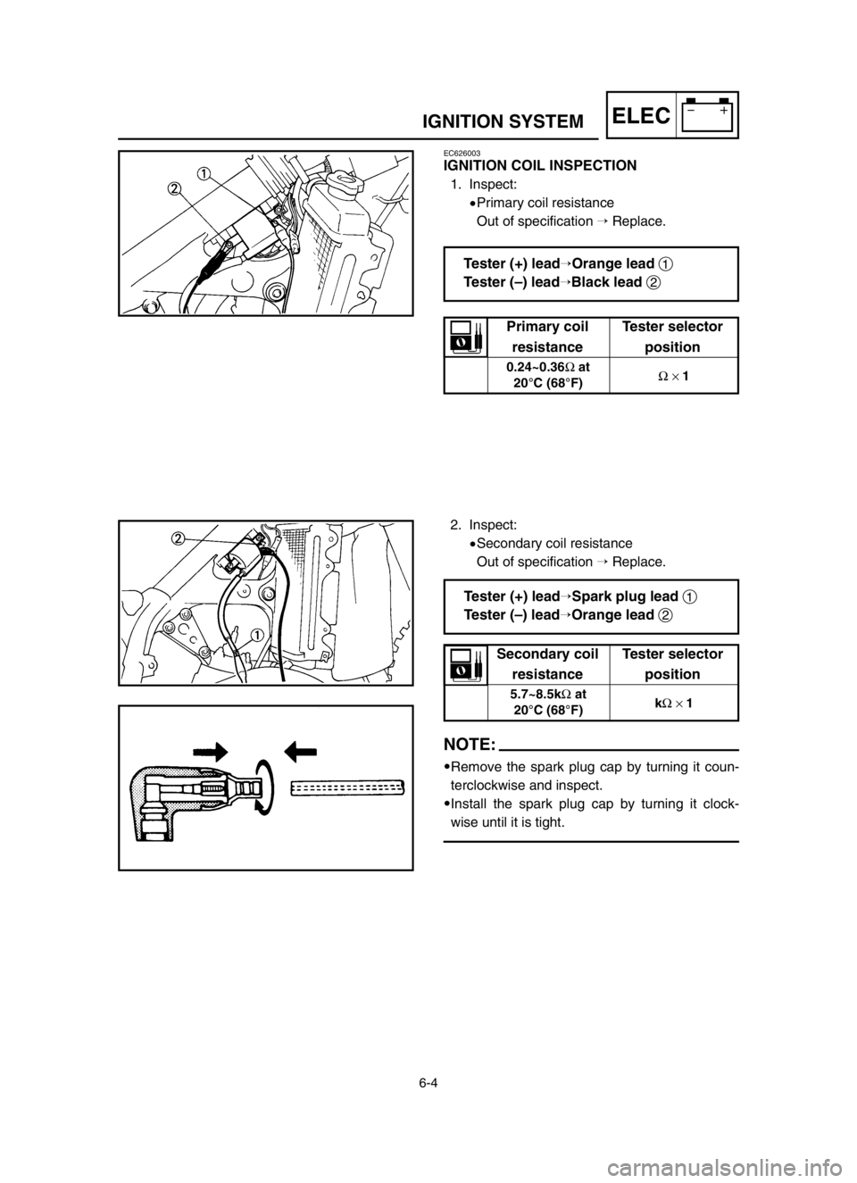
ELECIGNITION SYSTEM
EC626003
IGNITION COIL INSPECTION
1. Inspect:
9Primary coil resistance
Out of specification �Replace.
2. Inspect:
9Secondary coil resistance
Out of specification �Replace.
NOTE:
9Remove the spark plug cap by turning it coun-
terclockwise and inspect.
9Install the spark plug cap by turning it clock-
wise until it is tight.
Tester (+) lead�Orange lead 1
Tester (–) lead
�Black lead 2
Tester (+) lead�Spark plug lead 1
Tester (–) lead
�Orange lead 2
Primary coil Tester selector
resistance position
0.24~0.36Ωat
Ω× 1
20°C (68°F)
Secondary coil Tester selector
resistance position
5.7~8.5kΩat
kΩ× 1
20°C (68°F)
5XE-9-30-6 4/15/03 11:33 AM Page 10
Page 542 of 568
 7-16
TUNSETTING
EC722011
Front fork setting
The front fork setting should be made depending
on the rider’s feeling of an actual run and the cir-
cuit conditions.
The front fork setting includes the")
7-16
TUNSETTING
EC722011
Front fork setting
The front fork setting should be made depending
on the rider’s feeling of an actual run and the cir-
cuit conditions.
The front fork setting includes the following three
factors:
1. Setting of air spring characteristics
9Change the fork oil level.
2. Setting of spring preload
9Change the spring.
9Install the adjustment washer.
3. Setting of damping force
9Change the compression damping.
9Change the rebound damping.
The spring acts on the load and the damp-
ing force acts on the cushion travel speed.
EC723001
Change in level and characteristics of fork oil
Damping characteristic near the final stroke can
be changed by changing the fork oil amount.
cC
Adjust the oil level in 5 mm (0.2 in) incre-
ments or decrements. Too low oil level
causes the front fork to produce a noise at
full rebound or the rider to feel some pres-
sure on his hands or body. Alternatively,
too high oil level will develop unexpectedly
early oil lock with the consequent shorter
front fork travel and deteriorated perfor-
mance an characteristics. Therefore, adjust
the front fork within the specified range.
åAir spring characteristics in relation to oil level
change
∫Load
çStroke
1Max. oil level
2Standard oil level
3Min. oil level
Standard oil level:
125 mm (4.92 in)
Extent of adjustment:
105~135 mm (4.13~5.31 in)
From top of outer tube with
inner tube and damper rod fully
compressed without spring.
A
5XE-9-30-7B 4/28/03 6:01 PM Page 6
 5-32
CHASFRONT FORK
5. Install:
9Spring guide 1
9Locknut 2
To damper rod 3.
NOTE:
9Install the spring guide with its smaller dia. end
afacing downward.
9With its thread bfacing upward, fully finger
ti")

 5-49
CHASSTEERING
4. Install:
9Ring nut 1
Tighten the ring nut using the ring nut
wrench 2.
Refer to “STEERING HEAD INSPECTION
AND ADJUSTMENT” section in the CHAP-
TER 3.
5. Check the steering sha")
 5-59
CHASREAR SHOCK ABSORBER
Extent of removal Order Part name Q’ty Remarks
REAR SHOCK ABSORBER
REMOVAL
Preparation forHold the machine by placing the
removalsuitable stand under the engine.
SeatRef")
 5-63
CHASREAR SHOCK ABSORBER
EC5852B5
Rear shock absorber
1. Install:
9Dust seal 1
9O-ring 2
9Collar 3
NOTE:
9Apply the molybdenum disulfide grease on the
bearing.
9Apply the lithium soap base grease")