Page 266 of 568

4-27
ENGCYLINDER HEAD, CYLINDER AND PISTON
EC475280
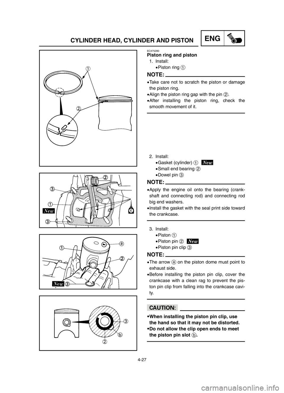
Piston ring and piston
1. Install:
9Piston ring 1
NOTE:
9Take care not to scratch the piston or damage
the piston ring.
9Align the piston ring gap with the pin 2.
9After installing the piston ring, check the
smooth movement of it.
2. Install:
9Gasket (cylinder) 1
9Small end bearing 2
9Dowel pin 3
NOTE:
9Apply the engine oil onto the bearing (crank-
shaft and connecting rod) and connecting rod
big end washers.
9Install the gasket with the seal print side toward
the crankcase.
3. Install:
9Piston 1
9Piston pin 2
9Piston pin clip 3
NOTE:
9The arrow aon the piston dome must point to
exhaust side.
9Before installing the piston pin clip, cover the
crankcase with a clean rag to prevent the pis-
ton pin clip from falling into the crankcase cavi-
ty.
cC
9When installing the piston pin clip, use
the hand so that it may not be distorted.
9Do not allow the clip open ends to meet
the piston pin slot b.
5XE-9-30-4B 3/24/03 11:18 PM Page 20
Page 268 of 568
4-28
ENGCYLINDER HEAD, CYLINDER AND PISTON
3. Install:
9Nut (cylinder) 1
NOTE:
Tighten the nuts in stage, using a crisscross pat-
tern.
4. Install:
9Collar 1
9Push rod 2
9Plain washer 3
9Bolt (push rod) 4
NOTE:
9Set the collar 5included in owner's tool kit to
install the bolt (push rod).
9Do not forget to remove the collar.
EC4753A2
Cylinder head and cylinder
1. Apply:
9Engine oil
To piston 1, piston ring 2and cylinder
surface.
2. Install:
9Cylinder 1
cC
Make sure the piston ring is properly posi-
tioned. Install the cylinder with one hand
while compressing the piston ring with the
other hand.
NOTE:
After installing, check the smooth movement of
the piston.
30 Nm (3.0 m•kg, 22 ft•lb)
5 Nm (0.5 m•kg, 3.6 ft•lb)
5XE-9-30-4B 3/24/03 11:18 PM Page 22
Page 272 of 568
4-30
ENGCLUTCH AND PRIMARY DRIVEN GEAR
Extent of removal Order Part name Q’ty Remarks
CLUTCH PLATE AND
FRICTION PLATE REMOVAL
Preparation for Drain the transmission oil.
Refer to “TRANSMISSION OIL REPLACE-
removalMENT“ section in the CHAPTER 3.
Bolt (brake pedal) Shift the brake pedal downward.
Clutch cable Disconnect at engine side.
1 Clutch cover 1
2 Screw (clutch spring) 5
3 Clutch spring 5
4 Pressure plate 1
5 Push rod 1
6 Plain washer 2
7 Bearing 1
8 Friction plate 8
9 Clutch plate 7
Extent of removal:1Clutch plate and friction plate removal
EC490000
CLUTCH AND PRIMARY DRIVEN GEAREC498000
CLUTCH PLATE AND FRICTION PLATE
1
10 Nm (1.0 m•kg, 7.2 ft•lb)
10 Nm (1.0 m•kg, 7.2 ft•lb)
5XE-9-30-4B 3/24/03 11:18 PM Page 26
Page 288 of 568
4-38
ENG
KICK AXLE, SHIFT SHAFT AND PRIMARY DRIVE
GEAR
Extent of removal Order Part name Q’ty Remarks
RPIMARY DRIVE GEAR REMOVAL
Preparation for Drain the transmission oil.Refer to “TRANSMISSION OIL REPLACE-
removalMENT“ section in the CHAPTER 3.
Clutch cable Disconnect at engine side.
Bolt (brake pedal) Shift the brake pedal downward.
Radiator hose 4 Disconnect at water pump side.
Bolt (push rod)
Refer to “CYLINDER HEAD, CYLINDER
AND PISTON” section.
1 Kick starter 1
2 Crankcase cover (right) 1
3 Bolt (Primary drive gear) 1 Only loosening
Refer to “REMOVAL POINTS”.
4 Primary driven gear 1 Refer to “CLUTCH AND PRIMARY
DRIVEN GEAR”section.
5 Primary drive gear 1
EC4C0000
KICK AXLE, SHIFT SHAFT AND PRIMARY DRIVE GEAREC4C8000PRIMARY DRIVE GEAR
1
Extent of removal:1Primary drive gear removal
10 Nm (1.0 m•kg, 7.2 ft•lb)
10 Nm (1.0 m•kg, 7.2 ft•lb)
55 Nm (5.5 m•kg, 40 ft•lb)
5XE-9-30-4C 4/16/03 10:31 AM Page 2
Page 336 of 568

4-62
ENGCRANKCASE AND CRANKSHAFT
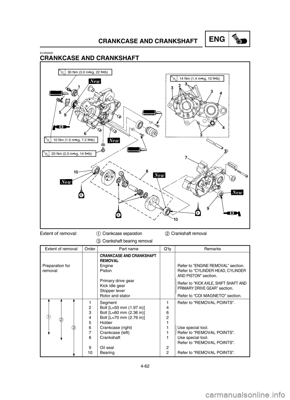
Extent of removal Order Part name Q’ty Remarks
CRANKCASE AND CRANKSHAFT
REMOVAL
Preparation for Engine Refer to “ENGINE REMOVAL”section.
removal Piston Refer to “
CYLINDER HEAD, CYLINDER
AND PISTON
” section.
Primary drive gear
Kick idle gearRefer to “
KICK AXLE, SHIFT SHAFT AND
Stopper leverPRIMARY DRIVE GEAR”section.
Rotor and stator Refer to “CDI MAGNETO” section.
1 Segment 1 Refer to “REMOVAL POINTS”.
2 Bolt [L=50 mm (1.97 in)] 4
3 Bolt [L=60 mm (2.36 in)] 6
4 Bolt [L=70 mm (2.76 in)] 2
5 Holder 1
6 Crankcase (right) 1 Use special tool.
7 Crankcase (left) 1 Refer to “REMOVAL POINTS”.
8 Crankshaft 1 Use special tool.
Refer to “REMOVAL POINTS”.
9 Oil seal 2
10 Bearing 2 Refer to “REMOVAL POINTS”.
EC4N0000
CRANKCASE AND CRANKSHAFT
12
3
Extent of removal:1Crankcase separation2Crankshaft removal
3Crankshaft bearing removal
30 Nm (3.0 m•kg, 22 ft•lb)
10 Nm (1.0 m•kg, 7.2 ft•lb)
20 Nm (2.0 m•kg, 14 ft•lb)
14 Nm (1.4 m•kg, 10 ft•lb)
5XE-9-30-4D 3/24/03 11:14 PM Page 12
Page 348 of 568
4-68
ENGCRANKCASE AND CRANKSHAFT
6. Install:
9Holder 1
9Bolt (holder) 2
7. Install:
9Segment 1
9Bolt (segment) 2
NOTE:
9When installing the segment onto the shift cam
3, align the punch mark awith the dowel pin
b.
9Turn the segment clockwise until it stops and
tighten the bolt.
8. Remove:
9Sealant
Forced out on the cylinder mating surface.
9. Apply:
9Engine oil
To the crank pin, bearing, oil delivery hole
and connecting rod big end washer.
10. Check:
9Crankshaft and transmission operation
Unsmooth operation �Repair.
30 Nm (3.0 m•kg, 22 ft•lb)
10 Nm (1.0 m•kg, 7.2 ft•lb)
5XE-9-30-4D 3/24/03 11:14 PM Page 24
Page 362 of 568
5-1
CHASFRONT WHEEL AND REAR WHEEL
Extent of removal Order Part name Q’ty Remarks
FRONT WHEEL REMOVAL
Preparation for
Hold the machine by placing the
removalsuitable stand under the engine.
1 Hose cover 1
2 Bolt (brake hose holder) 2 Only loosening.
3 Bolt (axle holder) 4 Only loosening.
4 Nut (front wheel axle) 1
5 Front wheel axle 1
6 Front wheel 1
7 Collar 2
8 Oil seal 2
9 Bearing 2 Refer to “REMOVAL POINTS”.
10 Brake disc 1
EC500000
CHASSISEC590000
FRONT WHEEL AND REAR WHEELEC598000
FRONT WHEEL
2
13
3
Extent of removal:1Front wheel removal2Wheel bearing removal3Brake disc removal
w
Support the machine securely so there is no dan-
ger of it falling over.
23 Nm (2.3 m•kg, 17 ft•lb)
23 Nm (2.3 m•kg, 17 ft•lb)
105 Nm (10.5 m•kg, 75 ft•lb)
16 Nm (1.6 m•kg, 11 ft•lb)
7 Nm (0.7 m•kg, 5.1 ft•lb)12 Nm (1.2 m•kg, 8.7 ft•lb)
10 Nm (1.0 m•kg, 7.2 ft•lb)
5XE-9-30-5A 4/28/03 6:06 PM Page 2
Page 364 of 568
5-2
CHASFRONT WHEEL AND REAR WHEEL
EC598100
REAR WHEEL
Extent of removal:1Rear wheel removal2Wheel bearing removal3Brake disc removal
Extent of removal Order Part name Q’ty Remarks
REAR WHEEL REMOVAL
Preparation for
Hold the machine by placing the
removalsuitable stand under the engine.
1 Nut (rear wheel axle) 1
2 Rear wheel axle 1
3 Chain puller 2
4 Rear wheel 1 Refer to “REMOVAL POINTS”.
5 Collar 2
6 Driven sprocket 1
7 Oil seal 2
8 Circlip 1
9 Bearing 2 Refer to “REMOVAL POINTS”.
10 Brake disc 1
2
13
3
w
Support the machine securely so there is no dan-
ger of it falling over.
125 Nm (12.5 m•kg, 90 ft•lb)
14 Nm (1.4 m•kg, 10 ft•lb)
16 Nm (1.6 m•kg, 11 ft•lb)
16 Nm (1.6 m•kg, 11 ft•lb)
42 Nm (4.2 m•kg, 30 ft•lb)
5XE-9-30-5A 4/28/03 6:06 PM Page 4