Page 468 of 568
 5-54
CHASSWINGARM
EC575000
ASSEMBLY AND INSTALLATION
EC575202
Bearing and oil seal
1. Install:
9Bearing 1
9Oil seal 2
To swingarm.
NOTE:
9Apply the molybdenum disulfide grease on the
bearing when inst")
5-54
CHASSWINGARM
EC575000
ASSEMBLY AND INSTALLATION
EC575202
Bearing and oil seal
1. Install:
9Bearing 1
9Oil seal 2
To swingarm.
NOTE:
9Apply the molybdenum disulfide grease on the
bearing when installing.
9Install the bearing by pressing it on the side hav-
ing the manufacture's marks or numbers.
9First install the outer and then the inner bear-
ings to a specified depth from inside.
Installed depth of bearings:
Outer a a
: Zero mm (Zero in)
Inner b b
: 8.5 mm (0.33 in)
EC574311
Connecting rod
1. Inspect:
9Bearing (polylube bearing) 1
9Collar 2
Free play exists/Unsmooth revolution/Rust �
Replace bearing and collar as a set.
2. Inspect:
9Bearing (polylube bearing) 1
Loss of solid lubrication �Replace.
9Oil seal 3
Damage �Replace.
NOTE:
Polylube bearings, with solid lubrication, have
been adopted with the intent to make the needle
bearings, used in this model, maintenance free.
With polylube bearings, no grease nipple and
regular lubrication is necessary. However,
grease should be applied to all oil seals and col-
lars when removed or installed.
5XE-9-30-5D 4/28/03 6:02 PM Page 8
Page 470 of 568
5-55
CHASSWINGARM
EC5751B3
Swingarm
1. Install:
9Bush 1
9Thrust bearing 2
9Oil seal 3
9Collar 4
To swingarm 5.
NOTE:
Apply the molybdenum disulfide grease on the
bushes, thrust bearings and oil seal lips.
2. Install:
9Collar 1
To relay arm 2.
NOTE:
Apply the molybdenum disulfide grease on the
collars and oil seal lips.
3. Install:
9Bearing 1
9Oil seal 2
To connecting rod.
NOTE:
9Apply the molybdenum disulfide grease on the
bearing when installing.
9Install the bearing by pressing it on the side hav-
ing the manufacture's marks or numbers.
Installed depth of bearings a a
:
5 mm (0.20 in)
2. Install:
9Bearing 1
9Oil seal 2
To relay arm.
NOTE:
9Apply the molybdenum disulfide grease on the
bearing when installing.
9Install the bearing by pressing it on the side hav-
ing the manufacture's marks or numbers.
Installed depth of bearings a a
:
5 mm (0.20 in)
5XE-9-30-5D 4/28/03 6:02 PM Page 10
Page 472 of 568
5-56
CHASSWINGARM
5. Install:
9Relay arm 1
9Bolt (relay arm) 2
9Plain washer 3
9Nut (relay arm) 4
To swingarm.
NOTE:
9Apply the molybdenum disulfide grease on the
bolt.
9Do not tighten the nut yet.
6. Install:
9Swingarm 1
9Pivot shaft 2
NOTE:
9Apply the molybdenum disulfide grease on the
pivot shaft.
9Insert the pivot shaft from right side.
85 Nm (8.5 m•kg, 61 ft•lb)
4. Install:
9Connecting rod 1
9Bolt (connecting rod) 2
9Plain washer 3
9Nut (connecting rod) 4
To relay arm 5.
NOTE:
Apply the molybdenum disulfide grease on the
bolt.
80 Nm (8.0 m•kg, 58 ft•lb)
3. Install:
9Collar 1
To connecting rod 2.
NOTE:
Apply the molybdenum disulfide grease on the
collar and oil seal lips.
5XE-9-30-5D 4/28/03 6:02 PM Page 12
Page 480 of 568
 5-60
CHASREAR SHOCK ABSORBER
EC586000
HANDLING NOTE
w
This shock absorber is provided with a
separate type tank filled with high-pressure
nitrogen gas. To prevent the danger of ex-
plosion, read and u")
5-60
CHASREAR SHOCK ABSORBER
EC586000
HANDLING NOTE
w
This shock absorber is provided with a
separate type tank filled with high-pressure
nitrogen gas. To prevent the danger of ex-
plosion, read and understand the following
information before handling the shock ab-
sorber.
The manufacturer can not be held respon-
sible for property damage or personal in-
jury that may result from improper han-
dling.
1. Never tamper or attempt to disassemble
the cylinder or the tank.
2. Never throw the shock absorber into an
open flame or other high heat. The shock
absorber may explode as a result of ni-
trogen gas expansion and/or damage to
the hose.
3. Be careful not to damage any part of the
gas tank. A damaged gas tank will impair
the damping performance or cause a
malfunction.
4. Take care not to scratch the contact sur-
face of the piston rod with the cylinder;
or oil could leak out.
5. Never attempt to remove the plug at the
bottom of the nitrogen gas tank. It is very
dangerous to remove the plug.
6. When scrapping the shock absorber, fol-
low the instructions on disposal.
EC587000
NOTES ON DISPOSAL (YAMAHA DEAL-
ERS ONLY)
Before disposing the shock absorber, be sure to
extract the nitrogen gas from valve 1. Wear eye
protection to prevent eye damage from escaping
gas and/or metal chips.
w
To dispose of a damaged or worn-out
shock absorber, take the unit to your
Yamaha dealer for this disposal procedure.
5XE-9-30-5D 4/28/03 6:02 PM Page 20
Page 482 of 568
5-61
CHASREAR SHOCK ABSORBER
EC583000
REMOVAL POINTS
EC583320
Bearing
1. Remove:
9Stopper ring (upper bearing) 1
NOTE:
Press in the bearing while pressing its outer race
and remove the stopper ring.
2. Remove:
9Upper bearing 1
NOTE:
Remove the bearing by pressing its outer race.
EC584000
INSPECTION
EC584110
Rear shock absorber
1. Inspect:
9Damper rod 1
Bends/Damage �Replace absorber
assembly.
9Shock absorber 2
Oil leaks �Replace absorber assembly.
Gas leaks �Replace absorber assembly.
9Spring 3
Damage �Replace spring.
Fatigue �Replace spring.
Move spring up and down.
9Spring guide 4
Wear/Damage �Replace spring guide.
9Bearing 5
Free play exists/Unsmooth revolution/
Rust �Replace. 3. Remove:
9Lower bearing 1
NOTE:
Remove the bearing by pressing its outer race.
5XE-9-30-5D 4/28/03 6:02 PM Page 22
Page 490 of 568
6-1
ELECELECTRICAL COMPONENTS AND WIRING DIAGRAM
EC600000
ELECTRICAL
EC610000
ELECTRICAL COMPONENTS AND WIRING DIAGRAM
EC611000
ELECTRICAL COMPONENTS
1“ENGINE STOP” button
2Ignition coil
3CDI unit
4CDI magneto
5Spark plug
EC612000
WIRING DIAGRAM
COLOR CODE
B...................Black
O ..................Orange
B/R ...............Brack/Red
B/W ..............Black/White
G/L ..............Green/Blue
G/W ..............Green/White
W/L...............White/Blue
W/R ..............White/Red
G/W
G/WB/W
BB/W
B
B
G/L
B/R
G/W
W/R
W/L
B O W/L
W/R
BW/R W/L
B
B/RG/L G/L B/R
B/W O O B/WG/L
BB/R
G/WW/L
W/RW/L
W/RB/R
G/WG/L
B
5XE-9-30-6 4/15/03 11:33 AM Page 2
Page 492 of 568
6-2
ELECIGNITION SYSTEM
EC620000
IGNITION SYSTEM
EC621003
INSPECTION STEPS
Use the following steps for checking the possibility of the malfunctioning engine being attributable to
ignition system failure and for checking the spark plug which will not spark.
*Clean or replace
spark plug.
Primary coil
Secondary coil
Repair or replace.
Spark
Check entire ignition
system for connection.
Spark gap test
No good
No good
No good
No good
No good
No good No Spark
Check “ENGINE STOP”
button.
Pick-up coil
Source coil
Check ignition coil.
Check CDI magneto.
Replace CDI unit.
Replace.
Replace.
Replace.
Replace.
Replace.
*marked: Only when the ignition checker is used.
NOTE:
9Remove the following parts before inspection.
1) Seat
2) Fuel tank
9Use the following special tools in this inspection.
Dynamic spark tester:
YM-34487
Ignition checker:
90890-06754Pocket tester:
YU-3112-C/90890-03112
OK
OK
OK
OKReplace.
Check spark plug cap.No good
OK
5XE-9-30-6 4/15/03 11:33 AM Page 4
Page 498 of 568
6-4
ELECIGNITION SYSTEM
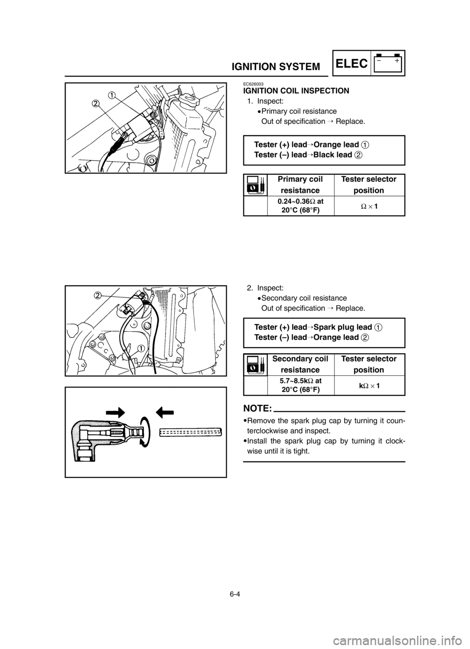
EC626003
IGNITION COIL INSPECTION
1. Inspect:
9Primary coil resistance
Out of specification �Replace.
2. Inspect:
9Secondary coil resistance
Out of specification �Replace.
NOTE:
9Remove the spark plug cap by turning it coun-
terclockwise and inspect.
9Install the spark plug cap by turning it clock-
wise until it is tight.
Tester (+) lead�Orange lead 1
Tester (–) lead
�Black lead 2
Tester (+) lead�Spark plug lead 1
Tester (–) lead
�Orange lead 2
Primary coil Tester selector
resistance position
0.24~0.36Ωat
Ω× 1
20°C (68°F)
Secondary coil Tester selector
resistance position
5.7~8.5kΩat
kΩ× 1
20°C (68°F)
5XE-9-30-6 4/15/03 11:33 AM Page 10
 5-55
CHASSWINGARM
EC5751B3
Swingarm
1. Install:
9Bush 1
9Thrust bearing 2
9Oil seal 3
9Collar 4
To swingarm 5.
NOTE:
Apply the molybdenum disulfide grease on the
bushes, thrust bearings and oil seal l")
 5-56
CHASSWINGARM
5. Install:
9Relay arm 1
9Bolt (relay arm) 2
9Plain washer 3
9Nut (relay arm) 4
To swingarm.
NOTE:
9Apply the molybdenum disulfide grease on the
bolt.
9Do not tighten the nut yet.
6.")
 5-61
CHASREAR SHOCK ABSORBER
EC583000
REMOVAL POINTS
EC583320
Bearing
1. Remove:
9Stopper ring (upper bearing) 1
NOTE:
Press in the bearing while pressing its outer race
and remove the stopper ring.
2")
 6-1
ELECELECTRICAL COMPONENTS AND WIRING DIAGRAM
EC600000
ELECTRICAL
EC610000
ELECTRICAL COMPONENTS AND WIRING DIAGRAM
EC611000
ELECTRICAL COMPONENTS
1“ENGINE STOP” button
2Ignition coil
3CDI unit")
 6-2
ELECIGNITION SYSTEM
EC620000
IGNITION SYSTEM
EC621003
INSPECTION STEPS
Use the following steps for checking the possibility of the malfunctioning engine being attributable to
ignition system failu")