Page 142 of 568

3-5
INSP
ADJENGINE/COOLANT LEVEL INSPECTION/
COOLANT REPLACEMENT
EC350000
ENGINE
EC351011
COOLANT LEVEL INSPECTION
w
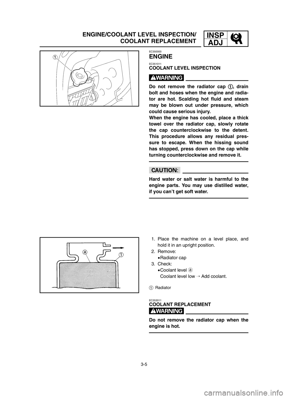
Do not remove the radiator cap 1 1
, drain
bolt and hoses when the engine and radia-
tor are hot. Scalding hot fluid and steam
may be blown out under pressure, which
could cause serious injury.
When the engine has cooled, place a thick
towel over the radiator cap, slowly rotate
the cap counterclockwise to the detent.
This procedure allows any residual pres-
sure to escape. When the hissing sound
has stopped, press down on the cap while
turning counterclockwise and remove it.
cC
Hard water or salt water is harmful to the
engine parts. You may use distilled water,
if you can’t get soft water.
1. Place the machine on a level place, and
hold it in an upright position.
2. Remove:
9Radiator cap
3. Check:
9Coolant level a
Coolant level low �Add coolant.
1Radiator
EC353011
COOLANT REPLACEMENT
w
Do not remove the radiator cap when the
engine is hot.
5XE-9-30-3A 4/28/03 5:55 PM Page 18
Page 184 of 568

3-26
FRONT FORK INSPECTION
INSP
ADJ
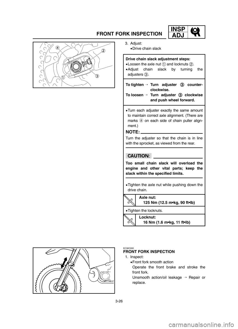
3. Adjust:
9Drive chain slack
EC36C000
FRONT FORK INSPECTION
1. Inspect:
9Front fork smooth action
Operate the front brake and stroke the
front fork.
Unsmooth action/oil leakage �Repair or
replace.
Drive chain slack adjustment steps:
9Loosen the axle nut 1and locknuts 2.
9Adjust chain slack by turning the
adjusters 3.
To tighten �Turn adjuster 3 3
counter-
clockwise.
To loosen �Turn adjuster 3 3
clockwise
and push wheel forward.
9Turn each adjuster exactly the same amount
to maintain correct axle alignment. (There are
marks aon each side of chain puller align-
ment.)
NOTE:
Turn the adjuster so that the chain is in line
with the sprocket, as viewed from the rear.
cC
Too small chain slack will overload the
engine and other vital parts; keep the
slack within the specified limits.
9Tighten the axle nut while pushing down the
drive chain.
9Tighten the locknuts.
Axle nut:
125 Nm (12.5 m•kg, 90 ft•lb)
Locknut:
16 Nm (1.6 m•kg, 11 ft•lb)
5XE-9-30-3B 4/16/03 10:24 AM Page 16
Page 210 of 568
3-39
IGNITION TIMING CHECK
INSP
ADJ
EC372012
IGNITION TIMING CHECK
1. Remove:
9Fuel tank
Refer to “SEAT, FUEL TANK AND SIDE
COVERS” section in the CHAPTER 4.
9Spark plug
9Crankcase cover (left)
2. Attach:
9Dial gauge 1
9Spark plug hole dial stand 2
3. Rotate the magneto rotor 1until the
piston reaches top dead center (TDC).
When this happens, the needle on the dial
gauge will stop and reverse directions even
though the rotor is being turned in the same
direction.
4. Set the dial gauge to zero at TDC.
5. From TDC, rotate the rotor clockwise
until the dial gauge indicates that the
piston is at a specified distance from TDC.
6. Check:
9Ignition timing
Punch mark aon rotor should be aligned
with punch mark bon stator.
Not aligned �Adjust.
Dial gauge:
YU-3097/90890-01252
Spark plug hole dial stand:
YU-1256
Ignition timing (B.T.D.C.):
0.52 mm (0.020 in)
5XE-9-30-3B 4/16/03 10:24 AM Page 42
Page 222 of 568
4-5
ENGRADIATOR
EC456000
HANDLING NOTE
w
Do not remove the radiator cap when the
engine and radiator are hot. Scalding hot
fluid and steam may be blown out under
pressure, which could cause serious in-
jury.
When the engine has cooled, open the ra-
diator cap by the following procedure:
Place a thick rag, like a towel, over the
radiator cap, slowly rotate the cap counter-
clockwise to the detent. This procedure al-
lows any residual pressure to escape.
When the hissing sound has stopped,
press down on the cap while turning coun-
terclockwise and remove it.
EC454000
INSPECTION
EC444100
Radiator
1. Inspect:
9Radiator core 1
Obstruction �Blow out with compressed air
through rear of the radiator.
Bent fin �Repair/replace.
5XE-9-30-4A 4/28/03 6:09 PM Page 10
Page 300 of 568
4-44
ENG
KICK AXLE, SHIFT SHAFT AND PRIMARY DRIVE
GEAR
4. Hook:
9Torsion spring 1
NOTE:
Turn the torsion spring clockwise and hook into
the proper hole ain the crankcase.
EC4C5402
Kick idle gear
1. Install:
9Circlip 1
9Kick idle gear 2
9Plain washer 3
NOTE:
9Apply the transmission oil on the kick idle gear
inner circumference.
9Install the kick idle gear with its depressed side
atoward you.
EC4C5503
Primary drive gear
1. Install:
9Spacer 1
9Primary drive gear 2
9Bolt 3
NOTE:
Temporarily tighten the bolt at this point.
2. Install:
9Primary driven gear
Refer to “CLUTCH AND PRIMARY DRI-
VEN GEAR” section.
3. Tighten:
9Bolt (primary drive gear) 1
NOTE:
Place an aluminum plate abetween the teeth of
the primary drive gear 2and driven gear 3.
4. Install:
9Dowel pin 1
9Gasket [crankcase cover (right)] 2
55 Nm (5.5 m•kg, 40 ft•lb)
5XE-9-30-4C 4/16/03 10:31 AM Page 14
Page 320 of 568
4-54
ENGCDI MAGNETO
EC4L3000
REMOVAL POINTS
EC4L3102
Rotor
1. Remove:
9Nut (rotor) 1
9Plain washer 2
Use the rotor holding tool 3.
2. Remove:
9Rotor 1
Use the flywheel puller 2.
NOTE:
When installing the flywheel puller, turn it coun-
terclockwise.
EC4L4000
INSPECTION
EC4L4101
CDI magneto
1. Inspect:
9Rotor inner surface a
9Stator outer surface b
Damage �Inspect the crankshaft runout
and crankshaft bearing.
If necessary, replace CDI magneto and/or
stator.
EC4L4200
Woodruff key
1. Inspect:
9Woodruff key 1
Damage �Replace.
EC4L5000
ASSEMBLY AND INSTALLATION
EC4L5172
CDI magneto
1. Install:
9Stator 1
9Screw (stator) 2
NOTE:
Temporarily tighten the screw (stator) at this
point.
Rotor holding tool:
YU-1235/90890-01235
Flywheel puller:
YM-1189/90890-01189
5XE-9-30-4C 4/16/03 10:32 AM Page 34
Page 338 of 568

4-63
ENGCRANKCASE AND CRANKSHAFT
EC4N3000
REMOVAL POINTS
EC4N3100
Segment
1. Remove:
9Bolt (segment) 1
9Segment 2
NOTE:
Turn the segment counterclockwise until it stops
and loosen the bolt.
EC4N3212
Crankcase
1. Remove:
9Crankcase (right) 1
Use the crankcase separating tool 2.
NOTE:
9Make appropriate bolts 3as shown available
by yourself and attach the tool with them.
9Fully tighten the tool holding bolts, but make
sure the tool body is parallel with the case. If
necessary, one screw may be backed out
slightly to level tool body.
9As pressure is applied, alternately tap on the
front engine mounting boss and transmission
shafts.
cC
Use soft hammer to tap on the case half.
Tap only on reinforced portions of case. Do
not tap on gasket mating surface. Work
slowly and carefully. Make sure the case
halves separate evenly. If one end “hangs
up”, take pressure off the push screw, re-
align, and start over. If the cases do not
separate, check for a remaining case
screw or fitting. Do not force.
Crankcase separating tool:
YU-1135-A/90890-01135
5XE-9-30-4D 3/24/03 11:14 PM Page 14
Page 348 of 568
4-68
ENGCRANKCASE AND CRANKSHAFT
6. Install:
9Holder 1
9Bolt (holder) 2
7. Install:
9Segment 1
9Bolt (segment) 2
NOTE:
9When installing the segment onto the shift cam
3, align the punch mark awith the dowel pin
b.
9Turn the segment clockwise until it stops and
tighten the bolt.
8. Remove:
9Sealant
Forced out on the cylinder mating surface.
9. Apply:
9Engine oil
To the crank pin, bearing, oil delivery hole
and connecting rod big end washer.
10. Check:
9Crankshaft and transmission operation
Unsmooth operation �Repair.
30 Nm (3.0 m•kg, 22 ft•lb)
10 Nm (1.0 m•kg, 7.2 ft•lb)
5XE-9-30-4D 3/24/03 11:14 PM Page 24