Page 302 of 754
4 - 1
ENG
EC400000
ENGINE
EC4R0000
SEAT, FUEL TANK AND SIDE COVERS
Extent of removal:
1
Seat removal
2
Fuel tank removal
3
Side covers removal
4
Headlight removal
Extent of removal Order Part name Q’ty Remarks
Preparation for removal
SEAT, FUEL TANK AND SIDE
COVERS REMOVAL
Turn the fuel cock to “OFF”.
Disconnect the fuel hose.
1 Seat 1
2 Air scoop (left and right) 2
3 Fitting band 1 Remove on fuel tank side.
4 Bolt (fuel tank) 2
5 Fuel tank 1
6 Side cover (left) 1
Refer to “REMOVAL POINTS”.
7 Side cover (right) 1
8 Headlight coupler 1
9 Headlight 1
13
2
3
4
SEAT, FUEL TANK AND SIDE COVERS
Page 310 of 754
4 - 5
ENG
RADIATOR
EC450001
RADIATOR
Extent of removal:
1
Radiator removal
2
Coolant reservoir removal
Extent of removal Order Part name Q’ty Remarks
RADIATOR REMOVAL
Preparation for removal Drain the coolant. Refer to “COOLANT REPLACEMENT”
section in the CHAPTER 3.
Seat, fuel tank and side cover Refer to “SEAT, FUEL TANK AND SIDE
COVERS” section.
Exhaust pipe Refer to “EXHAUST PIPE AND
SILENCER” section.
1 Engine guard 1
2 Panel 2
3 Clamp 8
4 Radiator (right) 1
5 Hose 2 1
6 Hose 3 1
7 Hose 4 1
8 Pipe 2/O-ring 1/1
9 Radiator breather hose 1
10 Radiator (left) 1
11 Hose 1 1
12 Pipe 1/O-ring 1/1
13 Coolant reservoir hose 1
14 Coolant reservoir tank 1
1
2
Page 312 of 754

4 - 6
ENGRADIATOR
EC456000
HANDLING NOTE
WARNING
Do not remove the radiator cap when the
engine and radiator are hot. Scalding hot
fluid and steam may be blown out under
pressure, which could cause serious
injury.
When the engine has cooled, open the radi-
ator cap by the following procedure:
Place a thick rag, like a towel, over the radi-
ator cap, slowly rotate the cap counter-
clockwise to the detent. This procedure
allows any residual pressure to escape.
When the hissing sound has stopped,
press down on the cap while turning coun-
terclockwise and remove it.
EC454000
INSPECTION
EC444100
Radiator
1. Inspect:
�Radiator core 1
Obstruction → Blow out with com-
pressed air through rear of the radiator.
Bent fin → Repair/replace.
EC455000
ASSEMBLY AND INSTALLATION
Radiator
1. Install:
�Pipe 1 1
�Hose 1 2
�Pipe 2 3
�Hose 3 4
�Hose 4 5
2. Install:
�Hose 2 1
�Radiator (left) 2
T R..10 Nm (1.0 m · kg, 7.2 ft · lb)
T R..2 Nm (0.2 m · kg, 1.4 ft · lb)
T R..10 Nm (1.0 m · kg, 7.2 ft · lb)
T R..2 Nm (0.2 m · kg, 1.4 ft · lb)
T R..2 Nm (0.2 m · kg, 1.4 ft · lb)
T R..2 Nm (0.2 m · kg, 1.4 ft · lb)
T R..10 Nm (1.0 m · kg, 7.2 ft · lb)
Page 322 of 754
} 1 except when changing
the TPS (throttle position sensor) due to
failure because it will")
4 - 11
ENGCARBURETOR
EC466020
HANDLING NOTE
CAUTION:
Do not loosen the screws {TPS (throttle
position sensor)} 1 except when changing
the TPS (throttle position sensor) due to
failure because it will cause a drop in
engine performance.
1
REMOVAL POINTS
Pilot screw
1. Remove:
�Pilot screw 1
NOTE:
To optimize the fuel flow at a small throttle
opening, each machine’s pilot screw has been
individually set at the factory. Before removing
the pilot screw, turn it in fully and count the
number of turns. Record this number as the
factory-set number of turns out.
INSPECTION
Carburetor
1. Inspect:
�Carburetor body
Contamination → Clean.
NOTE:
�Use a petroleum based solvent for cleaning.
Blow out all passages and jets with com-
pressed air.
�Never use a wire.
2. Inspect:
�Main jet 1
�Pilot jet 2
�Needle jet 3
�Starter jet 4
�Pilot air jet 5
�Leak jet 6
Damage → Replace.
Contamination → Clean.
NOTE:
�Use a petroleum based solvent for cleaning.
Blow out all passages and jets with com-
pressed air.
�Never use a wire.
Page 342 of 754
4 - 21
ENGCAMSHAFTS
CAMSHAFTS
CYLINDER HEAD COVER
Extent of removal:1 Cylinder head cover removal
Extent of removal Order Part name Q’ty Remarks
CYLINDER HEAD COVER
REMOVAL
Preparation for removal Seat and fuel tank Refer to “SEAT, FUEL TANK AND SIDE
COVERS” section.
Carburetor Refer to “CARBURETOR” section.
1 Spark plug 1
2 Engine upper bracket (right) 1
3 Engine upper bracket (left) 1
4 Cylinder head breather hose 1
5 Oil tank breather hose 1
6 Bolt (cylinder head cover) 2
7 Cylinder head cover 1
8 Gasket 1
9 Timing chain guide (upper) 1
1
Page 352 of 754
4 - 26
ENGCAMSHAFTS
Decompression system
1. Check:
�Decompression system
Checking steps:
�Check that the decompressor cam 1
moves smoothly.
�Check that the decompressor lever pin 2
projects from the camshaft.
Timing chain tensioner
1. Check:
�While pressing the tensioner rod lightly
with fingers, use a thin screwdriver 1
and wind the tensioner rod up fully
clockwise.
�When releasing the screwdriver by
pressing lightly with fingers, make sure
that the tensioner rod will come out
smoothly.
�If not, replace the tensioner assembly.
ASSEMBLY AND INSTALLATION
1. Install:
�Exhaust camshaft 1
�Intake camshaft 2
Installation steps:
�Turn the crankshaft counterclockwise until
the “I” mark a on the rotor is aligned with
the stationary pointer b on the crankcase
cover.
NOTE:
�Apply the molybdenum disulfide oil on the
camshafts.
�Apply the engine oil on the decompression
system.
Page 354 of 754

4 - 27
ENGCAMSHAFTS
�Fit the timing chain 3 onto both camshaft
sprockets and install the camshafts on the
cylinder head.
NOTE:
The camshafts should be installed onto the
cylinder head so that the exhaust cam
sprocket punch mark c and the intake cam
sprocket punch mark d align with the sur-
face of the cylinder head.
CAUTION:
Do not turn the crankshaft during the
camshaft installation. Damage or
improper valve timing will result.
�Install the clips and camshaft caps 4.
T R..
Bolt (camshaft cap):
10 Nm (1.0 m • kg, 7.2 ft • lb)
NOTE:
�Apply the engine oil on the thread and con-
tact surface of the bolts (camshaft cap) 5.
�Tighten the bolts (camshaft cap) in a criss-
cross pattern.
CAUTION:
The bolts (camshaft cap) must be tight-
ened evenly, or damage to the cylinder
head, camshaft caps, and camshaft will
result.
5
4
E
2. Install:
�Timing chain tensioner
Installation steps:
�While pressing the tensioner rod lightly
with fingers, use a thin screwdriver and
wind the tensioner rod up fully clockwise.
Page 382 of 754
4 - 41
ENGVALVES AND VALVE SPRINGS
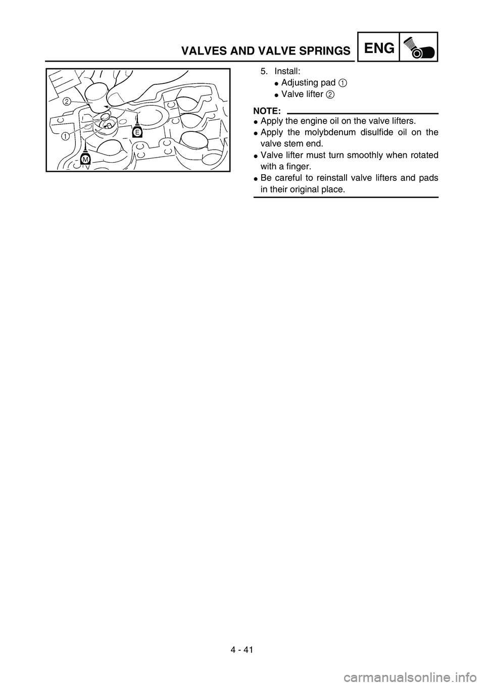
5. Install:
�Adjusting pad 1
�Valve lifter 2
NOTE:
�Apply the engine oil on the valve lifters.
�Apply the molybdenum disulfide oil on the
valve stem end.
�Valve lifter must turn smoothly when rotated
with a finger.
�Be careful to reinstall valve lifters and pads
in their original place.