Page 160 of 754

2 - 23
SPEC
CABLE ROUTING DIAGRAM
EC240000
CABLE ROUTING DIAGRAM
1
Fuel tank breather hose
2
Clamp
3
Diode
4
Wire harness
5
Hot starter cable
6
Negative battery lead
7
Starter moto")
2 - 23
SPEC
CABLE ROUTING DIAGRAM
EC240000
CABLE ROUTING DIAGRAM
1
Fuel tank breather hose
2
Clamp
3
Diode
4
Wire harness
5
Hot starter cable
6
Negative battery lead
7
Starter motor lead
8
TPS (throttle position sen-
sor) lead
9
Neutral switch lead
0
Oil hose
A
Hose holder
B
Radiator hose 4
C
Cylinder head breather hose
D
AC magneto lead
E
Radiator hose 1
F
Oil tank breather hose
G
Brake hose
H
Hose guide
I
Carburetor breather hose
J
Overflow hose
K
Coolant reservoir tank breather
hose
Å
Insert the fuel tank breather
hose into the hole in the steering
shaft cap.
ı
Fasten the diode of the wire har-
ness and rectifier/regulator lead
(at its protecting tube) to the
frame at the white tape for the
diode with a plastic locking tie
and cut off the tie end.
Ç
Fasten the wire harness, recti-
fier/regulator lead, coolant res-
ervoir hose and hot starter cable
to the frame with a plastic lock-
ing tie and cut off the tie end.
Î
Fasten the wire harness, recti-
fier/regulator lead and coolant
reservoir hose to the frame with
a plastic locking tie and cut off
the tie end.
‰
Fasten the wire harness to the
frame at its white tape with a
plastic locking tie and cut off the
tie end.
Page 173 of 754

3 - 2
INSP
ADJ
MAINTENANCE INTERVALS
SHIFT FORK, SHIFT CAM, GUIDE BAR
Inspect
●
Inspect wear
ROTOR NUT
Retighten
●
●
MUFFLER
Inspect and retighten
Clean
Replace
●
●")
3 - 2
INSP
ADJ
MAINTENANCE INTERVALS
SHIFT FORK, SHIFT CAM, GUIDE BAR
Inspect
●
Inspect wear
ROTOR NUT
Retighten
●
●
MUFFLER
Inspect and retighten
Clean
Replace
●
●
●
●
* Whichever comes first
*SPARK ARRESTER
Clean
(Every
six
months)
●
CRANK
Inspect and clean
●
●
CARBURETOR
Inspect, adjust and clean
●
●
SPARK PLUG
Inspect and clean
Replace
●
●
●
DRIVE CHAIN
Lubricate, slack, alignment
Replace
●
●
●
Use chain lube
Chain slack: 40 ~ 50 mm
(1.57 ~ 1.97 in)
COOLING SYSTEM
Check coolant level and leakage
Check radiator cap operation
Replace coolant
Inspect hoses
●
●
●
●
●
Every two years
OUTSIDE NUTS AND BOLTS
Retighten
●
●
Refer to “STARTING
AND BREAK-IN” section
in the CHAPTER 1.
AIR FILTER
Clean and lubricate
Replace
●
●
●
Use foam air-filter oil or
equivalent oil
OIL FILTER
Replace
●
●
OIL STRAINER (frame)
Clean
●
FRAME
Clean and inspect
●
●
FUEL TANK, COCK
Clean and inspect
●
●
BRAKES
Adjust lever position and pedal height
Lubricate pivot point
Check brake disc surface
Check fluid level and leakage
Retighten brake disc bolts, caliper
bolts, master cylinder bolts and union
bolts
Replace pads
Replace brake fluid
●
●
●
●
●
●
●
●
●
●
●
●
Every one year ItemAfter
break-inEvery
race
Every
third
(or
500 km)Every
fifth
(or
1,000 km)
As re-
quiredRemarks
3
Page 184 of 754
 3 - 4
INSP
ADJ
PRE-OPERATION INSPECTION AND MAINTENANCE
EC320000
PRE-OPERATION INSPECTION AND MAINTENANCE
Before riding for break-in operation, practice or a race, make sure the machine is in good ope")
3 - 4
INSP
ADJ
PRE-OPERATION INSPECTION AND MAINTENANCE
EC320000
PRE-OPERATION INSPECTION AND MAINTENANCE
Before riding for break-in operation, practice or a race, make sure the machine is in good operating
condition.
Before using this machine, check the following points.
GENERAL INSPECTION AND MAINTENANCE
Item Routine Page
CoolantCheck that coolant is filled up to the radiator filler cap.
Check the cooling system for leakage.P.3-5 ~ 9
FuelCheck that a fresh gasoline is filled in the fuel tank. Check the
fuel line for leakage.P.1-14
Engine oilCheck that the oil level is correct. Check the crankcase and
frame oil line for leakage.P.3-14 ~ 18
Gear shifter and clutchCheck that gears can be shifted correctly in order and that the
clutch operates smoothly.P.3-10
Throttle grip/HousingCheck that the throttle grip operation and free play are correctly
adjusted. Lubricate the throttle grip and housing, if necessary.P.3-10 ~ 11
Brakes Check the play of front brake and effect of front and rear brake. P.3-26 ~ 32
ChainCheck chain slack and alignment. Check that the chain is lubri-
cated properly.P.3-33 ~ 36
WheelsCheck for excessive wear and tire pressure. Check for loose
spokes and have no excessive play.P.3-44 ~ 45
SteeringCheck that the handlebar can be turned smoothly and have no
excessive play.P.3-45 ~ 46
Front forks and rear shock
absorberCheck that they operate smoothly and there is no oil leakage. P.3-36 ~ 43
Cables (wires)Check that the clutch and throttle cables move smoothly. Check
that they are not caught when the handlebars are turned or
when the front forks travel up and down.—
Muffler Check that the muffler is tightly mounted and has no cracks.—
Sprocket Check that the driven sprocket tightening bolt is not loose. P.3-33
Lubrication Check for smooth operation. Lubricate if necessary. P.3-47
Bolts and nuts Check the chassis and engine for loose bolts and nuts. P.1-19
Lead connectorsCheck that the AC magneto, CDI unit, and ignition coil are con-
nected tightly.P.1-6
SettingsIs the machine set suitably for the condition of the racing course
and weather or by taking into account the results of test runs
before racing? Are inspection and maintenance completely
done?P.7-1 ~ 21
Page 190 of 754
3 - 6
INSP
ADJ
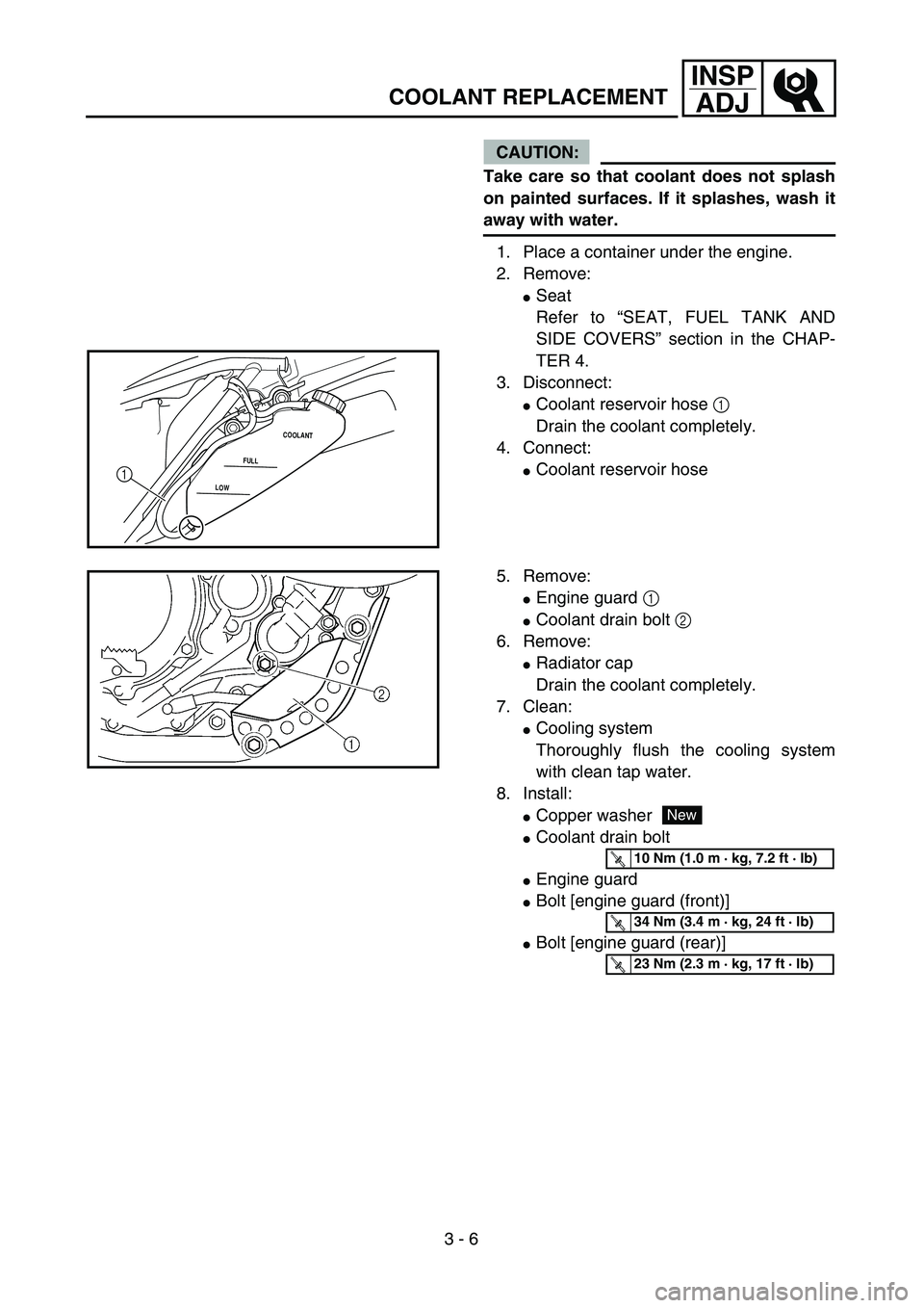
COOLANT REPLACEMENT
CAUTION:
Take care so that coolant does not splash
on painted surfaces. If it splashes, wash it
away with water.
1. Place a container under the engine.
2. Remove:
�Seat
Refer to “SEAT, FUEL TANK AND
SIDE COVERS” section in the CHAP-
TER 4.
3. Disconnect:
�Coolant reservoir hose 1
Drain the coolant completely.
4. Connect:
�Coolant reservoir hoseLOWFULLCOOLANT1
5. Remove:
�Engine guard 1
�Coolant drain bolt 2
6. Remove:
�Radiator cap
Drain the coolant completely.
7. Clean:
�Cooling system
Thoroughly flush the cooling system
with clean tap water.
8. Install:
�Copper washer
�Coolant drain bolt
�Engine guard
�Bolt [engine guard (front)]
�Bolt [engine guard (rear)]
New
T R..10 Nm (1.0 m · kg, 7.2 ft · lb)
T R..34 Nm (3.4 m · kg, 24 ft · lb)
T R..23 Nm (2.3 m · kg, 17 ft · lb)
Page 214 of 754
 3 - 18
INSP
ADJ
PILOT SCREW ADJUSTMENT
10. Install:
�Oil filler plug
11. Inspect:
�Engine (for oil leaks)
�Oil level
Refer to “ENGINE OIL LEVEL INSPEC-
TION”.
12. Check:
�Oil pressure
PILOT SCREW")
3 - 18
INSP
ADJ
PILOT SCREW ADJUSTMENT
10. Install:
�Oil filler plug
11. Inspect:
�Engine (for oil leaks)
�Oil level
Refer to “ENGINE OIL LEVEL INSPEC-
TION”.
12. Check:
�Oil pressure
PILOT SCREW ADJUSTMENT
1. Adjust:
�Pilot screw 1
* Except for USAChecking steps:
�Slightly loosen the oil gallery bolt 1.
�Start the engine and keep it idling until oil
starts to seep from the oil gallery bolt. If no
oil comes out after one minute, turn the
engine off so it will not seize.
�Check oil passages, oil filter and oil pump
for damage or leakage.
�Start the engine after solving the prob-
lem(s) and recheck the oil pressure.
�Tighten the oil gallery bolt to specification.
T R..
Oil gallery bolt:
10 Nm (1.0 m • kg, 7.2 ft • lb)
Adjusting steps:
NOTE:
To optimize the fuel flow at a smaller throttle
opening, each machine’s pilot screw has
been individually set at the factory. Before
adjusting the pilot screw, turn it in fully and
count the number of turns. Record this num-
ber as the factory-set number of turns out.
�Turn in the pilot screw until it is lightly
seated.
�Turn out the pilot screw by the factory-set
number of turns.
Pilot screw:
1-3/4 turns out (example)
*1-1/2 turns out (example)
Page 216 of 754
 3 - 19
INSP
ADJIDLE SPEED ADJUSTMENT/
VALVE CLEARANCE ADJUSTMENT
EC35M021
IDLE SPEED ADJUSTMENT
1. Start the engine and thoroughly warm it
up.
2. Adjust:
�Idle speed
VALVE CLEARANCE ADJUSTMENT
NOTE:
�")
3 - 19
INSP
ADJIDLE SPEED ADJUSTMENT/
VALVE CLEARANCE ADJUSTMENT
EC35M021
IDLE SPEED ADJUSTMENT
1. Start the engine and thoroughly warm it
up.
2. Adjust:
�Idle speed
VALVE CLEARANCE ADJUSTMENT
NOTE:
�The valve clearance should be adjusted
when the engine is cool to the touch.
�The piston must be at Top Dead Center
(T.D.C.) on compression stroke to check or
adjust the valve clearance.
1. Remove:
�Seat
�Fuel tank
Refer to “SEAT, FUEL TANK AND SIDE
COVERS” section in the CHAPTER 4.
2. Remove:
�Carburetor
Refer to “CARBURETOR” section in
the CHAPTER 4.
�Spark plug
�Engine stay (upper)
�Cylinder head cover
Refer to “CAMSHAFTS” section in the
CHAPTER 4. Adjustment steps:
�Adjust the pilot screw.
Refer to “PILOT SCREW ADJUSTMENT”
section.
�Turn the throttle stop screw 1 until the
specified engine idling speed.
NOTE:
Using a digital engine tachometer for idle
speed adjustment, detect the engine idling
speed by bringing the sensing element c of
the engine tachometer close to the ignition
coil 2.
To increase idle speed →
Turn the throttle stop screw 1 in a.
To decrease idle speed →
Turn the throttle stop screw 1 out b.
Engine idling speed:
1,700 ~ 1,900 r/min
c2
Page 272 of 754
 3 - 46
INSP
ADJ
STEERING HEAD INSPECTION AND ADJUSTMENT
�Tighten the ring nut 3 using ring nut
wrench 4.
NOTE:
Set the torque wrench to the ring nut wrench
so that they form a right angle.
Ring nut wr")
3 - 46
INSP
ADJ
STEERING HEAD INSPECTION AND ADJUSTMENT
�Tighten the ring nut 3 using ring nut
wrench 4.
NOTE:
Set the torque wrench to the ring nut wrench
so that they form a right angle.
Ring nut wrench:
YU-33975/90890-01403
T R..
Ring nut (initial tightening):
38 Nm (3.8 m • kg, 27 ft • lb)
�Loosen the ring nut one turn.
�Retighten the ring nut using the ring nut
wrench.
WARNING
Avoid over-tightening.
T R..
Ring nut (final tightening):
7 Nm (0.7 m • kg, 5.1 ft • lb)
�Check the steering shaft by turning it lock
to lock. If there is any binding, remove the
steering shaft assembly and inspect the
steering bearings.
�Install the plain washer 5, handle crown
6, plain washer 7, steering shaft nut 8,
steering shaft cap 9, handlebar 0, han-
dlebar holder A and headlight B.
NOTE:
�The handlebar holder should be installed
with the punched mark a forward.
�Insert the end of the fuel breather hose C
into the hole in the steering shaft cap.
CAUTION:
First tighten the bolts on the front side of
the handlebar holder, and then tighten
the bolts on the rear side.
T R..
Steering shaft nut:
145 Nm (14.5 m • kg, 105 ft • lb)
Handlebar holder:
28 Nm (2.8 m • kg, 20 ft • lb)
Pinch bolt (handle crown):
23 Nm (2.3 m • kg, 17 ft • lb)
Headlight (left and right):
10 Nm (1.0 m • kg, 7.2 ft • lb)
Headlight (lower):
7 Nm (0.7 m • kg, 5.1 ft • lb)
Page 298 of 754
 3 - 57
INSP
ADJ
REPLACING THE HEADLIGHT BULBS
3. Replace:
�Blown fuse
WARNING
Never use a fuse with an amperage rating
other than that specified. Improvising or
using a fuse with the wrong amperage r")
3 - 57
INSP
ADJ
REPLACING THE HEADLIGHT BULBS
3. Replace:
�Blown fuse
WARNING
Never use a fuse with an amperage rating
other than that specified. Improvising or
using a fuse with the wrong amperage rat-
ing may cause extensive damage to the
electrical system, cause the starting and
ignition systems to malfunction and could
possibly cause a fire.
4. Install:
�Fuse cover
�Seat Replacement steps:
�Set the main switch to “OFF”.
�Install a new fuse of the correct amperage.
�Set on the switches to verify if the electri-
cal circuit is operational.
�If the fuse immediately blows again, check
the electrical circuit.
ItemsAmperage
ratingQ’ty
Main fuse 10 A 1
REPLACING THE HEADLIGHT BULBS
1. Remove:
�Headlight
Refer to “SEAT, FUEL TANK AND
SIDE COVERS” section in the CHAP-
TER 4.
2. Remove:
�Headlight bulb holder cover 1
3. Detach:
�Headlight bulb holder 1
4. Remove:
�Headlight bulb 2
WARNING
Since the headlight bulb gets extremely
hot, keep flammable products and your
hands away from the bulb unit it has cooled
down.