Page 354 of 754
 4 - 27
ENGCAMSHAFTS
�Fit the timing chain 3 onto both camshaft
sprockets and install the camshafts on the
cylinder head.
NOTE:
The camshafts should be installed onto the
cylinder head so that the exha")
4 - 27
ENGCAMSHAFTS
�Fit the timing chain 3 onto both camshaft
sprockets and install the camshafts on the
cylinder head.
NOTE:
The camshafts should be installed onto the
cylinder head so that the exhaust cam
sprocket punch mark c and the intake cam
sprocket punch mark d align with the sur-
face of the cylinder head.
CAUTION:
Do not turn the crankshaft during the
camshaft installation. Damage or
improper valve timing will result.
�Install the clips and camshaft caps 4.
T R..
Bolt (camshaft cap):
10 Nm (1.0 m • kg, 7.2 ft • lb)
NOTE:
�Apply the engine oil on the thread and con-
tact surface of the bolts (camshaft cap) 5.
�Tighten the bolts (camshaft cap) in a criss-
cross pattern.
CAUTION:
The bolts (camshaft cap) must be tight-
ened evenly, or damage to the cylinder
head, camshaft caps, and camshaft will
result.
5
4
E
2. Install:
�Timing chain tensioner
Installation steps:
�While pressing the tensioner rod lightly
with fingers, use a thin screwdriver and
wind the tensioner rod up fully clockwise.
Page 356 of 754
4 - 28
ENG
�With the rod fully wound and the chain ten-
sioner UP mark a facing upward, install
the gasket 1 and the chain tensioner 2,
and tighten the bolt 3 to the specified
torque.
T R..
Bolt (timing chain tensioner):
10 Nm (1.0 m • kg, 7.2 ft • lb)
�Release the screwdriver, check the ten-
sioner rod to come out and tighten the
gasket 4 and the cap bolt 5 to the speci-
fied torque.
T R..
Tensioner cap bolt:
7 Nm (0.7 m • kg, 5.1 ft • lb)
5
4New
3. Turn:
�Crankshaft
Counterclockwise several turns
4. Check:
�Rotor “I” mark
Align with the crankcase stationary
pointer.
�Camshaft match marks
Align with the cylinder head surface.
Out of alignment → Adjust.
CAMSHAFTS
Page 442 of 754
4 - 71
ENGKICK AXLE AND SHIFT SHAFT
REMOVAL POINTS
EC4B3101
Kick axle assembly
1. Remove:
�Kick axle assembly 1
NOTE:
Unhook the torsion spring 2 from the hole a
in the crankcase.
EC4C3101
Shift guide and shift lever assembly
1. Remove:
�Bolt (shift guide)
�Shift guide 1
�Shift lever assembly 2
NOTE:
The shift lever assembly is disassembled at
the same time as the shift guide.
EC4N3100
Segment
1. Remove:
�Bolt (segment) 1
�Segment 2
NOTE:
Turn the segment counterclockwise until it
stops and loosen the bolt.
INSPECTION
EC4C4200
Kick axle and ratchet wheel
1. Check:
�Ratchet wheel 1 smooth movement
Unsmooth movement → Replace.
�Kick axle 2
Wear/damage → Replace.
�Spring 3
Broken → Replace.
EC4C4300
Kick gear, kick idle gear and ratchet wheel
1. Inspect:
�Kick gear 1
�Kick idle gear 2
�Ratchet wheel 3
�Gear teeth a
�Ratchet teeth b
Wear/damage → Replace.
Page 450 of 754
4 - 75
ENGKICK AXLE AND SHIFT SHAFT
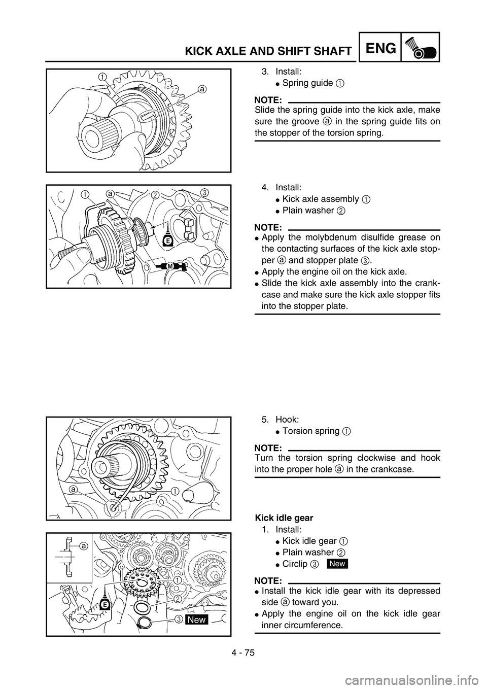
3. Install:
�Spring guide 1
NOTE:
Slide the spring guide into the kick axle, make
sure the groove a in the spring guide fits on
the stopper of the torsion spring.
4. Install:
�Kick axle assembly 1
�Plain washer 2
NOTE:
�Apply the molybdenum disulfide grease on
the contacting surfaces of the kick axle stop-
per a and stopper plate 3.
�Apply the engine oil on the kick axle.
�Slide the kick axle assembly into the crank-
case and make sure the kick axle stopper fits
into the stopper plate.
5. Hook:
�Torsion spring 1
NOTE:
Turn the torsion spring clockwise and hook
into the proper hole a in the crankcase.
Kick idle gear
1. Install:
�Kick idle gear 1
�Plain washer 2
�Circlip 3
NOTE:
�Install the kick idle gear with its depressed
side a toward you.
�Apply the engine oil on the kick idle gear
inner circumference.
New
Page 458 of 754
 4 - 79
ENGAC MAGNETO AND STARTER CLUTCH
Starter clutch
1. Check:
�Starter clutch
Damage/wear → Replace.
2. Check:
�Idle gear
�Idle gear shaft
�Starter clutch gear
Pitting/burrs/chips/roughness/wear")
4 - 79
ENGAC MAGNETO AND STARTER CLUTCH
Starter clutch
1. Check:
�Starter clutch
Damage/wear → Replace.
2. Check:
�Idle gear
�Idle gear shaft
�Starter clutch gear
Pitting/burrs/chips/roughness/wear →
Replace the defective parts.
3. Check:
�Starter clutch operation
�Install the starter clutch drive gear 1 onto
the starter clutch 2 and hold the starter
clutch.
�When turning the starter clutch drive gear
counterclockwise ı, the starter clutch and
the starter clutch drive gear should
engage. If the starter clutch drive gear and
starter clutch do not engage, the starter
clutch is faulty and must be replaced.
�When turning the starter clutch drive gear
clockwise Å, it should turn freely.
If the starter clutch drive gear does not
turn freely, the starter clutch is faulty and
must be replaced.
Torque limiter
1. Check:
�Torque limiter
Damage/wear → Replace.
EC4L5000
ASSEMBLY AND INSTALLATION
AC magneto and starter clutch
1. Install:
�Stator 1
�Bolt (stator) 2
�Pick-up coil 3
�Bolt (pick-up coil) 4
NOTE:
Pass the AC magneto lead 5 under the pick-
up coil.
T R..7 Nm (0.7 m · kg, 5.1 ft · lb)
T R..10 Nm (1.0 m · kg, 7.2 ft · lb)
Page 744 of 754
 7 - 20
TUNSETTING
EC72H002
Suspension setting
�Front fork
NOTE:
�If any of the following symptoms is experienced with the standard position as the base, make
resetting by reference to the adjustment p")
7 - 20
TUNSETTING
EC72H002
Suspension setting
�Front fork
NOTE:
�If any of the following symptoms is experienced with the standard position as the base, make
resetting by reference to the adjustment procedure given in the same chart.
�Before any change, set the rear shock absorber sunken length to the standard figure 90 ~
100 mm (3.5 ~ 3.9 in).
SymptomSection
Check Adjust
JumpLarge
gapMedium
gapSmall
gap
Stiff over entire range
���
Compression damping
Oil level (oil amount)
SpringTurn adjuster counterclockwise (about 2 clicks) to
decrease damping.
Decrease oil level by about 5 ~ 10 mm (0.2 ~ 0.4 in).
Replace with soft spring.
Unsmooth movement
over entire range
����
Outer tube
Inner tube
Under bracket tightening
torqueCheck for any bends, dents, and other noticeable
scars, etc. If any, replace affected parts.
Retighten to specified torque.
Poor initial
movement
�
Rebound damping
Oil sealTurn adjuster counterclockwise (about 2 clicks) to
decrease damping.
Apply grease in oil seal wall.
Soft over entire range,
bottoming out
��
Compression damping
Oil level (oil amount)
SpringTurn adjuster clockwise (about 2 clicks) to increase
damping.
Increase oil level by about 5 ~ 10 mm (0.2 ~ 0.4 in).
Replace with stiff spring.
Stiff toward stroke end
�Oil level (oil amount) Decrease oil level by about 5 mm (0.2 in).
Soft toward stroke end,
bottoming out
�Oil level (oil amount) Increase oil level by about 5 mm (0.2 in).
Stiff initial movement
����Compression dampingTurn adjuster counterclockwise (about 2 clicks) to
decrease damping.
Low front, tending to
lower front posture
��
Compression damping
Rebound damping
Balance with rear end
Oil level (oil amount)Turn adjuster clockwise (about 2 clicks) to increase
damping.
Turn adjuster counterclockwise (about 2 clicks) to
decrease damping.
Set sunken length for 95 ~ 100 mm (3.7 ~ 3.9 in) when
one passenger is astride seat (lower rear posture).
Increase oil level by about 5 mm (0.2 in).
“Obtrusive” front, tend-
ing to upper front pos-
ture
��
Compression damping
Balance with rear end
Spring
Oil lever (oil amount)Turn adjuster counterclockwise (about 2 clicks) to
decrease damping.
Set sunken length for 90 ~ 95 mm (3.5 ~ 3.7 in) when
one passenger is astride seat (upper rear posture).
Replace with soft spring.
Decrease oil level by about 5 ~ 10 mm (0.2 ~ 0.4 in).
Page 745 of 754
 7 - 21
TUNSETTING
�Rear shock absorber
NOTE:
�If any of the following symptoms is experienced with the standard position as the base, make
resetting by reference to the adjustment procedure given in t")
7 - 21
TUNSETTING
�Rear shock absorber
NOTE:
�If any of the following symptoms is experienced with the standard position as the base, make
resetting by reference to the adjustment procedure given in the same chart.
�Adjust the rebound damping in 2-click increments or decrements.
�Adjust the low compression damping in 1-click increments or decrements.
�Adjust the high compression damping in 1/6 turn increments or decrements.
SymptomSection
Check Adjust
JumpLarge
gapMedium
gapSmall
gap
Stiff, tending to sink
��
Rebound damping
Spring set lengthTurn adjuster counterclockwise (about 2 clicks) to
decrease damping.
Set sunken length for 90 ~ 100 mm (3.5 ~ 3.9 in) when
one passenger is astride seat.
Spongy and unstable
��
Rebound damping
Low compression damping
SpringTurn adjuster clockwise (about 2 clicks) to increase
damping.
Turn adjuster clockwise (about 1 click) to increase
damping.
Replace with stiff spring.
Heavy and dragging
��
Rebound damping
SpringTurn adjuster counterclockwise (about 2 clicks) to
decrease damping.
Replace with soft spring.
Poor road gripping
�
Rebound damping
Low compression damping
High compression damp-
ing
Spring set length
SpringTurn adjuster counterclockwise (about 2 clicks) to
decrease damping.
Turn adjuster clockwise (about 1 clicks) to increase
damping.
Turn adjuster clockwise (about 1/6 clicks) to increase
damping.
Set sunken length for 90 ~ 100 mm (3.5 ~ 3.9 in) when
one passenger is astride seat.
Replace with soft spring.
Bottoming out
��
High compression damp-
ing
Spring set length
SpringTurn adjuster clockwise (about 1/6 turn) to increase
damping.
Set sunken length for 90 ~ 100 mm (3.5 ~ 3.9 in) when
one passenger in astride seat.
Replace with stiff spring.
Bouncing
��
Rebound damping
SpringTurn adjuster clockwise (about 2 clicks) to increase
damping.
Replace with soft spring.
Stiff travel
��
High compression damp-
ing
Spring set length
SpringTurn adjuster counterclockwise (about 1/6 turn) to
decrease damping.
Set sunken length for 95 ~ 100 mm (3.7 ~ 3.9 in) when
one passenger is astride seat.
Replace with soft spring.