Page 438 of 754
4 - 69
ENGKICK AXLE AND SHIFT SHAFT
KICK AXLE AND SHIFT SHAFT
KICK AXLE AND SHIFT SHAFT
Extent of removal:1 Kick axle removal2 Kick axle disassembly
3 Shift shaft removal4 Segment removal
Extent of removal Order Part name Q’ty Remarks
KICK AXLE AND SHIFT SHAFT
REMOVAL
Preparation for removal Oil pump Refer to “OIL PUMP” section.
1 Kick idle gear 1
2 Kick axle assembly 1 Refer to “REMOVAL POINTS”.
3 Spring guide 1
4 Torsion spring 1
5 Ratchet wheel 1
6 Kick gear 1
7 Kick axle 1
8 Plain washer 1
9 Shift pedal 1
10 Shift shaft 1
11 Collar 1
12 Torsion spring 1
3
2
1
4
1
Page 446 of 754
4 - 73
ENGKICK AXLE AND SHIFT SHAFT
EC4B5111
Stopper lever
1. Install:
�Torsion spring 1
�Stopper lever 2
�Bolt (stopper lever) 3
NOTE:
Align the stopper lever roller with the slot on
segment.
Shift guide and shift lever assembly
1. Install:
�Spring 1
�Pawl pin 2
�Pawl 3
To shift lever 4.
NOTE:
Apply the engine oil on the springs, pawl pins
and pawls.
2. Install:
�Shift lever assembly 1
To shift guide 2.
T R..10 Nm (1.0 m · kg, 7.2 ft · lb)
1
2
3. Install:
�Shift lever assembly 1
�Shift guide 2
NOTE:
�The shift lever assembly is installed at the
same time as the shift guide.
�Apply the engine oil on the bolt (segment)
shaft.
4. Install:
�Bolt (shift guide) 1
T R..10 Nm (1.0 m · kg, 7.2 ft · lb)
Page 448 of 754
4 - 74
ENGKICK AXLE AND SHIFT SHAFT
EC4C5301
Shift shaft
1. Install:
�Roller 1
�Collar 2
�Torsion spring 3
�Shift shaft 4
NOTE:
Apply the engine oil on the roller and shift
shaft.
2. Install:
�Shift pedal
Refer to “AC MAGNETO AND
STARTER CLUTCH” section.
Kick axle assembly
1. Install:
�Kick gear 1
�Plain washer 2
�Circlip 3
�Ratchet wheel 4
�Spring 5
�Plain washer 6
�Circlip 7
To kick axle 8.
NOTE:
�Apply the molybdenum disulfide oil on the
inner circumferences of the kick gear and
ratchet wheel.
�Align the punch mark a on the ratchet wheel
with the punch mark b on the kick axle.
New
New
2. Install:
�Torsion spring 1
To kick axle 2.
NOTE:
Make sure the stopper a of the torsion spring
fits into the hole b on the kick axle.
Page 450 of 754
4 - 75
ENGKICK AXLE AND SHIFT SHAFT
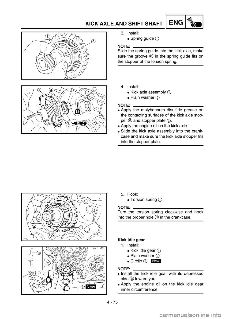
3. Install:
�Spring guide 1
NOTE:
Slide the spring guide into the kick axle, make
sure the groove a in the spring guide fits on
the stopper of the torsion spring.
4. Install:
�Kick axle assembly 1
�Plain washer 2
NOTE:
�Apply the molybdenum disulfide grease on
the contacting surfaces of the kick axle stop-
per a and stopper plate 3.
�Apply the engine oil on the kick axle.
�Slide the kick axle assembly into the crank-
case and make sure the kick axle stopper fits
into the stopper plate.
5. Hook:
�Torsion spring 1
NOTE:
Turn the torsion spring clockwise and hook
into the proper hole a in the crankcase.
Kick idle gear
1. Install:
�Kick idle gear 1
�Plain washer 2
�Circlip 3
NOTE:
�Install the kick idle gear with its depressed
side a toward you.
�Apply the engine oil on the kick idle gear
inner circumference.
New
Page 452 of 754
4 - 76
ENGAC MAGNETO AND STARTER CLUTCH
AC MAGNETO AND STARTER CLUTCH
Extent of removal:1 Starter clutch/wheel gear removal2 Rotor removal
3 Pickup coil/stator removal
Extent of removal Order Part name Q’ty Remarks
AC MAGNETO AND STATOR
REMOVAL
Preparation for removal Drain the engine oil. Refer to “ENGINE OIL REPLACEMENT”
section in the CHAPTER 3.
Seat and fuel tank Refer to “SEAT, FUEL TANK AND SIDE
COVERS” section.
Bolt [radiator (left)]
Disconnect the AC magneto lead.Refer to “RADIATOR” section.
1 Shift pedal 1
2 Engine guard (left) 1
3 Cover (torque limiter) 1
4 Torque limiter 1 Do not disassemble.
5 Crankcase cover (left) 1
6Gasket
1
31
Page 454 of 754
4 - 77
ENGAC MAGNETO AND STARTER CLUTCH
NOTE:
Tighten the rotor nut to 65 Nm (6.5 m·kg, 47 ft·lb), loosen and retighten the rotor nut to 65 Nm
(6.5 m·kg, 47 ft·lb).
Extent of removal Order Part name Q’ty Remarks
7 Dowel pin 2
8 Idle gear 1
9 Bearing 1
10 Shaft 1
11* Nut (rotor) 1 Refer to NOTE.
12 Rotor 1 Use special tool.
Refer to “REMOVAL POINTS”.
13 Woodruff key 1
14 Starter clutch 1
15 Starter clutch drive gear 1
16 Holder 1
17 Pick-up coil 1
18Stator
1
3
2
1
3
Page 458 of 754
 4 - 79
ENGAC MAGNETO AND STARTER CLUTCH
Starter clutch
1. Check:
�Starter clutch
Damage/wear → Replace.
2. Check:
�Idle gear
�Idle gear shaft
�Starter clutch gear
Pitting/burrs/chips/roughness/wear")
4 - 79
ENGAC MAGNETO AND STARTER CLUTCH
Starter clutch
1. Check:
�Starter clutch
Damage/wear → Replace.
2. Check:
�Idle gear
�Idle gear shaft
�Starter clutch gear
Pitting/burrs/chips/roughness/wear →
Replace the defective parts.
3. Check:
�Starter clutch operation
�Install the starter clutch drive gear 1 onto
the starter clutch 2 and hold the starter
clutch.
�When turning the starter clutch drive gear
counterclockwise ı, the starter clutch and
the starter clutch drive gear should
engage. If the starter clutch drive gear and
starter clutch do not engage, the starter
clutch is faulty and must be replaced.
�When turning the starter clutch drive gear
clockwise Å, it should turn freely.
If the starter clutch drive gear does not
turn freely, the starter clutch is faulty and
must be replaced.
Torque limiter
1. Check:
�Torque limiter
Damage/wear → Replace.
EC4L5000
ASSEMBLY AND INSTALLATION
AC magneto and starter clutch
1. Install:
�Stator 1
�Bolt (stator) 2
�Pick-up coil 3
�Bolt (pick-up coil) 4
NOTE:
Pass the AC magneto lead 5 under the pick-
up coil.
T R..7 Nm (0.7 m · kg, 5.1 ft · lb)
T R..10 Nm (1.0 m · kg, 7.2 ft · lb)
Page 460 of 754
4 - 80
ENGAC MAGNETO AND STARTER CLUTCH
2. Install:
�Holder 1
�Bolt 2
NOTE:
�Pass the pick-up coil lead 3 and AC mag-
neto lead 4 under the holder as shown.
�Take care not to catch the AC magneto lead
between crankcase cover ribs.
�Apply the sealant to the grommet of the AC
magneto lead.
Quick gasket:
ACC-QUICK-GS-KT
YAMAHA Bond No. 1215:
90890-85505
T R..7 Nm (0.7 m · kg, 5.1 ft · lb)
3. Install:
�Starter clutch drive gear 1
�Starter clutch 2
NOTE:
Apply the engine oil on the starter clutch drive
gear inner circumference.
4. Install:
�Woodruff key 1
�Rotor 2
NOTE:
�Clean the tapered portions of the crankshaft
and rotor.
�When installing the woodruff key, make sure
that its flat surface a is in parallel with the
crankshaft center line b.
�When installing the rotor, align the keyway c
of the rotor with the woodruff key.
c
2 1 1
ba
 4 - 69
ENGKICK AXLE AND SHIFT SHAFT
KICK AXLE AND SHIFT SHAFT
KICK AXLE AND SHIFT SHAFT
Extent of removal:1 Kick axle removal2 Kick axle disassembly
3 Shift shaft removal4 Segment removal
Extent of re")


 4 - 76
ENGAC MAGNETO AND STARTER CLUTCH
AC MAGNETO AND STARTER CLUTCH
Extent of removal:1 Starter clutch/wheel gear removal2 Rotor removal
3 Pickup coil/stator removal
Extent of removal Order Part nam")
 4 - 77
ENGAC MAGNETO AND STARTER CLUTCH
NOTE:
Tighten the rotor nut to 65 Nm (6.5 m·kg, 47 ft·lb), loosen and retighten the rotor nut to 65 Nm
(6.5 m·kg, 47 ft·lb).
Extent of removal Order Part na")
