Page 16 of 422
 EBU00015
1-CONTENTS
LOCATION OF THE WARNING AND
SPECIFICATION LABELS ...................... 1-1
SAFETY INFORMATION ......................... 2-1
DESCRIPTION AND MACHINE
IDENTIFICATION .............")
EBU00015
1-CONTENTS
LOCATION OF THE WARNING AND
SPECIFICATION LABELS ...................... 1-1
SAFETY INFORMATION ......................... 2-1
DESCRIPTION AND MACHINE
IDENTIFICATION ................................... 3-1
Identification number records ............... 3-3
Key identification number ..................... 3-5
Vehicle identification number ............... 3-7
Model label ........................................... 3-9
CONTROL FUNCTIONS ........................ 4-1
Main switch........................................... 4-1
Indicator and warning lights.................. 4-3
Speedometer ........................................ 4-7
Fuel gauge ........................................... 4-9
Handlebar switches ............................ 4-11
Throttle lever ...................................... 4-17
Speed limiter ...................................... 4-19
Front brake lever ................................ 4-21
Brake pedal and rear brake lever ....... 4-23
Parking brake ..................................... 4-25
Drive select lever ................................ 4-27
1234
Recoil starter ...................................... 4-29
Fuel tank cap ..................................... 4-29
Fuel cock............................................ 4-31
Starter (choke) ................................... 4-33
Seat.................................................... 4-35
Storage box........................................ 4-37
Front carrier ....................................... 4-39
Rear carrier ........................................ 4-39
Front shock absorber adjustment ...... 4-41
Rear shock absorber adjustment ....... 4-43
Auxiliary DC jack ................................ 4-45
PRE-OPERATION CHECKS .................. 5-1
Front and rear brakes .......................... 5-5
Fuel ...................................................... 5-9
Engine oil ........................................... 5-13
Final gear oil ...................................... 5-15
Differential gear oil ............................. 5-17
Coolant............................................... 5-17
Throttle lever ...................................... 5-19
Fittings and fasteners......................... 5-21
Lights ................................................. 5-21
Switches............................................. 5-21
Tires ................................................... 5-23
5
U5TE61.book Page 1 Tuesday, May 6, 2003 4:40 PM
Page 50 of 422
2-15
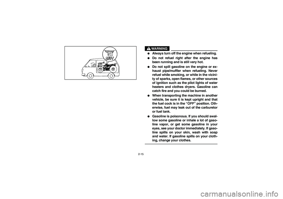
WARNING
_ �
Always turn off the engine when refueling.
�
Do not refuel right after the engine has
been running and is still very hot.
�
Do not spill gasoline on the engine or ex-
haust pipe/muffler when refueling. Never
refuel while smoking, or while in the vicini-
ty of sparks, open flames, or other sources
of ignition such as the pilot lights of water
heaters and clothes dryers. Gasoline can
catch fire and you could be burned.
�
When transporting the machine in another
vehicle, be sure it is kept upright and that
the fuel cock is in the “OFF” position. Oth-
erwise, fuel may leak out of the carburetor
or fuel tank.
�
Gasoline is poisonous. If you should swal-
low some gasoline or inhale a lot of gaso-
line vapor, or get some gasoline in your
eyes, see your doctor immediately. If gaso-
line spills on your skin, wash with soap
and water. If gasoline spills on your cloth-
ing, change your clothes.
_
U5TE61.book Page 15 Tuesday, May 6, 2003 4:40 PM
Page 64 of 422
4-1 1. Main switch
1. Contacteur à clé
1. Interruptor principal
EBU00040
CONTROL FUNCTIONS
EBU12490
Main switch
Functions of the respective switch positions are as
follows:
ON:
The engine can be started only at this position and
the headlights, taillight and meter lighting come on
when the light switch is on.
OFF:
All electrical circuits are switched off. The key can
be removed in this position.
U5TE61.book Page 1 Tuesday, May 6, 2003 4:40 PM
Page 66 of 422
 4-3 1. Coolant temperature warning light “”
2. Reverse indicator light “R”
3. Four-wheel-drive indicator light “”
4. Neutral indicator light “N”
1. Témoin d’avertissement de la temp")
4-3 1. Coolant temperature warning light “”
2. Reverse indicator light “R”
3. Four-wheel-drive indicator light “”
4. Neutral indicator light “N”
1. Témoin d’avertissement de la température du liquide de
refroidissement “”
2. Témoin de marche arrière “R”
3. Témoin 4x4 “”
4. Témoin de point mort “N”
1. Luz de aviso de la temperatura del refrigerante “”
2. Luz de control de marcha atrás “R”
3. Luz de control del modo de tracción de cuatro ruedas “”
4. Luz de control de punto muerto “N”
EBU08020
Indicator and warning lights
EBU01223
Coolant temperature warning light “”
When the coolant temperature reaches a specified
level, this light comes on to warn that the coolant
temperature is too hot. If the light comes on during
operation, stop the engine as soon as it is safe to
do so and allow the engine to cool down for about
10 minutes.
To check the coolant temperature warning light,
shift the drive select lever into neutral, turn the key
to “ON”, and then press the start switch. If the light
does not come on, have a Yamaha dealer inspect
the electrical circuit.CAUTION:_ �
The engine may overheat if the ATV is
overloaded. If this happens, reduce the
load to specification.
�
Restart after making sure that the light is
out. Continuous use while the light is on
may cause damage to the engine.
_
U5TE61.book Page 3 Tuesday, May 6, 2003 4:40 PM
Page 74 of 422
4-11 1. Light switch “//OFF”
2. Engine stop switch “/”
3. Start switch “”
4. Horn switch “”
1. Contacteur d’éclairage “//OFF”
2. Coupe-circuit du moteur “/”
3. Contacteur du démarreur “”
4. Contacteur de l’avertisseur “”
1. Interruptor de luces “//OFF”
2. Interruptor de paro del motor “/”
3. Interruptor de arranque “”
4. Interruptor de la bocina “”
EBU00053
Handlebar switches
EBU12510
Light switch “/ /OFF”
Set the switch to “” to turn on the low beams,
the taillight and the meter lighting.
Set the switch to “” to turn on the high beams,
the taillight and the meter lighting.
Set the switch to “OFF” to turn off all the lights.CAUTION:_ Do not use the headlights with the engine
turned off for more than thirty minutes. The
battery may discharge to the point that the
starter motor will not operate properly. If this
should happen, remove the battery and re-
charge it. _
U5TE61.book Page 11 Tuesday, May 6, 2003 4:40 PM
Page 108 of 422
4-45 1. Auxiliary DC jack cap
1. Capuchon de la prise pour accessoires
1. Tapa de la toma de CC auxiliar
1. Auxiliary DC jack
1. Prise pour accessoires
1. Toma de CC auxiliar
EBU10020
Auxiliary DC jack
The auxiliary DC jack is located at the front right
side of the ATV. The auxiliary DC jack can be used
for suitable work lights, radios, etc. The auxiliary
DC jack should only be used when the engine is
running.
1. Set the light switch to “OFF”.
2. Start the engine. (See pages 6-3–6-7.)
3. Open the auxiliary DC jack cap, and then in-
sert the accessory power plug into the jack.
4. When the auxiliary DC jack is not being used,
cover it with the cap. Maximum rated capacity for the auxiliary DC
jack:
DC 12 V, 120 W (10 A)
U5TE61.book Page 45 Tuesday, May 6, 2003 4:40 PM
Page 110 of 422
4-47
CAUTION:_ �
Do not use accessories requiring more
than the above maximum capacity. This
may overload the circuit and cause the
fuse to blow.
�
If accessories are used without the engine
running or with the headlights turned on,
the battery will lose its charge and engine
starting may become difficult.
�
Do not use an automotive cigarette lighter
or other accessories with a plug that gets
hot because the jack can be damaged.
_
U5TE61.book Page 47 Tuesday, May 6, 2003 4:40 PM
Page 112 of 422
 5-1
EBU00113
PRE-OPERATION CHECKS
Before using this machine, check the following points:
ITEM ROUTINE PAGE
Front brakeCheck operation, free play, fluid level and fluid leakage.
Fill with DOT 4 brake")
5-1
EBU00113
PRE-OPERATION CHECKS
Before using this machine, check the following points:
ITEM ROUTINE PAGE
Front brakeCheck operation, free play, fluid level and fluid leakage.
Fill with DOT 4 brake fluid if necessary.5-5–5-7,
8-87–8-95
Rear brakeCheck operation, condition and free play.
Adjust if necessary.5-5–5-7,
8-87, 8-97–8-101
FuelCheck fuel level.
Fill with fuel if necessary.5-9–5-11
Engine oilCheck oil level.
Fill with oil if necessary.5-13, 8-29–8-39
Coolant reservoirCheck coolant level in reservoir.
Fill with coolant if necessary.8-51–8-61
Final gear oil and
differential gear oilCheck for leakage.5-15–5-17,
8-39–8-49
ThrottleCheck for proper throttle cable operation. 5-19, 8-85
Wheels and tiresCheck tire pressure, wear and damage.5-23–5-29,
8-109–8-111
Fittings and fastenersCheck all fittings and fasteners. 5-21
Lights and switchesCheck for proper operation. 5-21, 8-123–8-127
Axle bootsCheck for damage. 8-61
U5TE61.book Page 1 Tuesday, May 6, 2003 4:40 PM
 4-1 1. Main switch
1. Contacteur à clé
1. Interruptor principal
EBU00040
CONTROL FUNCTIONS
EBU12490
Main switch
Functions of the respective switch positions are as
follows:
ON:
The engine can be s")
 4-11 1. Light switch “//OFF”
2. Engine stop switch “/”
3. Start switch “”
4. Horn switch “”
1. Contacteur d’éclairage “//OFF”
2. Coupe-circuit du moteur “/”
3. Contacteur du")
 4-45 1. Auxiliary DC jack cap
1. Capuchon de la prise pour accessoires
1. Tapa de la toma de CC auxiliar
1. Auxiliary DC jack
1. Prise pour accessoires
1. Toma de CC auxiliar
EBU10020
Auxiliary DC ja")
