Page 16 of 422
 EBU00015
1-CONTENTS
LOCATION OF THE WARNING AND
SPECIFICATION LABELS ...................... 1-1
SAFETY INFORMATION ......................... 2-1
DESCRIPTION AND MACHINE
IDENTIFICATION .............")
EBU00015
1-CONTENTS
LOCATION OF THE WARNING AND
SPECIFICATION LABELS ...................... 1-1
SAFETY INFORMATION ......................... 2-1
DESCRIPTION AND MACHINE
IDENTIFICATION ................................... 3-1
Identification number records ............... 3-3
Key identification number ..................... 3-5
Vehicle identification number ............... 3-7
Model label ........................................... 3-9
CONTROL FUNCTIONS ........................ 4-1
Main switch........................................... 4-1
Indicator and warning lights.................. 4-3
Speedometer ........................................ 4-7
Fuel gauge ........................................... 4-9
Handlebar switches ............................ 4-11
Throttle lever ...................................... 4-17
Speed limiter ...................................... 4-19
Front brake lever ................................ 4-21
Brake pedal and rear brake lever ....... 4-23
Parking brake ..................................... 4-25
Drive select lever ................................ 4-27
1234
Recoil starter ...................................... 4-29
Fuel tank cap ..................................... 4-29
Fuel cock............................................ 4-31
Starter (choke) ................................... 4-33
Seat.................................................... 4-35
Storage box........................................ 4-37
Front carrier ....................................... 4-39
Rear carrier ........................................ 4-39
Front shock absorber adjustment ...... 4-41
Rear shock absorber adjustment ....... 4-43
Auxiliary DC jack ................................ 4-45
PRE-OPERATION CHECKS .................. 5-1
Front and rear brakes .......................... 5-5
Fuel ...................................................... 5-9
Engine oil ........................................... 5-13
Final gear oil ...................................... 5-15
Differential gear oil ............................. 5-17
Coolant............................................... 5-17
Throttle lever ...................................... 5-19
Fittings and fasteners......................... 5-21
Lights ................................................. 5-21
Switches............................................. 5-21
Tires ................................................... 5-23
5
U5TE61.book Page 1 Tuesday, May 6, 2003 4:40 PM
Page 50 of 422
2-15
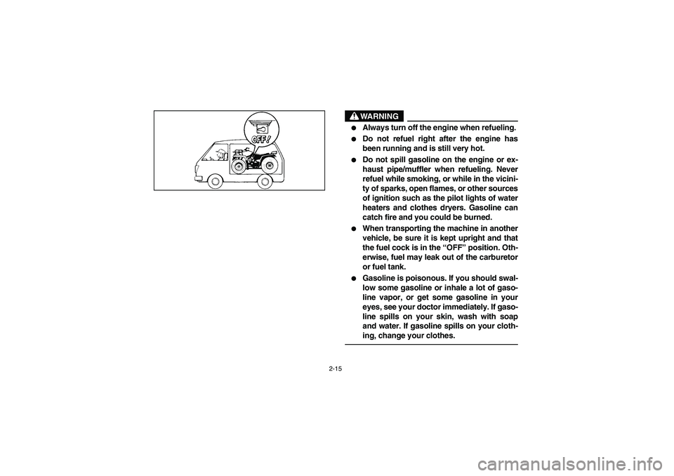
WARNING
_ �
Always turn off the engine when refueling.
�
Do not refuel right after the engine has
been running and is still very hot.
�
Do not spill gasoline on the engine or ex-
haust pipe/muffler when refueling. Never
refuel while smoking, or while in the vicini-
ty of sparks, open flames, or other sources
of ignition such as the pilot lights of water
heaters and clothes dryers. Gasoline can
catch fire and you could be burned.
�
When transporting the machine in another
vehicle, be sure it is kept upright and that
the fuel cock is in the “OFF” position. Oth-
erwise, fuel may leak out of the carburetor
or fuel tank.
�
Gasoline is poisonous. If you should swal-
low some gasoline or inhale a lot of gaso-
line vapor, or get some gasoline in your
eyes, see your doctor immediately. If gaso-
line spills on your skin, wash with soap
and water. If gasoline spills on your cloth-
ing, change your clothes.
_
U5TE61.book Page 15 Tuesday, May 6, 2003 4:40 PM
Page 54 of 422
3-1
EBU00032
DESCRIPTION AND MACHINE
IDENTIFICATION1. Rear shock absorber
assembly spring preload
adjusting ring
2. Storage box and tool kit
3. Spark plug
4. Front shock absorber
assembly spring preload
adjusting ring
5. Brake pedal
6. V-belt case
7. Radiator cap
8. Fuel cock
9. Air filter case
10. Fuses
11. Tail/brake light
12. Front shock absorber
assembly spring preload
adjusting ring
13. V-belt cooling duct check
hose14. Coolant reservoir
15. Oil filter cartridge
16. Engine oil dipstick
17. Rear brake lever
18. Left handlebar switches
19. Starter (choke)
20. Horn switch
21. Drive select lever
22. Speedometer
23. Main switch
24. Fuel tank cap
25. Auxiliary DC jack
26. Right handlebar
switch
27. Throttle lever
28. Front brake leverNOTE:The machine you have purchased may differ
slightly from those shown in the figures of this
manual.
U5TE61.book Page 1 Tuesday, May 6, 2003 4:40 PM
Page 70 of 422
4-7 1. Speedometer 2. Trip odometer
3. Reset knob
1. Compteur de vitesse 2. Totalisateur journalier
3. Bouton de remise à zéro
1. Velocímetro 2. Cuentakilómetros parcial
3. Perilla de reposición
EBU00447
Speedometer
The speedometer shows riding speed. This
speedometer is equipped with a trip odometer.
The trip odometer can be reset to “0” with the reset
knob. Use the trip odometer to estimate how far
you can ride on a tank of fuel before going to re-
serve. This information will enable you to plan fuel
stops in the future.
U5TE61.book Page 7 Tuesday, May 6, 2003 4:40 PM
Page 72 of 422
4-9 1. Fuel gauge
2. Red line
1. Jauge de carburant
2. Ligne rouge
1. Indicador del nivel de combustible
2. Línea roja
EBU00052
Fuel gauge
The fuel gauge indicates the amount of fuel in the
fuel tank. When the needle reaches the red line,
refill the tank at the first opportunity.NOTE:If the machine runs out of fuel, move the fuel cock
lever to the “RES” position. Approximately 4.5 L of
fuel will be remaining in the tank.
U5TE61.book Page 9 Tuesday, May 6, 2003 4:40 PM
Page 92 of 422
4-29 1. Recoil starter
1. Lanceur à réenroulement
1. Arranque por tracción de cable
1. Fuel tank cap
1. Bouchon du réservoir de carburant
1. Tapón del depósito de combustible
EBU01264
Recoil starter
Firmly grasp the handle and pull slightly until en-
gagement can be felt. Then pull forcefully, being
careful not to pull the rope all the way out.
WARNING
_ Shift the drive select lever into the neutral po-
sition and apply the parking brake before start-
ing the engine or the ATV could start to move
unexpectedly, which could cause an accident. _
EBU00092
Fuel tank cap
Remove the fuel tank cap by turning it counter-
clockwise.
U5TE61.book Page 29 Tuesday, May 6, 2003 4:40 PM
Page 94 of 422
4-31 1. Arrow mark pointing to “OFF”
1. Flèche dirigée vers “OFF”
1. Marca de la flecha señalando a “OFF”
OFF position
Robinet fermé
Posición OFF1. Arrow mark pointing to “ON”
1. Flèche dirigée vers “ON”
1. Marca de la flecha señalando a “ON”ON position
Robinet ouvert
Posición ON
EBU00093
Fuel cock
The fuel cock supplies fuel from the fuel tank to the
carburetor.
The fuel cock has three positions.
OFF: With the lever in this position, fuel will not
flow. Always turn the lever to this position
when the engine is not running.
ON: With the lever in this position, fuel flows to
the carburetor. Normal riding is done with
the lever in this position.
U5TE61.book Page 31 Tuesday, May 6, 2003 4:40 PM
Page 96 of 422
4-33 1. Arrow mark pointing to “RES”
1. Flèche dirigée vers “RES”
1. Marca de la flecha señalando a “RES”
RES position
Réserve
Posición RES1. Starter (choke) “”
1. Starter (enrichisseur) “”
1. Starter (choke) “”
RES: This indicates reserve. If you run out of fuel
while riding, turn the lever to this position.
THEN FILL THE FUEL TANK AT THE
FIRST OPPORTUNITY. After refuelling, re-
turn the fuel cock lever to the “ON” position.
EBU00095
Starter (choke) “”
Starting a cold engine requires a richer air-fuel
mixture. A separate starter circuit supplies this
mixture.
Move in direction
a to turn on the starter (choke).
Move in direction
b to turn off the starter (choke).
Refer to “Starting a cold engine” for proper opera-
tion. (See pages 6-3–6-7.)
U5TE61.book Page 33 Tuesday, May 6, 2003 4:40 PM
 3-1
EBU00032
DESCRIPTION AND MACHINE
IDENTIFICATION1. Rear shock absorber
assembly spring preload
adjusting ring
2. Storage box and tool kit
3. Spark plug
4. Front shock absorber
assembly spring p")
 4-7 1. Speedometer 2. Trip odometer
3. Reset knob
1. Compteur de vitesse 2. Totalisateur journalier
3. Bouton de remise à zéro
1. Velocímetro 2. Cuentakilómetros parcial
3. Perilla de reposición")
 4-9 1. Fuel gauge
2. Red line
1. Jauge de carburant
2. Ligne rouge
1. Indicador del nivel de combustible
2. Línea roja
EBU00052
Fuel gauge
The fuel gauge indicates the amount of fuel in the
fuel tan")
 4-29 1. Recoil starter
1. Lanceur à réenroulement
1. Arranque por tracción de cable
1. Fuel tank cap
1. Bouchon du réservoir de carburant
1. Tapón del depósito de combustible
EBU01264
Recoil sta")
 4-31 1. Arrow mark pointing to “OFF”
1. Flèche dirigée vers “OFF”
1. Marca de la flecha señalando a “OFF”
OFF position
Robinet fermé
Posición OFF1. Arrow mark pointing to “ON”
1.")
 4-33 1. Arrow mark pointing to “RES”
1. Flèche dirigée vers “RES”
1. Marca de la flecha señalando a “RES”
RES position
Réserve
Posición RES1. Starter (choke) “”
1. Starter (enrich")