Page 136 of 364
3 - 5
INSP
ADJ
ENGINE OIL LEVEL INSPECTION
1. Start the engine, warm it up for several
minutes and wait for five minutes.
2. Place the machine on a level place and
hold it up on upright position by placing
the suitable stand under the engine.
3. Remove:
�
Dipstick
1
4. Check:
�
Oil level
Oil level should be between maximum
a
and minimum
b
marks.
Oil level is low
→
Add oil to proper
level.
NOTE:
When inspecting the oil level, do not screw the
dipstick into the oil tank. Insert the gauge
lightly.
(For USA and CDN)
CAUTION:
�
Do not add any chemical additives.
Engine oil also lubricates the clutch and
additives could cause clutch slippage.
�
Do not allow foreign material to enter the
crankcase.
Recommended oil:
At –10 ˚C (10 ˚F) or higher
Å
:
Yamalube 4 (10W-30) or SAE
10W-30 type SE/SF motor oil
At 5 ˚C (40 ˚F) or higher
ı
:
Yamalube 4 (20W-40) or SAE
20W-40 type SE/SF motor oil
010 30 50 70
90110
130
-20
-10010
20 30 40
50
Å
ı
˚C ˚F
ENGINE OIL LEVEL INSPECTION
Page 142 of 364

3 - 8
INSP
ADJIDLE SPEED ADJUSTMENT/
VALVE CLEARANCE ADJUSTMENT
IDLE SPEED ADJUSTMENT
1. Start the engine and thoroughly warm it
up.
2. Attach:
�Inductive tachometer
To spark plug lead.
3. Adjust:
�Idle speed
VALVE CLEARANCE ADJUSTMENT
NOTE:
�The valve clearance should be adjusted
when the engine is cool to the touch.
�The piston must be at Top Dead Center
(T.D.C.) on compression stroke to check or
adjust the valve clearance.
1. Remove:
�Air scoop (right) 1
�Air filter case 2
2. Remove:
�Spark plug
�Tappet cover (intake side) 1
�Tappet cover (exhaust side) 2 Adjustment steps:
�Adjust the pilot screw.
Refer to “PILOT AIR SCREW ADJUST-
MENT” section.
�Turn the throttle stop screw 1 until the
engine runs at the lowest possible speed.
To increase idle speed →
Turn the throttle stop screw 1 in a.
To decrease idle speed →
Turn the throttle stop screw 1 out b.
Inductive tachometer:
YU-8036-B/90890-03113
Engine idling speed:
1,400 ~ 1,600 r/min
3. Remove:
�Timing plug 1
�Crankshaft end cover 2
�O-rings
Page 150 of 364

3 - 12
INSP
ADJ
DRIVE CHAIN SLACK ADJUSTMENT
DRIVE CHAIN SLACK ADJUSTMENT
1. Elevate the rear wheel by placing the
suitable stand under the engine.
2. Check:
�Drive chain slack a
In the center between the drive axle
and rear wheel axle.
Out of specification → Adjust.
NOTE:
Before checking and/or adjusting, rotate the
rear wheel through several revolutions and
check the slack several times to find the tight-
est point. Check and/or adjust chain slack with
rear wheel in this “tight chain” position.
Drive chain slack:
40 ~ 53 mm (1.6 ~ 2.1 in)
3. Adjust:
�Drive chain slack
Drive chain slack adjustment steps:
�Loosen the wheel axle nut 1 and locknuts
2.
�Adjust chain slack by turning the adjusters
3.
To tighten →Turn adjuster 3 clockwise.
To loosen →Turn adjuster 3 counter-
clockwise and push wheel
forward.
�Turn each adjuster exactly the same
amount to maintain correct axle alignment.
(There are marks a on each side of chain
puller alignment.)
NOTE:
Turn the adjuster so that the chain is in line
with the sprocket, as viewed from the rear.
CAUTION:
Too small chain slack will overload the
engine and other vital parts; keep the
slack within the specified limits.
13 a2
Page 156 of 364
3 - 15
INSP
ADJSPOKES INSPECTION AND TIGHTENING/WHEEL INSPECTION/
STEERING HEAD INSPECTION AND ADJUSTMENT
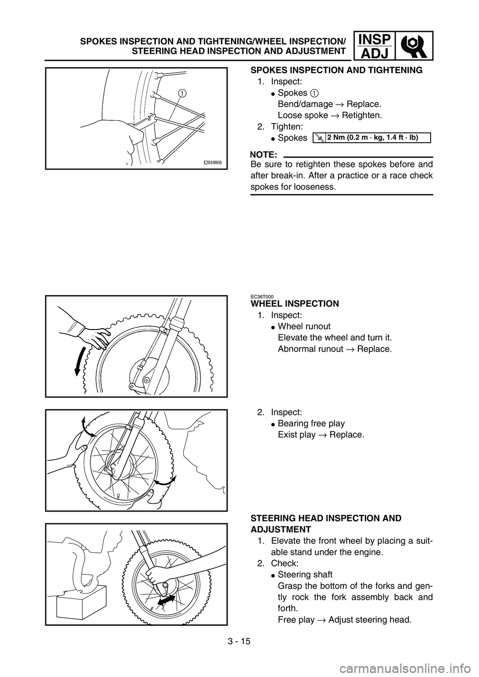
SPOKES INSPECTION AND TIGHTENING
1. Inspect:
�Spokes 1
Bend/damage → Replace.
Loose spoke → Retighten.
2. Tighten:
�Spokes
NOTE:
Be sure to retighten these spokes before and
after break-in. After a practice or a race check
spokes for looseness.
T R..2 Nm (0.2 m · kg, 1.4 ft · lb)
EC36T000
WHEEL INSPECTION
1. Inspect:
�Wheel runout
Elevate the wheel and turn it.
Abnormal runout → Replace.
2. Inspect:
�Bearing free play
Exist play → Replace.
STEERING HEAD INSPECTION AND
ADJUSTMENT
1. Elevate the front wheel by placing a suit-
able stand under the engine.
2. Check:
�Steering shaft
Grasp the bottom of the forks and gen-
tly rock the fork assembly back and
forth.
Free play → Adjust steering head.
Page 166 of 364
3 - 20
INSP
ADJ
ELECTRICAL/SPARK PLUG INSPECTION
EC370000
ELECTRICAL
EC371001
SPARK PLUG INSPECTION
1. Remove:
�Spark plug
2. Inspect:
�Electrode 1
Wear/damage → Replace.
�Insulator color 2
Normal condition is a medium to light
tan color.
Distinctly different color → Check the
engine condition.
NOTE:
When the engine runs for many hours at low
speeds, the spark plug insulator will become
sooty, even if the engine and carburetor are in
good operating condition.
3. Measure:
�Plug gap a
Use a wire gauge or thickness gauge.
Out of specification → Regap.
4. Clean the plug with a spark plug cleaner
if necessary.
Spark plug gap:
0.6 ~ 0.7 mm (0.02 ~ 0.03 in)
Standard spark plug:
CR6HSA (NGK)
U20FSR-U (DENSO)
5. Tighten:
�Spark plug
NOTE:
�Before installing a spark plug, clean the gas-
ket surface and plug surface.
�Finger-tighten a the spark plug before
torquing to specification b.
T R..13 Nm (1.3 m · kg, 9.4 ft · lb)
Page 284 of 364
4 - 50
ENGSHIFT FORK, SHIFT CAM AND TRANSMISSION
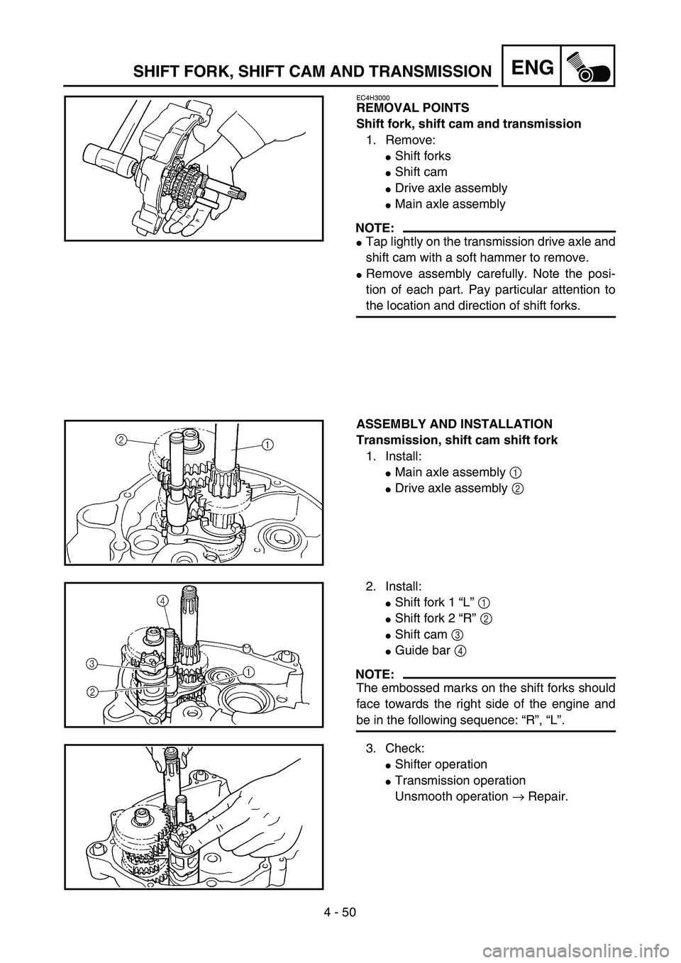
EC4H3000
REMOVAL POINTS
Shift fork, shift cam and transmission
1. Remove:
�Shift forks
�Shift cam
�Drive axle assembly
�Main axle assembly
NOTE:
�Tap lightly on the transmission drive axle and
shift cam with a soft hammer to remove.
�Remove assembly carefully. Note the posi-
tion of each part. Pay particular attention to
the location and direction of shift forks.
ASSEMBLY AND INSTALLATION
Transmission, shift cam shift fork
1. Install:
�Main axle assembly 1
�Drive axle assembly 2
2. Install:
�Shift fork 1 “L” 1
�Shift fork 2 “R” 2
�Shift cam 3
�Guide bar 4
NOTE:
The embossed marks on the shift forks should
face towards the right side of the engine and
be in the following sequence: “R”, “L”.
3. Check:
�Shifter operation
�Transmission operation
Unsmooth operation → Repair.
Page 316 of 364
–+ELEC
6 - 3
IGNITION SYSTEM
EC620000
IGNITION SYSTEM
INSPECTION STEPS
Use the following steps for checking the possibility of the malfunctioning engine being attributable to
ignition system failure and for checking the spark plug which will not spark.
NOTE:
�
Remove the following parts before inspection.
1) Seat
2) Fuel tank
�
Use the following special tools in this inspection.
Spark gap testClean or replace
spark plug.
Check entire ignition
system for connection.Repair or replace.
Check main switch.
(TT-R90E only)Replace.
Check “ENGINE STOP”
switch.Replace.
Check ignition coil. Primary coil Replace.
Secondary coil Replace.
Check CDI magneto. Pickup coil Replace.
Source coil Replace.
Replace CDI unit.
Dynamic spark tester:
YM-34487
Ignition checker:
90890-06754
Pocket tester:
YU-3112-C/90890-03112
No Spark
OK
OK
OK
OK
Spark
No good
No good
No good
No good
No good
No good
OK
No good
Page 320 of 364
6 - 4
–+ELEC
IGNITION SYSTEM
EC622001
SPARK GAP TEST
1. Disconnect the spark plug cap from spark
plug.
2. Connect the dynamic spark tester
1
(ignition checker
2
) as shown.
�
Spark plug cap
3
�
Spark plug
4
Å
For USA and CDN
ı
Except for USA and CDN
3. Kick the kick starter.
4. Check the ignition spark gap.
5. Start engine, and increase spark gap until
misfire occurs. (for USA and CDN only)
Minimum spark gap:
6.0 mm (0.24 in)
Å
ı
EC624000
COUPLERS AND LEADS CONNECTION
INSPECTION
1. Check:
�Couplers and leads connection
Rust/dust/looseness/short-circuit →
Repair or replace.
MAIN SWITCH INSPECTION (TT-R90E)
1. Inspect:
�Main switch continuity
Check for continuity as follows:
Incorrect continuity → Replace. Tester (+) → Red lead 1
Tester (–) → Brown lead 2 Continuous
Tester (+) →
Black/White lead 3
Tester (–) → Black lead 4 Continuous
R
1Br
2B/W
3B
4Tester selec-
tor position
ON
Ω × 1
OFF
B/W
BrR
B
1
3
2
4