Page 264 of 364
4 - 40
ENG
REMOVAL POINTS
Rotor
1. Remove:
�Rotor nut 1
�Washer 2
NOTE:
�Loosen the rotor nut while holding the rotor
with sheave holder 3.
�Do not allow the sheave holder to touch the
projection on the rotor.
Sheave holder:
YS-1880-A/90890-01701
2. Remove:
�Rotor 1
�Woodruff key
NOTE:
�Use the flywheel puller 2.
�Center the flywheel puller over the rotor.
Make sure after installing the holding bolts
that the clearance between the flywheel
puller and the rotor is the same everywhere.
If necessary, one holding bolt may be turned
out slightly to adjust the flywheel puller’s
position.
CAUTION:
Cover the crankshaft end with the box
wrench for protection.
Flywheel puller:
YU-33270-B/90890-01362
CDI MAGNETO (TT-R90)
Page 268 of 364
4 - 42
ENGCDI MAGNETO AND STARTER CLUTCH (TT-R90E)
REMOVAL POINTS
Rotor
1. Remove:
�Rotor nut 1
�Washer 2
NOTE:
�Loosen the rotor nut while holding the rotor
with sheave holder 3.
�Do not allow the sheave holder to touch the
projection on the rotor.
Sheave holder:
YS-1880-A/90890-01701
2. Remove:
�Rotor 1
�Woodruff key
NOTE:
�Use the flywheel puller 2.
�Center the flywheel puller over the rotor.
Make sure after installing the holding bolts
that the clearance between the flywheel
puller and the rotor is the same everywhere.
If necessary, one holding bolt may be turned
out slightly to adjust the flywheel puller’s
position.
CAUTION:
Cover the crankshaft end with the box
wrench for protection.
Flywheel puller:
YU-33270-B/90890-01362
Page 284 of 364
4 - 50
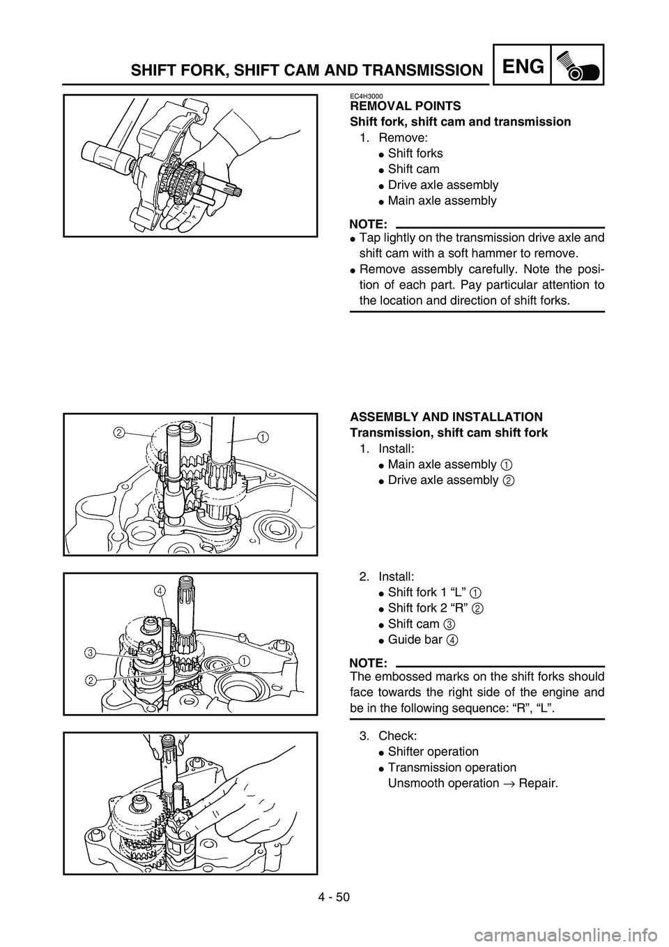
ENGSHIFT FORK, SHIFT CAM AND TRANSMISSION
EC4H3000
REMOVAL POINTS
Shift fork, shift cam and transmission
1. Remove:
�Shift forks
�Shift cam
�Drive axle assembly
�Main axle assembly
NOTE:
�Tap lightly on the transmission drive axle and
shift cam with a soft hammer to remove.
�Remove assembly carefully. Note the posi-
tion of each part. Pay particular attention to
the location and direction of shift forks.
ASSEMBLY AND INSTALLATION
Transmission, shift cam shift fork
1. Install:
�Main axle assembly 1
�Drive axle assembly 2
2. Install:
�Shift fork 1 “L” 1
�Shift fork 2 “R” 2
�Shift cam 3
�Guide bar 4
NOTE:
The embossed marks on the shift forks should
face towards the right side of the engine and
be in the following sequence: “R”, “L”.
3. Check:
�Shifter operation
�Transmission operation
Unsmooth operation → Repair.
Page 342 of 364
6 - 14
–+ELEC
5. Measure:
�Brush length a
Out of specification → Replace.
Brush length wear limit:
3.5 mm (0.14 in)
6. Measure:
�Brush spring force
Fatigue/out of specification → Replace
as a set.
Brush spring force:
3.92 ~ 5.88 N
(400 ~ 600 g, 14.1 ~ 21.2 oz)
ASSEMBLY
1. Install:
�Brush holder
2. Install:
�Armature coil 1
3. Install:
�Ring 1
�Stator assembly 2
�Front bracket 3
NOTE:
�Apply molybdenum grease lightly on to the
bearings of the starter motor.
�Align the match mark on the yoke with the
match mark on the bracket.
ELECTRIC STARTING SYSTEM (TT-R90E)
Page 344 of 364
–+ELEC
6 - 15
CHARGING SYSTEM (TT-R90E)
EC680000
CHARGING SYSTEM (TT-R90E)
EC681001
INSPECTION STEPS
If the battery is not charged, use the following inspection steps.
*1 marked: Refer to “FUSE INSPECTION” section in the CHAPTER 3.
*2 marked: Refer to “CHECKING AND CHARGING THE BATTERY” section in the CHAPTER 3.
NOTE:
�Remove the following parts before inspection.
1) Seat
2) Rear fender
3) Fuel tank
�Use the following special tool in this inspection.
Pocket tester:
YU-3112-C/90890-03112Inductive tachometer:
YU-8036-B
Engine tachometer:
90890-03113
*1 Check fuse.Replace fuse and
check wire harness.
*2 Check battery. Recharge or replace.
Check each coupler and
wire connection.Repair or replace.
Check charging voltage.Charging system is
good.
Check CDI magneto. Lighting coil Replace.
Replace rectifier/regulator.
OK
OK
OK
No good
OK
No good
No good
No good
No good
OK
Page 348 of 364
6 - 16
–+ELECCHARGING SYSTEM (TT-R90E)
EC624000
COUPLERS AND LEADS CONNECTION
INSPECTION
1. Check:
�Couplers and leads connection
Rust/dust/looseness/short-circuit →
Repair or replace.
CHARGING VOLTAGE INSPECTION
1. Start the engine.
2. Inspect:
�Charging voltage
Out of specification → If no failure is
found in checking the source coil resis-
tance, replace the rectifier/regulator.
Tester (+) lead → Red lead 1
Tester (–) lead → Black lead 2
Charging
voltageTester selector
position
14.0 ~ 15.0 V at
5,000 r/minDCV-20
WB
R
Y/R
12
3. Inspect:
�Lighting coil resistance
Out of specification → Replace.
Tester (+) lead → White lead 1
Tester (–) lead → Black lead 2
Lighting coil
resistanceTester selector
position
0.64 ~ 0.96 Ω at
20 ˚C (68 ˚F)Ω × 1
WSb
YB
1
2
Page 350 of 364
–+ELEC
6 - 17
CARBURETOR HEATING SYSTEM
CARBURETOR HEATING SYSTEM
INSPECTION STEPS
Use the following steps for checking the possibility of the malfunctioning carburetor heating system.
NOTE:
�Remove the following parts before inspection.
1) Seat
2) Fuel tank
�Use the following special tools in this inspection.
Check entire carburetor
heating system for connec-
tion.Repair or replace.
Check thermo switch. Replace.
Check carburetor heater. Replace.
Check CDI magneto. Lighting coil Replace.
Replace rectifier/regulator.
Pocket tester:
YU-3112-C/90890-03112
OK
OK
OK
No good
No good
No good
No good
OK
Page 358 of 364
6 - 20
–+ELECCARBURETOR HEATING SYSTEM
CARBURETOR HEATER INSPECTION
1. Inspect:
�Carburetor heater resistance
Out of specification → Replace.
Tester (+) probe →
Carburetor heater terminal 1
Tester (–) probe →
Carburetor heater body 2
Carburetor
heater resistanceTester selector
position
6 ~ 10 Ω at
20 ˚C (68 ˚F)Ω × 1
CDI MAGNETO INSPECTION
1. Inspect:
�Lighting coil resistance
Out of specification → Replace.
ÅTT-R90
ıTT-R90E
Tester (+) lead → Yellow lead 1
Tester (–) lead → Black lead 2
Lighting coil
resistanceTester selector
position
TT-R90:
0.28 ~ 0.42 Ω at
20 ˚C (68 ˚F)
TT-R90E:
0.52 ~ 0.78 Ω at
20 ˚C (68 ˚F)Ω × 1
W
Y
B
WSb
YB
1
2
1
2
Å
ı
Page:
< prev 1-8 9-16 17-24


 –+ELEC
6 - 15
CHARGING SYSTEM (TT-R90E)
EC680000
CHARGING SYSTEM (TT-R90E)
EC681001
INSPECTION STEPS
If the battery is not charged, use the following inspection steps.
*1 marked: Refer to “FUSE IN")


