Page 214 of 610
3 - 21
INSP
ADJ
DRIVE CHAIN INSPECTION
EC369002
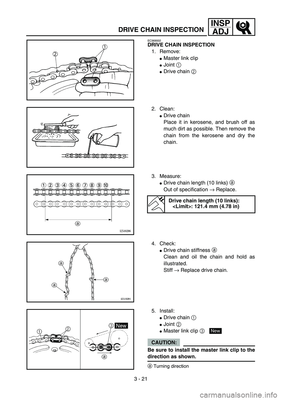
DRIVE CHAIN INSPECTION
1. Remove:
�Master link clip
�Joint 1
�Drive chain 2
2. Clean:
�Drive chain
Place it in kerosene, and brush off as
much dirt as possible. Then remove the
chain from the kerosene and dry the
chain.
3. Measure:
�Drive chain length (10 links) a
Out of specification → Replace.
Drive chain length (10 links):
: 121.4 mm (4.78 in)
4. Check:
�Drive chain stiffness a
Clean and oil the chain and hold as
illustrated.
Stiff → Replace drive chain.
5. Install:
�Drive chain 1
�Joint 2
�Master link clip 3
CAUTION:
Be sure to install the master link clip to the
direction as shown.
aTurning direction
New
Page 216 of 610

3 - 22
INSP
ADJ
DRIVE CHAIN SLACK ADJUSTMENT
6. Lubricate:
�Drive chain
Drive chain lubricant:
SAE 10W-30 motor oil or suit-
able chain lubricants
DRIVE CHAIN SLACK ADJUSTMENT
1. Elevate the rear wheel by placing the
suitable stand under the engine.
2. Check:
�Drive chain slack a
In the center between the drive axle
and rear wheel axle.
Out of specification → Adjust.
NOTE:
Before checking and/or adjusting, rotate the
rear wheel through several revolutions and
check the slack several times to find the tight-
est point. Check and/or adjust chain slack with
rear wheel in this “tight chain” position.
Drive chain slack:
35 ~ 50 mm (1.4 ~ 2.0 in)
3. Adjust:
�Drive chain slack
Drive chain slack adjustment steps:
�Loosen the axle nut 1.
�Turn both drive chain pullers 2 the same
amount a and adjust them to the stopper
in the same position so that the drive chain
slack is within the specified limits.
CAUTION:
Too small chain slack will overload the
engine and other vital parts; keep the
slack within the specified limits.
�Tighten the axle nut while pushing down
the drive chain.
T R..
Axle nut:
60 Nm (6.0 m • kg, 43 ft • lb)
Page 218 of 610
3 - 23
INSP
ADJFRONT FORK INSPECTION/FRONT FORK SPRING
PRELOAD ADJUSTMENT (TT-R125LWE)
EC36C000
FRONT FORK INSPECTION
1. Inspect:
�Front fork smooth action
Operate the front brake and stroke the
front fork.
Unsmooth action/oil leakage → Repair
or replace.
FRONT FORK SPRING PRELOAD
ADJUSTMENT (TT-R125LWE)
1. Adjust:
�Spring preload
By turning the adjuster 1.
�STANDARD POSITION:
NOTE:
Grooves are provided to indicate the adjust-
ment position.
CAUTION:
Never go beyond the maximum or mini-
mum adjustment positions.
WARNING
Always adjust each front fork to the same
setting. Uneven adjustment can cause poor
handling and loss of stability.Stiffer a →Increase the spring preload.
(Turn the adjuster 1 in.)
Softer b →Decrease the spring pre-
load. (Turn the adjuster 1
out.)
Extent of adjustment:
Maximum Minimum
Position 1 Position 4
Standard position:
4
1
a
b1234
Page 220 of 610

3 - 24
INSP
ADJ
REAR SHOCK ABSORBER ASSEMBLY
INSPECTION
1. Inspect:
�Swingarm smooth action
Abnormal noise/unsmooth action →
Grease the pivoting points or repair the
pivoting points.
Damage/oil leakage → Replace.
REAR SHOCK ABSORBER SPRING
PRELOAD ADJUSTMENT
1. Elevate the rear wheel by placing the
suitable stand under the engine.
2. Remove:
�Left side cover
3. Loosen:
�Locknut 1
4. Adjust:
�Spring preload
By turning the adjuster 2.
NOTE:
�Be sure to remove all dirt and mud from
around the locknut and adjuster before
adjustment.
�The length of the spring (installed) changes
1.5 mm (0.06 in) per turn of the adjuster.
CAUTION:
Never attempt to turn the adjuster beyond
the maximum or minimum setting.Stiffer →Increase the spring preload.
(Turn the adjuster 2 in.)
Softer →Decrease the spring preload.
(Turn the adjuster 2 out.)
Spring length (installed) a:
Standard length Extent of adjustment
TT-R125/TT-R125E/
TT-R125LW:
165 mm
(6.50 in)
TT-R125LWE:
160.5 mm
(6.32 in)TT-R125/TT-R125E/
TT-R125LW:
155 ~ 175 mm
(6.10 ~ 6.89 in)
TT-R125LWE:
147.5 ~ 167.5 mm
(5.81 ~ 6.59 in)
REAR SHOCK ABSORBER ASSEMBLY INSPECTION/
REAR SHOCK ABSORBER SPRING PRELOAD ADJUSTMENT
Page 238 of 610
3 - 33
INSP
ADJ
LUBRICATION
LUBRICATION
To ensure smooth operation of all compo-
nents, lubricate your machine during setup,
after break-in, and after every ride.
1All control cable
2Brake and clutch lever pivots
3Shift pedal pivot
4Footrest pivot
5Throttle-to-handlebar contact
6Drive chain
7Tube guide cable winding portion
8Throttle cable end
9Brake and clutch cable ends
(Clutch cable end only for the TT-R125LW/
TT-R125LWE)ÅUse Yamaha cable lube or equivalent on these
areas.
ıUse SAE 10W-30 motor oil or suitable chain
lubricants.
ÇLubricate the following areas with high quality,
lightweight lithium-soap base grease.
AAA
AAB
CC
Page 242 of 610

WARNING
Batteries generate explosive hydrogen gas
and contain electrolyte which is made of
poisonous and highly caustic sulfuric")
3 - 35
INSP
ADJ
BATTERY INSPECTION AND CHARGING
(TT-R125E/TT-R125LWE)
WARNING
Batteries generate explosive hydrogen gas
and contain electrolyte which is made of
poisonous and highly caustic sulfuric acid.
Therefore, always follow these preventive
measures:
�Wear protective eye gear when handling
or working near batteries.
�Charge batteries in a well-ventilated area.
�Keep batteries away from fire, sparks or
open flames (e.g., welding equipment,
lighted cigarettes).
�DO NOT SMOKE when charging or han-
dling batteries.
�KEEP BATTERIES AND ELECTROLYTE
OUT OF REACH OF CHILDREN.
�Avoid bodily contact with electrolyte as it
can cause severe burns or permanent eye
injury.
FIRST AID IN CASE OF BODILY CONTACT:
EXTERNAL
�Skin — Wash with water.
�Eyes — Flush with water for 15 minutes
and get immediate medical attention.
INTERNAL
�Drink large quantities of water or milk fol-
lowed with milk of magnesia, beaten egg
or vegetable oil. Get immediate medical
attention.
CAUTION:
Charging time, charging amperage and
charging voltage for an MF battery are dif-
ferent from those of conventional batteries.
The MF battery should be charged as
explained in the charging method illustra-
tions. If the battery is overcharged, the
electrolyte level will drop considerably.
Therefore, take special care when charging
the battery.
BATTERY INSPECTION AND CHARGING
(TT-R125E/TT-R125LWE)
Page 257 of 610

SICHERUNGEN KONTROLLIEREN (TT-R125E/TT-R125LWE)
6. Montieren:
�Batterie
7. Kontrollieren:
�Batteriepole
Verschmutzt → Mit einer Messing-
Draht")
INSP
ADJINSPECTION DES FUSIBLES (TT-R125E/TT-R125LWE)
SICHERUNGEN KONTROLLIEREN (TT-R125E/TT-R125LWE)
6. Montieren:
�Batterie
7. Kontrollieren:
�Batteriepole
Verschmutzt → Mit einer Messing-
Drahtbürste säubern.
Lose → Fest verbinden.
8. Schmieren:
�Batteriepole
9. Anschließen:
�Batteriekabel
(an die Batteriepole)
ACHTUNG:
Stets zuerst das Pluskabel 1, dann erst
das Massekabel 2 anklemmen.
10. Montieren:
�Batterieabdeckung
SICHERUNGEN KONTROLLIEREN
(TT-R125E/TT-R125LWE)
ACHTUNG:
Vor Überprüfung oder Austausch einer
Sicherung immer das Zündschloß auf
“OFF” stellen, um einen Kurzschluß zu ver-
meiden.
1. Demontieren:
�Batterieabdeckung
2. Kontrollieren:
�Durchgang
2Sicherung umkehren
Empfohlenes Schmiermittel:
Lithiumfett
Abeitsschritte:
�Die Sicherung 1 entfernen.
�Das Taschen-Multimeter an die Sicherung
anschließen und diese auf Durchgang
prüfen.
HINWEIS:
Den Wahlschalter des Taschen-Multime-
ters auf “Ω × 1” stellen.
Taschen-Multimeter:
YU-03112-C/90890-03112
�Falls das Multimeter “∞” anzeigt, die
Sicherung erneuern.
6. Monter:
�Batterie
7. Contrôler:
�Bornes de batterie
Crasse → Nettoyer avec une brosse à poils
métalliques.
Connexions lâches → Serrer correctement.
8. Lubrifier:
�Bornes de batterie
9. Connecter:
�Câbles de batterie
(aux bornes de la batterie)
ATTENTION:
Connecter d’abord le câble positif de batterie
1, puis le câble négatif 2.
10. Monter:
�Couvercle de batterie
INSPECTION DES FUSIBLES
(TT-R125E/TT-R125LWE)
ATTENTION:
Pour éviter un court -circuit, toujours placer le
contacteur à clé sur “OFF” avant de contrôler
ou de remplacer un fusible.
1. Déposer:
�Couvercle de batterie
2. Contrôler:
�Continuité
2Fusible inversé
Lubrifiant recommandé
Graisse à base de savon de lithium
Etapes de la vérification:
�Depose du fusible 1.
�Connecter le multimètre au fusible et contrôler
la continuité du circuit.
N.B.:
Régler le sélecteur du multimètre sur “Ω × 1”.
Multimètre
YU-03112-C/90890-03112
�Si le multimètre indique “∞”, remplacer le
fusible.
3 - 41
Page 290 of 610
4 - 16
ENGCYLINDER HEAD
Warpage limit:
0.03 mm (0.0012 in)
�If the warpage is out of specification,
resurface the cylinder head.
�Place #400 ~ 600 grit wet sandpaper on
the surface plate, and re-surface the head
using a figure-eight sanding pattern.
NOTE:
Rotate the cylinder head several times to
avoid removing too much material from one
side.
ASSEMBLY AND INSTALLATION
Cylinder head
1. Install:
�Dowel pin 1
�Gasket 2 New
2. Install:
�Cylinder head
�Copper washer
�Bolt (cylinder head)
NOTE:
�Apply Quick gasket® (YAMAHA Bond
No.1215) on end of the cylinder head bolts
(M6), as shown.
�Apply the engine oil on the contact surfaces of
the bolts (cylinder head) and copper washers.
�Follow the numerical order shown in the illus-
tration. Tighten the bolts in two stages.
Quick gasket®:
ACC-QUICK-GS-KT
YAMAHA Bond No.1215:
90890-85505
T R..M8 22 Nm (2.2 m · kg, 16 ft · lb)
M6 10 Nm (1.0 m · kg, 7.2 ft · lb)