Page 560 of 610
5 - 68
CHAS
EC585000
ASSEMBLY AND INSTALLATION
Bushing
1. Install:
�Bushing 1
NOTE:
Install the bushing by pressing.
Installation
1. Install:
�Rear shock absorber assembly
On frame.
NOTE:
Install the rear shock absorber assembly with its
warning label a facing left side of the machine
(for TT-R125/TT-R125E/TT-R125LW).
2. Install:
�Bolt (rear shock absorber assembly -
frame)
�Plain washer 1
�Nut (rear shock absorber assembly -
frame) 2
NOTE:
Apply the molybdenum disulfide grease on the
bolt (rear shock absorber assembly - frame).
T R..53 Nm (5.3 m · kg, 38 ft · lb)
3. Install:
�Bolt (rear shock absorber assembly -
relay arm)
�Plain washer 1
�Nut (rear shock absorber assembly -
relay arm) 2
NOTE:
Apply the molybdenum disulfide grease on the
bolt (rear shock absorber assembly - relay
arm).
T R..35 Nm (3.5 m · kg, 25 ft · lb)
REAR SHOCK ABSORBER ASSEMBLY
Page 566 of 610

6 - 2
–+ELEC
The illustration shows the TT-R125LWE
12345 7 6890A
EDCB
ELECTRICAL COMPONENTS AND WIRING DIAGRAM
TT-R125E/TT-R125LWE
EC611000
ELECTRICAL COMPONENTS
1CDI unit
2Main switch
3Start switch
4Clutch switch
5Engine stop switch
6Starting circuit cut-off
relay
7Ignition coil
8Battery
9Starter relay
0Fuse
ARectifier/regulator
BNeutral switch
CCDI magneto
DStarter motor
ESpark plugCOLOR CODE
B ...................... Black
Br ..................... Brown
G...................... Green
O...................... Orange
R ...................... Red
Sb .................... Sky blueW ..................... White
Y ...................... Yellow
B/W.................. Black/White
L/Y ................... Blue/Yellow
R/W ................. Red/White
EC612000
WIRING DIAGRAM
B
R/W
WB
RYW
BR Y
10A
R
BR/W
ON
OFFR
BrRB/WBB/WBr B
ON OFF
R/WBr BB
R/WSbR/W
BB BL/Y
OFF RUN
BBBB/W
W
YWSbBSbY B
G
WBrRG
WBrRB
B/WR
W Br
GO
R
SbR/WR/WR/WR/W
R/W
B
R
B/WBrBr
B
L/Y
BSb
YW
RWBrG
RWBrG
B/W
B/W
BOO
B
B
1
2
3
45 67
8
90 A
BC
DE
Page 580 of 610

6 - 8
–+ELEC
ELECTRIC STARTING SYSTEM
(TT-R125E/TT-R125LWE)
STARTING CIRCUIT CUT-OFF SYSTEM
OPERATION
If the main switch is set to “ON”, the starter
motor can only operate if at least one of the
following conditions is met:
�The transmission is in neutral (the neutral
switch is closed).
�The clutch lever is pulled to the handlebar
(the clutch switch is closed).
The starting circuit cut-off relay prevents the
starter motor from operating when neither of
these conditions has been met. In this
instance, the starting circuit cut-off relay is
open so current cannot reach the starter
motor. When at least one of the above condi-
tions has been met the starting circuit cut-off
relay is closed and the engine can be started
by pressing the start switch.
WHEN THE TRANSMISSION IS
IN NEUTRAL
WHEN THE CLUTCH LEVER IS
PULLED TO THE HANDLEBAR
1Battery
2Main fuse
3Main switch
4Start switch
5Starting circuit cut-off relay
6Neutral switch
7Clutch switch
8Starter relay
9Starter motor
12
M
3
8
54
6 9
7
ELECTRIC STARTING SYSTEM (TT-R125E/TT-R125LWE)
Page 582 of 610

–+ELEC
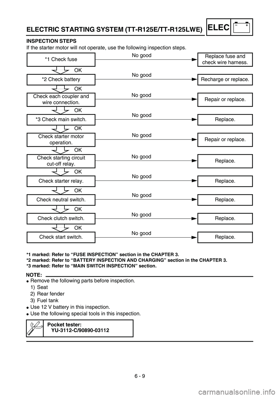
6 - 9 INSPECTION STEPS
If the starter motor will not operate, use the following inspection steps.
*1 marked: Refer to “FUSE INSPECTION” section in the CHAPTER 3.
*2 marked: Refer to “BATTERY INSPECTION AND CHARGING” section in the CHAPTER 3.
*3 marked: Refer to “MAIN SWITCH INSPECTION” section.
NOTE:
�Remove the following parts before inspection.
1) Seat
2) Rear fender
3) Fuel tank
�Use 12 V battery in this inspection.
�Use the following special tools in this inspection.
Pocket tester:
YU-3112-C/90890-03112
*1 Check fuseReplace fuse and
check wire harness.
*2 Check battery Recharge or replace.
Check each coupler and
wire connection.Repair or replace.
*3 Check main switch. Replace.
Check starter motor
operation.Repair or replace.
Check starting circuit
cut-off relay.Replace.
Check starter relay. Replace.
Check neutral switch. Replace.
Check clutch switch. Replace.
Check start switch. Replace.
OK
OK
OK
OK
OK
OK
OK
OK
OK
No good
No good
No good
No good
No good
No good
No good
No good
No good
No good
ELECTRIC STARTING SYSTEM (TT-R125E/TT-R125LWE)
Page 586 of 610

6 - 10
–+ELEC
EC624000
COUPLERS AND LEADS CONNECTION
INSPECTION
1. Check:
�Couplers and leads connection
Rust/dust/looseness/short-circuit →
Repair or replace.
STARTER MOTOR OPERATION
1. Connect the positive battery terminal 1
and starter motor lead 2 with a jumper
lead 3.
Not operate → Repair or replace the
starter motor.
WARNING
�A wire that is used as a jumper lead must
have at least the same capacity or more
as that of the a battery lead, otherwise the
jumper lead may burn.
�This check is likely to produce sparks,
therefore make sure nothing flammable is
in the vicinity.
STARTING CIRCUIT CUT-OFF RELAY
INSPECTION
1. Remove:
�Starting circuit cut-off relay
2. Inspect:
�Starting circuit cut-off relay conduct
Use 12 V battery.
Battery (+) lead → Sky blue lead 1
Battery (–) lead → Red/White lead 2
Tester (+) lead → Red/White lead 3
Tester (–) lead → Red/White lead 4
R/W
3R/W
4Tester selec-
tor position
Connected
to battery
Ω × 1Not
connected
to battery
2 4
3
1
ELECTRIC STARTING SYSTEM (TT-R125E/TT-R125LWE)
Page 588 of 610
6 - 11
–+ELEC
STARTER RELAY INSPECTION
1. Remove:
�Starter relay
2. Inspect:
�Starter relay conduct
Use 12 V battery.
Continuous while not connected to the battery
→ Replace.
Not continuous while connected to the battery
→ Replace.Battery (+) lead →
Starter relay terminal 1
Battery (–) lead →
Starter relay terminal 2
Tester (+) lead →
Starter relay terminal 3
Tester (–) lead →
Starter relay terminal 4
Ter-
minal
3
Ter-
minal
4Tester selec-
tor position
Connected
to battery
Ω × 1Not
connected
to battery
NEUTRAL SWITCH INSPECTION
1. Inspect:
�Neutral switch conduct
No continuous while in neutral → Replace.
Continuous while in gear → Replace. Tester (+) lead → Sky blue lead 1
Tester (–) lead → Black lead 2
Sb
1B
2Tester selec-
tor position
NEU-
TRAL
Ω × 1
IN
GEAR
WSb
YB
1
2
ELECTRIC STARTING SYSTEM (TT-R125E/TT-R125LWE)
Page:
< prev 1-8 9-16 17-24