Page 93 of 610
 SPEC
2 - 20
MAINTENANCE SPECIFICATIONS
Drive chain:
Type/manufacturer DID428HD/DAIDO ----
Number of links 122 links ----
Chain slack 35 ~ 50 mm (1.4 ~ 2.0 in) ----
Chain length (10 links) ----121.4 mm")
SPEC
2 - 20
MAINTENANCE SPECIFICATIONS
Drive chain:
Type/manufacturer DID428HD/DAIDO ----
Number of links 122 links ----
Chain slack 35 ~ 50 mm (1.4 ~ 2.0 in) ----
Chain length (10 links) ----121.4 mm
(4.78 in)
Front disc brake:
Disc outside dia. × Thickness 220 × 3.0 mm (8.66 × 0.12 in)220 × 2.5 mm
(8.66 × 0.10 in)
Deflection limit ----0.15 mm (0.006 in)
Pad thickness 4.0 mm (0.16 in)0.8 mm (0.03 in)
Master cylinder inside dia. 11.0 mm (0.433 in) ----
Caliper cylinder inside dia. 22.22 mm (0.875 in) × 2 ----
Brake fluid type DOT #4 ----
Rear drum brake:
Drum brake type Leading, trailing ----
Drum inside diameter 110 mm (4.33 in) 111 mm (4.37 in)
Lining thickness 4.0 mm (0.16 in) 2.0 mm (0.08 in)
Shoe spring free length 50.5 mm (1.99 in) ----
Brake lever and brake pedal:
Brake lever free play (lever end) 2 ~ 5 mm (0.08 ~ 0.20 in) ----
Brake pedal position
(vertical height below footrest top)1 mm (0.04 in) ----
Brake pedal free play 20 ~ 30 mm (0.79 ~ 1.18 in) ----
Clutch lever free play (lever end) 10 ~ 15 mm (0.39 ~ 0.59 in) ----
Throttle grip free play 3 ~ 5 mm (0.12 ~ 0.20 in) ----Item Standard Limit
Page 97 of 610
 SPEC
2 - 24
MAINTENANCE SPECIFICATIONS
TT-R125E/TT-R125LWE
Item Standard Limit
CDI:
Magneto-model/manufacturer 5HP-10/YAMAHA ----
Source coil resistance (color) 688 ~ 1,032 Ω at 20 ˚C (68 ˚F)
(Bro")
SPEC
2 - 24
MAINTENANCE SPECIFICATIONS
TT-R125E/TT-R125LWE
Item Standard Limit
CDI:
Magneto-model/manufacturer 5HP-10/YAMAHA ----
Source coil resistance (color) 688 ~ 1,032 Ω at 20 ˚C (68 ˚F)
(Brown – Green)----
Pickup coil resistance (color) 248 ~ 372 Ω at 20 ˚C (68 ˚F)
(Red – White)----
CDI unit-model/manufacturer 5HP-00/YAMAHA ----
Ignition coil:
Model/manufacturer 4KJ-10/YAMAHA ----
Minimum spark gap 6 mm (0.24 in) ----
Primary winding resistance 0.18 ~ 0.28 Ω at 20 ˚C (68 ˚F) ----
Secondary winding resistance 6.3 ~ 9.5 kΩ at 20 ˚C (68 ˚F) ----
Spark plug cap:
Type Resin ----
Resistance 10 kΩ at 20 ˚C (68 ˚F) ----
Charging system:
System type CDI magneto ----
Model/manufacturer 5HP-10/YAMAHA ----
Normal output 14 V/100 W at 5,000 r/min ----
Charging coil resistance (color) 0.64 ~ 0.96 Ω at 20 ˚C (68 ˚F)
(White – Black)----
Lighting coil resistance (color) 0.52 ~ 0.78 Ω at 20 ˚C (68 ˚F)
(Yellow – Black)----
Rectifier/regulator:
Regulator type Semiconductor short circuit ----
Model/manufacture SH620B-12/SHINDENGEN ----
No-load regulated voltage 14.0 ~ 15.0 V ----
Rectifier capacity 8 A ----
Electric starting system:
Type Constant mesh ----
Starter motor:
Model/manufacturer 5HP00/YAMAHA ----
Operation voltage 12 V ----
Output 0.25 kW ----
Armature coil resistance 0.017 ~ 0.021 Ω at 20 ˚C (68 ˚F) ----
Brush overall length 10 mm (0.40 in) 3.5 mm
(0.14 in)
Brush quantity 2 pcs. ----
Spring force 5.52 ~ 8.28 N
(560 ~ 840 g, 19.8 ~ 29.7 oz)----
Commutator diameter 22 mm (0.9 in) 21 mm
(0.8 in)
Mica undercut (depth) 1.5 mm (0.06 in) ----
Page 99 of 610
 SPEC
2 - 26
EC220001
GENERAL TORQUE SPECIFICATIONS
This chart specifies torque for standard fasten-
ers with standard I.S.O. pitch threads. Torque
specifications for special components or
assemblies a")
SPEC
2 - 26
EC220001
GENERAL TORQUE SPECIFICATIONS
This chart specifies torque for standard fasten-
ers with standard I.S.O. pitch threads. Torque
specifications for special components or
assemblies are included in the applicable sec-
tions of this book. To avoid warpage, tighten
multi-fastener assemblies in a crisscross fash-
ion, in progressive stages, until full torque is
reached. Unless otherwise specified, torque
specifications call for clean, dry threads. Com-
ponents should be at room temperature.
A: Distance between flats
B: Outside thread diameter
EC230000
DEFINITION OF UNITS
A
(Nut)B
(Bolt)TORQUE
SPECIFICATION
Nm m•kg ft•lb
10 mm
12 mm
14 mm
17 mm
19 mm
22 mm6 mm
8 mm
10 mm
12 mm
14 mm
16 mm6
15
30
55
85
1300.6
1.5
3.0
5.5
8.5
134.3
11
22
40
61
94
Unit Read Definition Measure
mm
cmmillimeter
centimeter10
-3 meter
10-2 meterLength
Length
kg kilogram 10
3 gram Weight
N Newton 1 kg
× m/sec2Force
Nm
m • kgNewton meter
Meter kilogramN
× m
m
× kgTorque
Torque
Pa Pascal N/m
2Pressure
N/mm Newton per millimeter N/mm Spring rate
L
cm
3Liter
Cubic centimeter—
—Volume or capacity
Volume or capacity
r/min Revolution per minute—Engine speed
GENERAL TORQUE SPECIFICATIONS/
DEFINITION OF UNITS
Page 214 of 610
3 - 21
INSP
ADJ
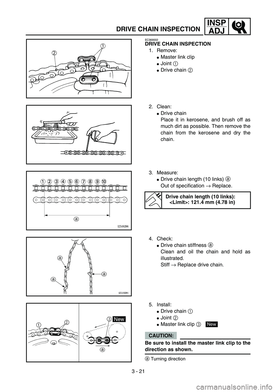
DRIVE CHAIN INSPECTION
EC369002
DRIVE CHAIN INSPECTION
1. Remove:
�Master link clip
�Joint 1
�Drive chain 2
2. Clean:
�Drive chain
Place it in kerosene, and brush off as
much dirt as possible. Then remove the
chain from the kerosene and dry the
chain.
3. Measure:
�Drive chain length (10 links) a
Out of specification → Replace.
Drive chain length (10 links):
: 121.4 mm (4.78 in)
4. Check:
�Drive chain stiffness a
Clean and oil the chain and hold as
illustrated.
Stiff → Replace drive chain.
5. Install:
�Drive chain 1
�Joint 2
�Master link clip 3
CAUTION:
Be sure to install the master link clip to the
direction as shown.
aTurning direction
New
Page 220 of 610
 3 - 24
INSP
ADJ
REAR SHOCK ABSORBER ASSEMBLY
INSPECTION
1. Inspect:
�Swingarm smooth action
Abnormal noise/unsmooth action →
Grease the pivoting points or repair the
pivoting points.
Damage/oil lea")
3 - 24
INSP
ADJ
REAR SHOCK ABSORBER ASSEMBLY
INSPECTION
1. Inspect:
�Swingarm smooth action
Abnormal noise/unsmooth action →
Grease the pivoting points or repair the
pivoting points.
Damage/oil leakage → Replace.
REAR SHOCK ABSORBER SPRING
PRELOAD ADJUSTMENT
1. Elevate the rear wheel by placing the
suitable stand under the engine.
2. Remove:
�Left side cover
3. Loosen:
�Locknut 1
4. Adjust:
�Spring preload
By turning the adjuster 2.
NOTE:
�Be sure to remove all dirt and mud from
around the locknut and adjuster before
adjustment.
�The length of the spring (installed) changes
1.5 mm (0.06 in) per turn of the adjuster.
CAUTION:
Never attempt to turn the adjuster beyond
the maximum or minimum setting.Stiffer →Increase the spring preload.
(Turn the adjuster 2 in.)
Softer →Decrease the spring preload.
(Turn the adjuster 2 out.)
Spring length (installed) a:
Standard length Extent of adjustment
TT-R125/TT-R125E/
TT-R125LW:
165 mm
(6.50 in)
TT-R125LWE:
160.5 mm
(6.32 in)TT-R125/TT-R125E/
TT-R125LW:
155 ~ 175 mm
(6.10 ~ 6.89 in)
TT-R125LWE:
147.5 ~ 167.5 mm
(5.81 ~ 6.59 in)
REAR SHOCK ABSORBER ASSEMBLY INSPECTION/
REAR SHOCK ABSORBER SPRING PRELOAD ADJUSTMENT
Page 300 of 610
4 - 21
ENGCAMSHAFT AND ROCKER ARMS
REMOVAL POINTS
Rocker arm shaft
1. Remove:
�Rocker arm shafts
NOTE:
Use a slide hammer bolt 1 and weight 2 to
slide out the rocker arm shafts.
Small slide hammer set:
YU-1083-A
Slide hammer bolt:
90890-01085
Weight:
90890-01084
Camshaft
1. Remove:
�Camshaft 1
�Camshaft bearing 2
NOTE:
Screw in a suitable length of 8 mm bolt 3 into
the threaded end of the camshaft and pull out
the camshaft.
INSPECTION
Camshaft
1. Inspect:
�Cam lobes
Pitting/scratches/blue discoloration →
Replace.
2. Measure:
�Cam lobes length a and b
Out of specification → Replace.
Cam lobes length limit:
Intake:
a 25.851 mm (1.0178 in)
b 21.165 mm (0.8333 in)
Exhaust:
a 25.811 mm (1.0162 in)
b 21.020 mm (0.8276 in)
Page 316 of 610
 4 - 29
ENGVALVES AND VALVE SPRINGS
�Install the valve into the cylinder head.
�Turn the valve until the valve face and
valve seat are evenly polished, then clean
off all of the compound.
NOTE:
For bes")
4 - 29
ENGVALVES AND VALVE SPRINGS
�Install the valve into the cylinder head.
�Turn the valve until the valve face and
valve seat are evenly polished, then clean
off all of the compound.
NOTE:
For best lapping results, lightly tap the valve
seat while rotating the valve back and forth
between your hands.
�Apply a fine lapping compound to the
valve face and repeat the above steps.
NOTE:
After every lapping operation be sure to
clean off all of the compound from the valve
face and valve seat.
�Apply Mechanic’s blueing dye (Dykem) to
the valve face.
�Install the valve into the cylinder head.
�Press the valve through the valve guide
and onto the valve seat to make a clear
pattern.
�Measure the valve seat width again. If the
valve seat width is out of specification,
reface and re-lap the valve seat.
Valve spring
1. Measure:
�Valve spring free length a
Out of specification → Replace.
Free length (valve spring):
Intake:
32.55 mm (1.28 in)
: 31.2 mm (1.23 in)
Exhaust:
32.55 mm (1.28 in)
: 31.2 mm (1.23 in)
Page 318 of 610
4 - 30
ENGVALVES AND VALVE SPRINGS
2. Measure:
�Compressed spring force a
Out of specification → Replace.
bInstalled length
3. Measure:
�Spring tilt a
Out of specification → Replace.
Compressed spring force:
Intake:
14.0 ~ 16.1 kg at 25.6 mm
(30.86 ~ 35.49 lb at 1.01 in)
Exhaust:
14.0 ~ 16.1 kg at 25.6 mm
(30.86 ~ 35.49 lb at 1.01 in)
Spring tilt limit:
Intake:
2.5˚/1.4 mm (0.06 in)
Exhaust:
2.5˚/1.4 mm (0.06 in)
ASSEMBLY AND INSTALLATION
Valve
1. Apply:
�Molybdenum disulfide oil
(onto the valve stem and valve stem
seal)
2. Install:
�Valve spring seats 1
�Valve stem seals 2
�Valves 3
�Valve springs 4
�Valve spring retainers 5
NOTE:
�Make sure that each valve is installed in its
original place.
�Install the valve springs with the larger pitch
a facing upwards.
bSmaller pitch
New