Page 354 of 610
 4 - 48
ENGCLUTCH AND PRIMARY DRIVEN GEAR
9. Adjust:
�Push lever position
10. Install:
�Dowel pins
�Gasket (right crankcase cover)
�Right crankcase cover
�Negative battery lead
(TT-R125E/TT-R125LWE)")
4 - 48
ENGCLUTCH AND PRIMARY DRIVEN GEAR
9. Adjust:
�Push lever position
10. Install:
�Dowel pins
�Gasket (right crankcase cover)
�Right crankcase cover
�Negative battery lead
(TT-R125E/TT-R125LWE) 1
�Lead holder
(TT-R125E/TT-R125LWE) 2
�Bolts (right crankcase cover)
NOTE:
�Apply Quick gasket® (YAMAHA Bond
No.1215) to end of the right crankcase cover
bolts, as shown.
�Tighten the bolts in stages, using a criss-
cross pattern. Adjustment steps:
�Loosen the locknut 1.
�Turn the push rod 1 2 clockwise or coun-
terclockwise to match alignment marks.
�Hold the push rod 1 to prevent it from
moving and tighten the locknut to specifi-
cation.
�Tighten the locknut 1.
T R..
Locknut:
8 Nm (0.8 m • kg, 5.8 ft • lb)
Quick gasket®:
ACC-QUICK-GS-KT
YAMAHA Bond No.1215:
90890-85505
New
T R..10 Nm (1.0 m · kg, 7.2 ft · lb)
11. Install:
�Kickstarter crank 1
�Nut (kickstarter crank) 2
NOTE:
Install the kickstarter crank so that there is 5 ~
10 mm (0.2 ~ 0.4 in) a between the kickstarter
crank and the right crankcase cover.
T R..50 Nm (5.0 m · kg, 36 ft · lb)
Page 370 of 610
4 - 56
ENGKICK AXLE AND SHIFT SHAFT
Shift shaft
1. Install:
�Shift shaft 1
NOTE:
�Apply the lithium soap base grease on the oil
seal lip of the left crankcase side.
�Hook the spring ends onto the stopper 2.
Kick axle assembly
1. Install:
�Kickstarter segment gear 1
�Plain washer 2
�Torsion spring 3
On kick axle 4.
NOTE:
Make sure the stopper a of the torsion spring
fits into the hole b on the kick axle.
2. Install:
�Spring guide 1
NOTE:
Slide the spring guide into the kick axle, make
sure the groove a in the spring guide fits on
the stopper of the torsion spring.
3. Install:
�Kick axle assembly 1
NOTE:
�Apply the engine oil on the kick axle.
�Slide the kick axle assembly into the crank-
case, make sure the clip 2 and kick axle
stopper b fit into their home positions a, c.
4. Hook:
�Torsion spring 1
NOTE:
Turn the torsion spring clockwise and hook
into the proper hole a in the crankcase.
Page 384 of 610
 4 - 63
ENG
CDI MAGNETO AND STARTER CLUTCH
(TT-R125E/TT-R125LWE)
3. Check:
�Starter clutch operation
�Install the starter clutch drive gear 1 onto
the starter clutch 2 and hold the starter
clutch.
�Whe")
4 - 63
ENG
CDI MAGNETO AND STARTER CLUTCH
(TT-R125E/TT-R125LWE)
3. Check:
�Starter clutch operation
�Install the starter clutch drive gear 1 onto
the starter clutch 2 and hold the starter
clutch.
�When turning the starter clutch drive gear
counterclockwise ı, the starter clutch and
the starter clutch drive gear should
engage. If the starter clutch drive gear and
starter clutch do not engage, the starter
clutch is faulty and must be replaced.
�When turning the starter clutch drive gear
clockwise Å, it should turn freely.
If the starter clutch drive gear does not
turn freely, the starter clutch is faulty and
must be replaced.
Å
ı
1
2
EC4L5000
ASSEMBLY AND INSTALLATION
CDI magneto
1. Install:
�Stator 1
�Bolt (stator)
�Lead guide
�Screw (lead guide) 2
�Pickup coil 3
�Bolt (pickup coil)
T R..10 Nm (1.0 m · kg, 7.2 ft · lb)LT
T R..7 Nm (0.7 m · kg, 5.1 ft · lb)LT
T R..10 Nm (1.0 m · kg, 7.2 ft · lb)LT
2. Install:
�Stater idle gear 1
�Plate 2
�Bolt 3
�Washer 4
NOTE:
Apply the engine oil on the starter idle gear
inner circumference.
4
1
2
3
ET R..7 Nm (0.7 m · kg, 5.1 ft · lb)
Page 452 of 610
 5 - 14
CHASFRONT BRAKE (TT-R125LW/TT-R125LWE)
REMOVAL POINTS
Brake fluid
1. Remove:
�Brake master cylinder cap 1
NOTE:
Do not remove the diaphragm.
2. Connect the transparent hose 2 to the
bleed scre")
5 - 14
CHASFRONT BRAKE (TT-R125LW/TT-R125LWE)
REMOVAL POINTS
Brake fluid
1. Remove:
�Brake master cylinder cap 1
NOTE:
Do not remove the diaphragm.
2. Connect the transparent hose 2 to the
bleed screw 1 and place a suitable con-
tainer under its end.
3. Loosen the bleed screw and drain the
brake fluid while pulling in the lever.
CAUTION:
�Do not reuse the drained brake fluid.
�Brake fluid may erode painted surfaces or
plastic parts. Always clean up spilled
fluid immediately.
Brake caliper
1. Remove:
�Brake caliper 1
NOTE:
Turn the brake caliper counterclockwise and
pull out it from the guide pin 2 on the brake
caliper bracket.
Brake caliper piston
1. Remove:
�Brake caliper piston
Use compressed air and proceed care-
fully.
WARNING
�Cover piston with rag and use extreme
caution when expelling piston from cylin-
der.
�Never attempt to pry out piston.
Brake caliper piston removal steps:
�Insert a piece of rag into the brake caliper
to lock one brake caliper.
�Carefully force the piston out of the brake
caliper cylinder with compressed air.
Page 460 of 610
5 - 18
CHASFRONT BRAKE (TT-R125LW/TT-R125LWE)
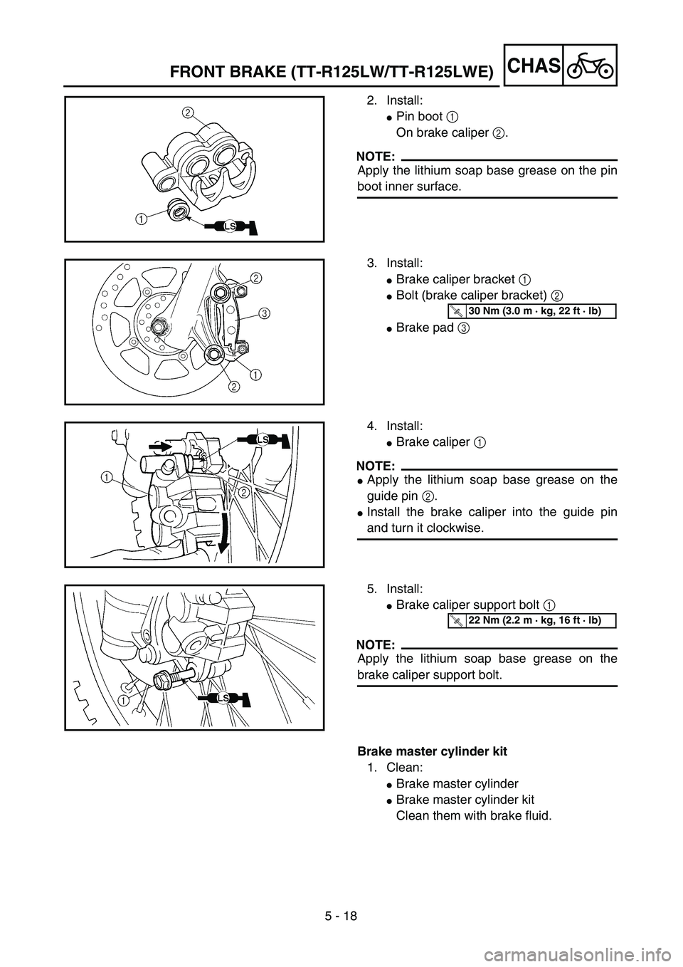
2. Install:
�Pin boot 1
On brake caliper 2.
NOTE:
Apply the lithium soap base grease on the pin
boot inner surface.
3. Install:
�Brake caliper bracket 1
�Bolt (brake caliper bracket) 2
�Brake pad 3
T R..30 Nm (3.0 m · kg, 22 ft · lb)
4. Install:
�Brake caliper 1
NOTE:
�Apply the lithium soap base grease on the
guide pin 2.
�Install the brake caliper into the guide pin
and turn it clockwise.
5. Install:
�Brake caliper support bolt 1
NOTE:
Apply the lithium soap base grease on the
brake caliper support bolt.
T R..22 Nm (2.2 m · kg, 16 ft · lb)
Brake master cylinder kit
1. Clean:
�Brake master cylinder
�Brake master cylinder kit
Clean them with brake fluid.