Page 16 of 479
’04 TUNDRA_U (L/O 0309)
7
2004 TUNDRA from Sep. ’03 Prod. (OM34426U)
1. Side vents
2. Instrument cluster
3. Center vents
4. Multi −information display
5. Personal lights
6. Auxiliary box
7. Electric moon roof switches
8. Side defroster outlet
9. Glove box
10. Power door lock switches
11. Power window switches
12. Power outlets
13. Seat heater switches
14. Rear console box
15. Input terminal adapter
16. Headphone input jacks and headphone volume control dials
17. Cup holders
18. Lower vent
19. Hood lock release lever
20. Parking brake pedal
21. Window lock switch
Instrument panel overview (double cab models)
Page 24 of 479

’04 TUNDRA_U (L/O 0309)
15
2004 TUNDRA from Sep. ’03 Prod. (OM34426U)
OPERATION OF INSTRUMENTS AND
CONTROLS
Keys and Doors
Keys 16
. . . . . . . . . . . . . . . . . . . . . . . . . . . . . . . . . . . . .\
. . . . . . . . . . . . . . . . . .
Front doors 16
. . . . . . . . . . . . . . . . . . . . . . . . . . . . . . . . . . . . \
. . . . . . . . . . . . .
Side doors 18
. . . . . . . . . . . . . . . . . . . . . . . . . . . . . . . . . . . . \
. . . . . . . . . . . . . .
Access doors 20
. . . . . . . . . . . . . . . . . . . . . . . . . . . . . . . . . . . . \
. . . . . . . . . . .
Wireless remote control system 21
. . . . . . . . . . . . . . . . . . . . . . . . . . . . . . .
Power windows 31
. . . . . . . . . . . . . . . . . . . . . . . . . . . . . . . . . . . . \
. . . . . . . . . .
Rear side windows 34
. . . . . . . . . . . . . . . . . . . . . . . . . . . . . . . . . . . . \
. . . . . . .
Rear window 34
. . . . . . . . . . . . . . . . . . . . . . . . . . . . . . . . . . . . \
. . . . . . . . . . . .
Power rear window 35
. . . . . . . . . . . . . . . . . . . . . . . . . . . . . . . . . . . . \
. . . . . .
Tailgate 36
. . . . . . . . . . . . . . . . . . . . . . . . . . . . . . . . . . . . \
. . . . . . . . . . . . . . . . .
Hood 38
. . . . . . . . . . . . . . . . . . . . . . . . . . . . . . . . . . . . \
. . . . . . . . . . . . . . . . . . .
Toyota vehicle intrusion protection system (TVIP) 39
. . . . . . . . . . . . . . .
Theft deterrent system 40
. . . . . . . . . . . . . . . . . . . . . . . . . . . . . . . . . . . . \
. . .
Fuel tank cap 42
. . . . . . . . . . . . . . . . . . . . . . . . . . . . . . . . . . . . \
. . . . . . . . . . .
Electric moon roof 44
. . . . . . . . . . . . . . . . . . . . . . . . . . . . . . . . . . . . \
. . . . . . .
SECTION 1� 2
Page 52 of 479
’04 TUNDRA_U (L/O 0309)
43
2004 TUNDRA from Sep. ’03 Prod. (OM34426U)
Ty p e A
Ty p e B
1. To open the fuel filler door, pull the
door toward out as shown.
When refueling, turn off the engine.
CAUTION
�Do not smoke, cause sparks or al-
low open flames when refueling.
The fumes are flammable.
�When opening the cap, do not re-
move the cap quickly. In hot weath-
er, fuel under pressure could cause
injury by spraying out of the filler
neck if the cap is suddenly re-
moved.
�Do not fill a fuel container on a
plastic truck bed liner, a rubber
truck bed mat, or any other insulat-
ing material. A static electricity
charge could cause a spark and fire
hazard. The proper procedure is to
place an approved fuel container on
the ground away from the truck for
filling.
Ty p e A
Ty p e B
Page 53 of 479

’04 TUNDRA_U (L/O 0309)
44
2004 TUNDRA from Sep. ’03 Prod. (OM34426U)
2. To remove the fuel tank cap, turn
the cap counterclockwise by 90 de-
grees (to the pressure point 1), and
then turn it an additional 30 degrees
(to point 2). Pause slightly before
removing it.
It is not unusual to hear a slight swoosh
when the cap is opened.
When installing the cap, turn the cap
clockwise until you hear a click. When
you hear the click, the cap is fully
closed.
If the cap is not tightened securely, the
malfunction indicator lamp comes on.
Make sure the cap is tightened securely.
The indicator lamp goes off after driving
several times. If the indicator lamp does
not go off, contact your Toyota dealer as
soon as possible.CAUTION
�Make sure the cap is tightened se-
curely to prevent fuel sp illage in
the event of an accident.
�Use only a genuine Toyota fuel tank
cap for replacement. It is designed
to regulate fuel tank pressure.
NOTICE
To prevent damage to the cap, apply
force only in the turning direction to
the cap. Do not pull or pry it.Sliding operation
Tilting operation
Electric moon roof
Page 166 of 479

’04 TUNDRA_U (L/O 0309)
157
2004 TUNDRA from Sep. ’03 Prod. (OM34426U)
The light may occasionally flicker when
the engine is idling or it may come on
briefly after a hard stop. There is no
cause for concern if it then goes out when
the engine is accelerated slightly.
The light may come on when the oil level
is extremely low. It is not designed to
indicate low oil level, and the oil level
must be checked using the level dipstick.
NOTICE
Do not drive the vehicle with the
warning light on—even for one block.
It may ruin the engine.
(f) Malfunction Indicator Lamp
This lamp comes on when the ignition
key is turned to the “ON” position and
goes off after the engine starts. This
means that the warning light system is
operating properly.
If the lamp remains on, or the lamp
comes on while driving, first check the
followings.
�Empty fuel tank
If the fuel tank is empty, refuel immedi-
ately.
�Loose fuel tank cap
If the fuel tank cap is loose, securely
tighten it.
These cases are temporary malfunctions.
The malfunction indicator lamp will go off
after taking several driving trips.
If the lamp will not go off even after the
several trips, contact your Toyota dealer
as soon as possible. If the fuel tank is not empty or the fuel
tank cap is not loose...
�There is a problem somewhere in the
engine, emission control system, elec-
tronic throttle control system, automatic
transmission electrical system or warn-
ing light system itself.
Contact your Toyota dealer as soon as
possible to service the vehicle.
5VZ− FE engine—
If the engine speed does not increase with
the accelerator pedal depressed down to
about the middle position, there may be
a problem somewhere in your electronic
throttle control system.
At this time, if you depress the accelera-
tor pedal more firmly and slowly, you can
drive your vehicle at low speeds. Have
your vehicle checked by your Toyota deal-
er as soon as possible.
Even if the abnormality of the electronic
throttle control system is corrected during
low speed driving, the system may not be
recovered until the engine is stopped and
the ignition key is turned to “ACC” or
“LOCK” position.
Page 224 of 479
’04 TUNDRA_U (L/O 0309)
215
2004 TUNDRA from Sep. ’03 Prod. (OM34426U)
The rear seat audio system consists of
following components.
1. Front audio system
2. Rear seat audio system display
3. Rear seat audio system controller
4. Headphone volume control dials
5. Headphone input jacks
6. Controller holder The rear seat audio system can be oper-
ated with the rear seat audio system con-
troller.
CAUTION
Do not disassemble or modify the
controller. It may cause an accident,
fire or electric shock.
NOTICE
Keep the controller away from direct
sunlight, high heat and high humidity.
These conditions could cause the
case to deform or the battery to ex-
plode or leak.
—Rear seat audio system
controller
Page 235 of 479

’04 TUNDRA_U (L/O 0309)
226
2004 TUNDRA from Sep. ’03 Prod. (OM34426U)
NOTICE
�The screen should be cleaned with
a dry soft cloth. If the screen is
pushed by hand or wiped with a
hard cloth, the surface of the
screen may be scratched.
� Benzene or alkaline solutions may
damage the coated surface of the
screen .
� To prevent the battery from being
discharged, do not turn on the rear
seat entertainment system longer
than necessary when the engine is
not running.
The rear seat entertainment system can
be operated with the rear seat entertain-
ment system controller. The system can-
not be operated by touching the switches
on the screen directly.
CAUTION
Do not disassemble or modify the
controller. It may cause an accident,
fire or electric shock.
NOTICE
Keep the controller away from direct
sunlight, high heat and high humidity.
These conditions could cause the
case to deform or the battery to ex-
plode or leak.BEFORE USING THE CONTROLLER
(for new vehicle owners)
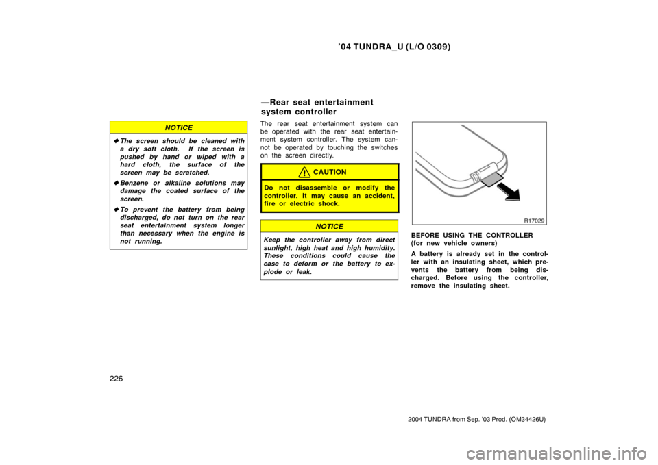
A battery is already set in the control-
ler with an insulating sheet, which pre-
vents the battery from being dis-
charged. Before using the controller,
remove the insulating sheet.
—Rear seat entertainment
system controller
Page 277 of 479

’04 TUNDRA_U (L/O 0309)
268
2004 TUNDRA from Sep. ’03 Prod. (OM34426U)
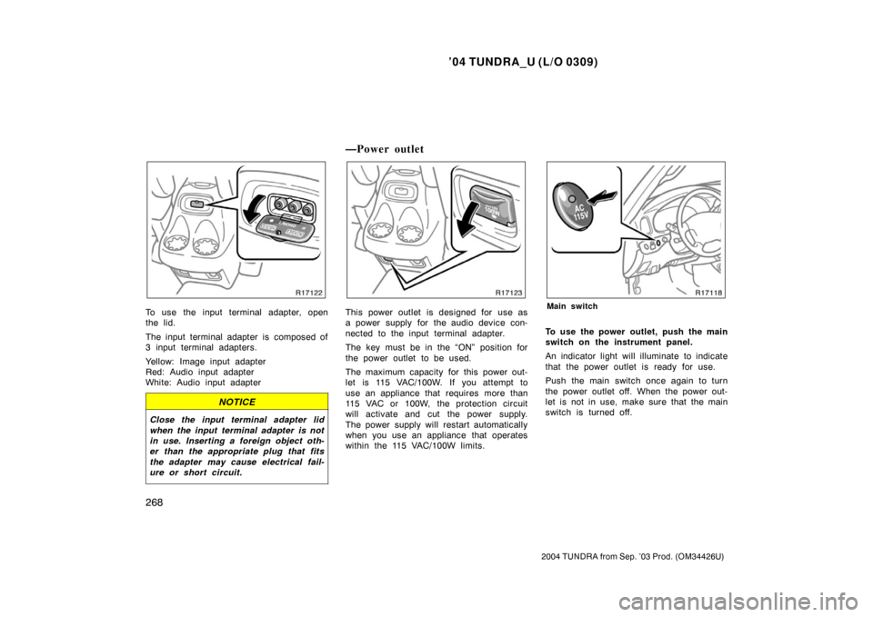
To use the input terminal adapter, open
the lid.
The input terminal adapter is composed of
3 input terminal adapters.
Yellow: Image input adapter
Red: Audio input adapter
White: Audio input adapter
NOTICE
Close the input terminal adapter lid
when the input terminal adapter is not
in use. Inserting a foreign object oth-
er than the appropriate plug that fits
the adapter may cause electrical fail-
ure or short circuit.
—Power outlet
This power outlet is designed for use as
a power supply for the audio device con-
nected to the input terminal adapter.
The key must be in the “ON” position for
the power outlet to be used.
The maximum capacity for this power out-
let is 115 VAC/100W. If you attempt to
use an appliance that requires more than
115 VAC or 100W, the protection circuit
will activate and cut the power supply.
The power supply will restart automatically
when you use an appliance that operates
within the 115 VAC/100W limits.Main switch
To use the power outlet, push the main
switch on the instrument panel.
An indicator light will illuminate to indicate
that the power outlet is ready for use.
Push the main switch once again to turn
the power outlet off. When the power out-
let is not in use, make sure that the main
switch is turned off.