2004 SUZUKI SWIFT engine type
[x] Cancel search: engine typePage 10 of 1496
Downloaded from www.Manualslib.com manuals search engine 00-5 Precautions:
• When performing service to electrical parts that does not require use of battery power, disconnect the
negative cable of the battery.
• When disconnecting the negative cable from the battery, be careful to the following.
– Check and record DTCs in ECM and HVAC control module if necessary before disconnecting.
– Record displayed contents of the clock and/or audio system, etc. before disconnecting and reset it
as before after connecting.
– For vehicle equipped with electric throttle body system, perform electric throttle body system
calibration referring to “Electric Throttle Body
System Calibration in Section 1C” after
reconnecting the negative cable to the battery.
– For vehicle equipped with ESP ®, calibrate steering
angle sensor referring to “Sensor Calibration in
Section 4F” after reconnecting the negative cable
to the battery.
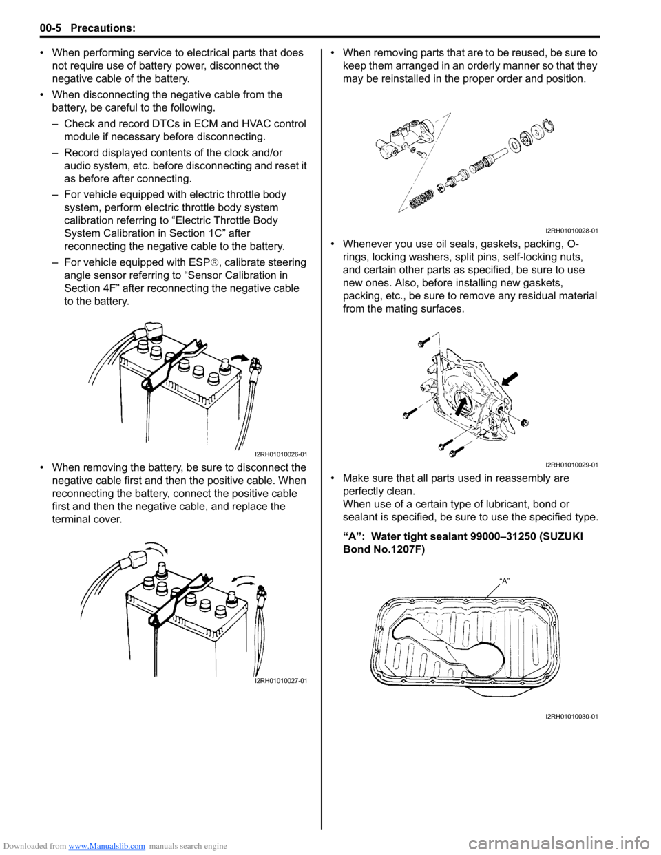
• When removing the battery, be sure to disconnect the negative cable first and then the positive cable. When
reconnecting the battery, connect the positive cable
first and then the negative cable, and replace the
terminal cover. • When removing parts that are to be reused, be sure to
keep them arranged in an orderly manner so that they
may be reinstalled in the proper order and position.
• Whenever you use oil seals, gaskets, packing, O- rings, locking washers, split pins, self-locking nuts,
and certain other parts as specified, be sure to use
new ones. Also, before installing new gaskets,
packing, etc., be sure to remove any residual material
from the mating surfaces.
• Make sure that all parts used in reassembly are perfectly clean.
When use of a certain type of lubricant, bond or
sealant is specified, be sure to use the specified type.
“A”: Water tight sealant 99000–31250 (SUZUKI
Bond No.1207F)
I2RH01010026-01
I2RH01010027-01
I2RH01010028-01
I2RH01010029-01
I2RH01010030-01
Page 14 of 1496
Downloaded from www.Manualslib.com manuals search engine 00-9 Precautions:
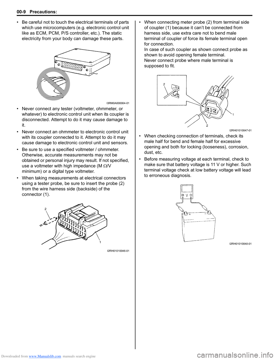
• Be careful not to touch the electrical terminals of parts which use microcomputers (e.g. electronic control unit
like as ECM, PCM, P/S controller, etc.). The static
electricity from your body can damage these parts.
• Never connect any tester (voltmeter, ohmmeter, or whatever) to electronic control unit when its coupler is
disconnected. Attempt to do it may cause damage to
it.
• Never connect an ohmmeter to electronic control unit with its coupler connected to it. Attempt to do it may
cause damage to electronic control unit and sensors.
• Be sure to use a specified voltmeter / ohmmeter. Otherwise, accurate measurements may not be
obtained or personal injury ma y result. If not specified,
use a voltmeter with high impedance (M Ω/V
minimum) or a digital type voltmeter.
• When taking measurements at electrical connectors using a tester probe, be sure to insert the probe (2)
from the wire harness side (backside) of the
connector (1). • When connecting meter probe (2) from terminal side
of coupler (1) because it can’t be connected from
harness side, use extra care not to bend male
terminal of coupler of force its female terminal open
for connection.
In case of such coupler as shown connect probe as
shown to avoid opening female terminal.
Never connect probe where male terminal is
supposed to fit.
• When checking connection of terminals, check its
male half for bend and female half for excessive
opening and both for locking (looseness), corrosion,
dust, etc.
• Before measuring voltage at each terminal, check to make sure that battery voltage is 11 V or higher. Such
terminal voltage check at lo w battery voltage will lead
to erroneous diagnosis.
I3RM0A000004-01
I2RH01010046-01
I2RH01010047-01
I2RH01010048-01
Page 19 of 1496
Downloaded from www.Manualslib.com manuals search engine Precautions: 00-14
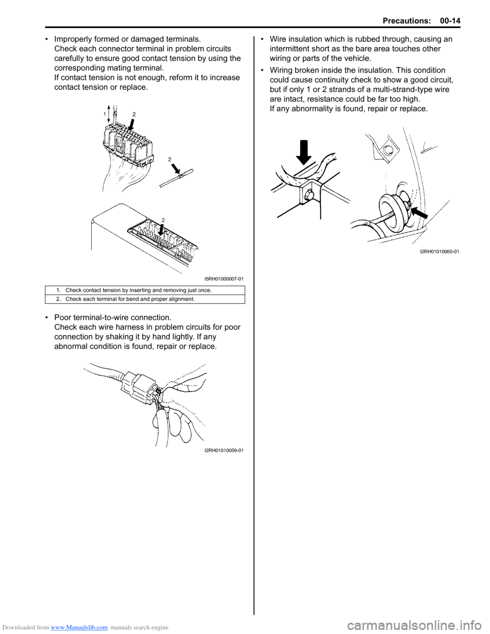
• Improperly formed or damaged terminals.Check each connector terminal in problem circuits
carefully to ensure good contact tension by using the
corresponding mating terminal.
If contact tension is not enough, reform it to increase
contact tension or replace.
• Poor terminal-to -wire connection.
Check each wire harness in problem circuits for poor
connection by shaking it by hand lightly. If any
abnormal condition is found, repair or replace. • Wire insulation which is rubbed through, causing an
intermittent short as the bare area touches other
wiring or parts of the vehicle.
• Wiring broken inside the insulation. This condition
could cause continuity check to show a good circuit,
but if only 1 or 2 strands of a multi-strand-type wire
are intact, resistance could be far too high.
If any abnormality is found, repair or replace.
1. Check contact tension by inserting and removing just once.
2. Check each terminal for bend and proper alignment.
I5RH01000007-01
I2RH01010059-01
I2RH01010060-01
Page 27 of 1496
Downloaded from www.Manualslib.com manuals search engine General Information: 0A-6
When Using Floor Jack
WARNING!
If the vehicle to be jacked up only at the front
or rear end, be sure to block the wheels on
ground in order to ensure safety.
After the vehicle is jacked up, be sure to
support it on stands. It is extremely
dangerous to do any work on the vehicle
raised on jack alone.
CAUTION!
• Never apply jack against rear suspension parts (i.e., stabilizer, etc.) or vehicle floor,
or it may get deformed.
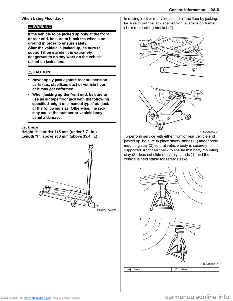
• When jacking up the front end, be sure to use an air type floor jack with the following
specified height or a manual type floor jack
of the following size. Otherwise, the jack
may cause the bumper or vehicle body
panel a damage.
Jack size
Height “h”: under 145 mm (under 5.71 in.)
Length “l”: above 900 mm (above 35.4 in.) In raising front or rear vehicl
e end off the floor by jacking,
be sure to put the jack a gainst front suspension frame
(1) or rear jacking bracket (2).
To perform service with either front or rear vehicle end
jacked up, be sure to place safety stands (1) under body
mounting stay (2) so that vehicle body is securely
supported. And then check to ensure that body mounting
stay (2) does not slide on safety stands (1) and the
vehicle is held stable for safety’s sake.
“h”
“l”
I4RS0A010002-01
[A]: Front
[B]: Rear
2
1
I4RS0A010003-01
1
1
2
2
[B] [A]
I4RS0A010004-01
Page 38 of 1496
Downloaded from www.Manualslib.com manuals search engine 0B-8 Maintenance and Lubrication:
Brake Fluid InspectionS7RS0B0206035
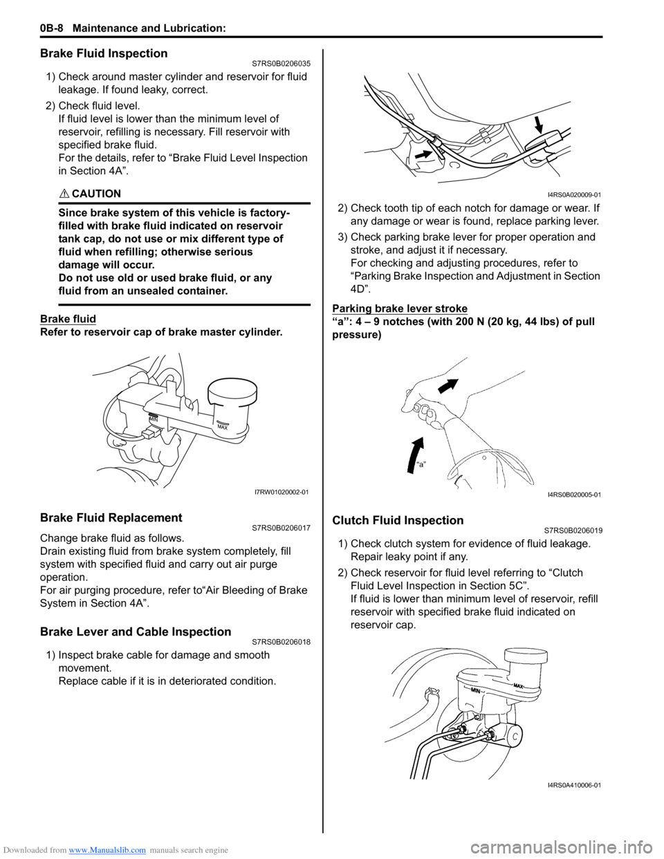
1) Check around master cylinder and reservoir for fluid leakage. If found leaky, correct.
2) Check fluid level. If fluid level is lower than the minimum level of
reservoir, refilling is necessary. Fill reservoir with
specified brake fluid.
For the details, refer to “Brake Fluid Level Inspection
in Section 4A”.
CAUTION!
Since brake system of this vehicle is factory-
filled with brake fluid indicated on reservoir
tank cap, do not use or mix different type of
fluid when refilling; otherwise serious
damage will occur.
Do not use old or used brake fluid, or any
fluid from an unsealed container.
Brake fluid
Refer to reservoir cap of brake master cylinder.
Brake Fluid ReplacementS7RS0B0206017
Change brake fluid as follows.
Drain existing fluid from brake system completely, fill
system with specified fluid and carry out air purge
operation.
For air purging procedure, refer to“Air Bleeding of Brake
System in Section 4A”.
Brake Lever and Cable InspectionS7RS0B0206018
1) Inspect brake cable for damage and smooth movement.
Replace cable if it is in deteriorated condition. 2) Check tooth tip of each notch for damage or wear. If
any damage or wear is found, replace parking lever.
3) Check parking brake lever for proper operation and stroke, and adjust it if necessary.
For checking and adjusting procedures, refer to
“Parking Brake Inspection and Adjustment in Section
4D”.
Parking brake lever stroke
“a”: 4 – 9 notches (with 200 N (20 kg, 44 lbs) of pull
pressure)
Clutch Fluid InspectionS7RS0B0206019
1) Check clutch system for evidence of fluid leakage. Repair leaky point if any.
2) Check reservoir for fluid level referring to “Clutch
Fluid Level Inspection in Section 5C”.
If fluid is lower than minimum level of reservoir, refill
reservoir with specified brake fluid indicated on
reservoir cap.
I7RW01020002-01
I4RS0A020009-01
I4RS0B020005-01
I4RS0A410006-01
Page 51 of 1496
Downloaded from www.Manualslib.com manuals search engine Engine General Information and Diagnosis: 1A-1
Engine
Engine General Information and Diagnosis
Precautions
Precautions on Engine ServiceS7RS0B1100001
CAUTION!
The following information on engine service
should be noted carefully, as it is important in
preventing damage, and in contributing to
reliable engine performance.
• When raising or supporting engine for any reason, do
not use a jack under oil pan. Due to small clearance
between oil pan and oil pump strainer, jacking against
oil pan may cause it to be bent against strainer,
resulting in damaged oil pick-up unit.
• It should be kept in mind , while working on engine,
that 12-volt electrical syste m is capable of violent and
damaging short circuits.
When performing any work where electrical terminals
can be grounded, ground cable of the battery should
be disconnected at battery.
• Any time the air cleaner, throttle body or intake manifold is removed, the intake opening should be
covered. This will protect against accidental entrance
of foreign material which could follow intake passage
into cylinder and cause extensive damage when
engine is started.
Precaution on On-Board Diagnostic (OBD)
System
S7RS0B1100005
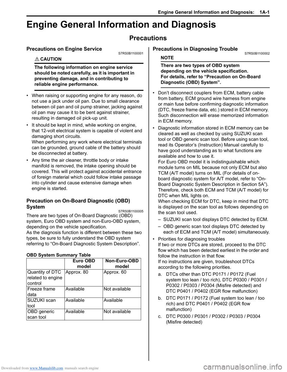
There are two types of On -Board Diagnostic (OBD)
system, Euro OBD system and non-Euro-OBD system,
depending on the vehicle specification.
As the diagnosis function is different between these two
types, be sure to fully understand the OBD system
referring to “On-Board Diagnostic System Description”.
OBD System Summary Table
Precautions in Diagnosing TroubleS7RS0B1100002
NOTE
There are two types of OBD system
depending on the vehicle specification.
For details, refer to “Precaution on On-Board
Diagnostic (OBD) System”.
• Don’t disconnect couplers from ECM, battery cable
from battery, ECM ground wire harness from engine
or main fuse before confirming diagnostic information
(DTC, freeze frame data, etc.) stored in ECM memory.
Such disconnection will erase memorized information
in ECM memory.
• Diagnostic information stored in ECM memory can be cleared as well as checke d by using SUZUKI scan
tool or OBD generic scan tool. Before using scan tool,
read its Operator’s (Instruction) Manual carefully to
have good understanding as to what functions are
available and how to use it.
For Euro OBD model it is indistinguishable which
module turns on MIL because not only ECM but also
TCM (A/T model) turns on MIL (For details of on-
board diagnostic system for A/T model, refer to “On-
Board Diagnostic System Description in Section 5A”).
Therefore, check both ECM and TCM (A/T model) for
DTC when MIL lights on.
When checking ECM for DTC, keep in mind that DTC
is displayed on the scan tool as follows depending on
the scan tool used.
– SUZUKI scan tool displays DTC detected by ECM.
– OBD generic scan tool displays DTC detected by each of ECM and TCM (A/T model) simultaneously.
• Priorities for diagnosing troubles If two or more DTCs are stored, proceed to the DTC
flow which has been detected earliest in the order and
follow the instructi on in that flow.
If no instructions are given, troubleshoot DTCs
according to the following priorities.
a. DTCs other than DTC P0171 / P0172 (Fuel system too lean / too rich), DTC P0300 / P0301 /
P0302 / P0303 / P0304 (Misfire detected) and
DTC P0401 / P0402 (EGR flow malfunction)
b. DTC P0171 / P0172 (Fuel system too lean / too rich) and DTC P0401 / P0402 (EGR flow
malfunction)
c. DTC P0300 / P0301 / P0302 / P0303 / P0304 (Misfire detected)
Euro OBD
model Non-Euro-OBD
model
Quantity of DTC
related to engine
control Approx. 80 Approx. 60
Freeze frame
data Available Not available
SUZUKI scan
tool Available Available
OBD generic
scan tool Available Not available
Page 53 of 1496
Downloaded from www.Manualslib.com manuals search engine Engine General Information and Diagnosis: 1A-3
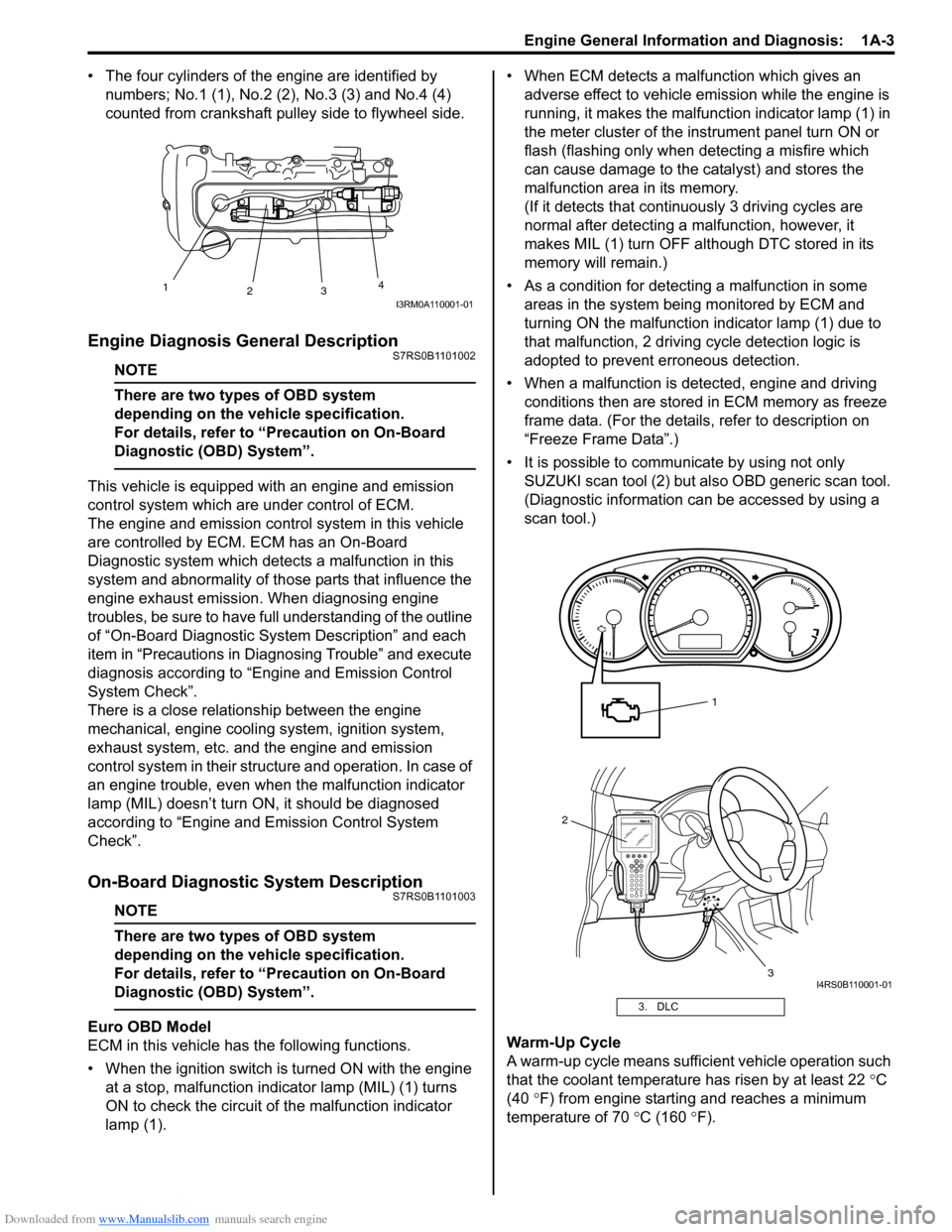
• The four cylinders of the engine are identified by numbers; No.1 (1), No.2 (2 ), No.3 (3) and No.4 (4)
counted from crankshaft pulley side to flywheel side.
Engine Diagnosis General DescriptionS7RS0B1101002
NOTE
There are two types of OBD system
depending on the vehicle specification.
For details, refer to “Precaution on On-Board
Diagnostic (OBD) System”.
This vehicle is equipped with an engine and emission
control system which are under control of ECM.
The engine and emission control system in this vehicle
are controlled by ECM. ECM has an On-Board
Diagnostic system which detects a malfunction in this
system and abnormality of those parts that influence the
engine exhaust emission. When diagnosing engine
troubles, be sure to have full understanding of the outline
of “On-Board Diagnostic System Description” and each
item in “Precautions in Diagnosing Trouble” and execute
diagnosis according to “Engine and Emission Control
System Check”.
There is a close relationship between the engine
mechanical, engine cooling system, ignition system,
exhaust system, etc. and the engine and emission
control system in their structure and operation. In case of
an engine trouble, even when the malfunction indicator
lamp (MIL) doesn’t turn ON, it should be diagnosed
according to “Engine and Emission Control System
Check”.
On-Board Diagnostic System DescriptionS7RS0B1101003
NOTE
There are two types of OBD system
depending on the vehicle specification.
For details, refer to “Precaution on On-Board
Diagnostic (OBD) System”.
Euro OBD Model
ECM in this vehicle has the following functions.
• When the ignition switch is turned ON with the engine at a stop, malfunction indicator lamp (MIL) (1) turns
ON to check the circuit of the malfunction indicator
lamp (1). • When ECM detects a malfunction which gives an
adverse effect to vehicle emission while the engine is
running, it makes the malfunction indicator lamp (1) in
the meter cluster of the inst rument panel turn ON or
flash (flashing only when detecting a misfire which
can cause damage to the catalyst) and stores the
malfunction area in its memory.
(If it detects that contin uously 3 driving cycles are
normal after detecting a malfunction, however, it
makes MIL (1) turn OFF although DTC stored in its
memory will remain.)
• As a condition for detecting a malfunction in some areas in the system being monitored by ECM and
turning ON the malfunction indicator lamp (1) due to
that malfunction, 2 driving cycle detection logic is
adopted to prevent erroneous detection.
• When a malfunction is detected, engine and driving conditions then are stored in ECM memory as freeze
frame data. (For the details, refer to description on
“Freeze Frame Data”.)
• It is possible to communicate by using not only SUZUKI scan tool (2) but also OBD generic scan tool.
(Diagnostic information can be accessed by using a
scan tool.)
Warm-Up Cycle
A warm-up cycle means sufficie nt vehicle operation such
that the coolant temperature has risen by at least 22 °C
(40 °F) from engine starting and reaches a minimum
temperature of 70 °C (160 ° F).
1
23 4
I3RM0A110001-01
3. DLC
2
3
1
I4RS0B110001-01
Page 76 of 1496
Downloaded from www.Manualslib.com manuals search engine 1A-26 Engine General Information and Diagnosis:
DTC CheckS7RS0B1104003
NOTE
• There are two types of OBD system depending on the vehicle specification.
For details, refer to “Precaution on On-
Board Diagnostic (OBD) System”.
• The MIL is turned on when the ECM and/or TCM detect malfunction(s). Each ECM and
TCM stores diagnostic information as the
diagnostic trouble code (DTC) in its
memory and outputs th e DTC to the scan
tool.
Therefore, check both of the ECM and TCM
for any DTC with the SUZUKI scan tool
because the DTC stored in ECM and TCM
is not read and displayed at a time.
However, each of the ECM and TCM needs
not to be checked with the generic scan
tool because the DTC stored in ECM and
TCM is read and displayed at a time.
Using Scan Tool
1) Prepare OBD generic scan tool or SUZUKI scan tool.
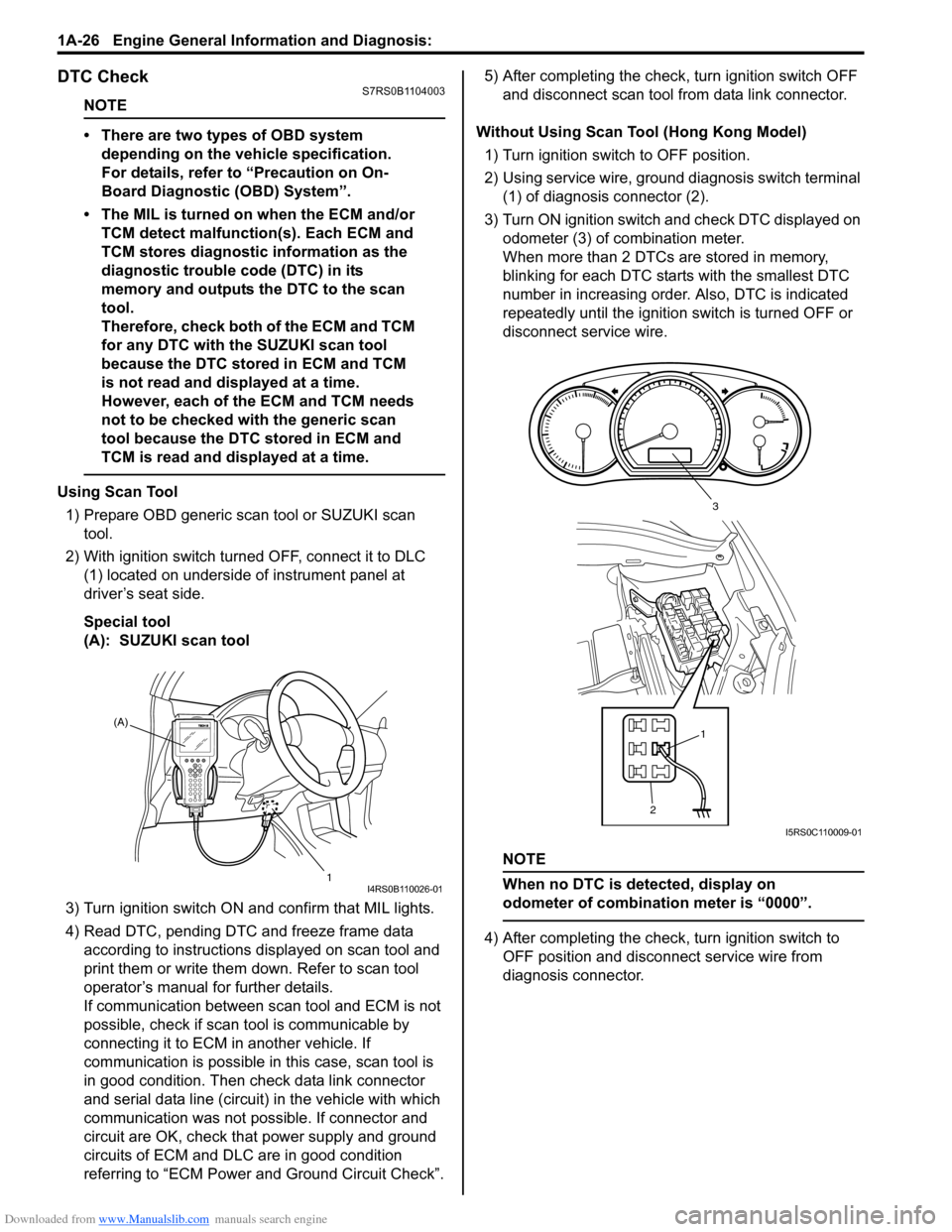
2) With ignition switch turned OFF, connect it to DLC (1) located on underside of instrument panel at
driver’s seat side.
Special tool
(A): SUZUKI scan tool
3) Turn ignition switch ON and confirm that MIL lights.
4) Read DTC, pending DTC and freeze frame data according to instructions displayed on scan tool and
print them or write them down. Refer to scan tool
operator’s manual for further details.
If communication between scan tool and ECM is not
possible, check if scan tool is communicable by
connecting it to ECM in another vehicle. If
communication is possible in this case, scan tool is
in good condition. Then check data link connector
and serial data line (circuit) in the vehicle with which
communication was not possible. If connector and
circuit are OK, check that power supply and ground
circuits of ECM and DLC are in good condition
referring to “ECM Power and Ground Circuit Check”. 5) After completing the check,
turn ignition switch OFF
and disconnect scan tool from data link connector.
Without Using Scan Tool (Hong Kong Model) 1) Turn ignition switch to OFF position.
2) Using service wire, ground diagnosis switch terminal (1) of diagnosis connector (2).
3) Turn ON ignition switch and check DTC displayed on
odometer (3) of combination meter.
When more than 2 DTCs are stored in memory,
blinking for each DTC star ts with the smallest DTC
number in increasing order. Also, DTC is indicated
repeatedly until the ignition switch is turned OFF or
disconnect service wire.
NOTE
When no DTC is detected, display on
odometer of combinatio n meter is “0000”.
4) After completing the check, turn ignition switch to
OFF position and disconnect service wire from
diagnosis connector.
(A)
1
I4RS0B110026-01
21
3
I5RS0C110009-01