2004 SUZUKI SWIFT description
[x] Cancel search: descriptionPage 2 of 1496
Downloaded from www.Manualslib.com manuals search engine IMPORTANT
WARNING/CAUTION/NOTE
Please read this manual and follow its instructions carefully. To emphasize special information, the words , and NOTE have special meanings. Pay specia l attention to the messages high-
lighted by these signal words.
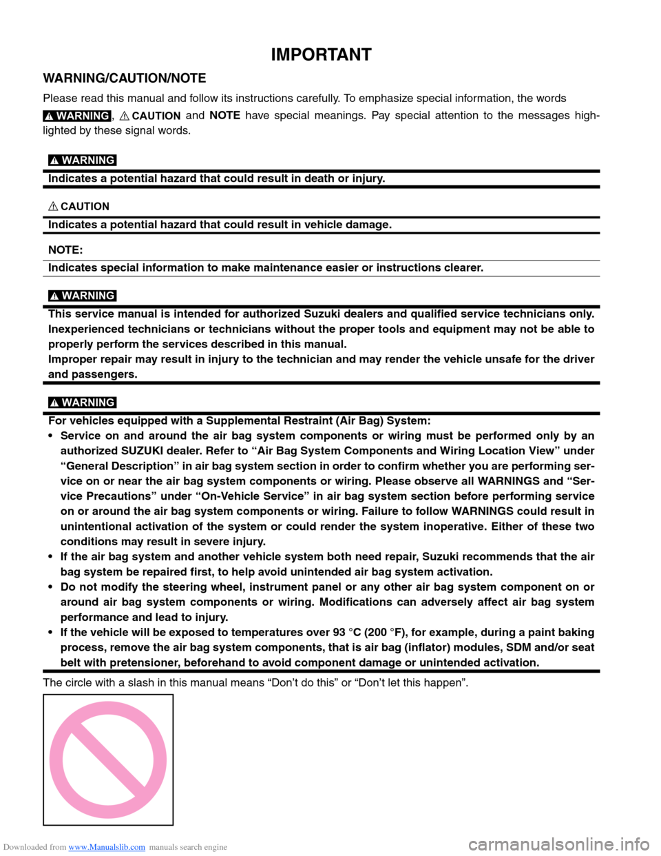
The circle with a slash in this manual me ans “Don’t do this” or “Don’t let this happen”.
WARNING!CAUTION!
Indicates a potential hazard that could result in death or injury.
WARNING!
Indicates a potential hazard that could result in vehicle damage.
CAUTION!
NOTE:
Indicates special information to make main tenance easier or instructions clearer.
This service manual is intended for authorized Su zuki dealers and qualified service technicians only.
Inexperienced technicians or technicians without the proper tools and equipment may not be able to
properly perform the services described in this manual.
Improper repair may result in injury to the technician and may render the vehicle unsafe for the driver
and passengers.
WARNING!
For vehicles equipped with a Supplemental Restraint (Air Bag) System:
• Service on and around the air bag system components or wiring must be performed only by an authorized SUZUKI dealer. Refer to “Air Bag System Components and Wiring Location View” under
“General Description” in air bag system section in order to confirm whether you are performing ser-
vice on or near the air bag system components or wiring. Please observe all WARNINGS and “Ser-
vice Precautions” under “On-Vehicl e Service” in air bag system section before performing service
on or around the air bag system components or wiring. Failure to follow WARNINGS could result in
unintentional activation of the system or could re nder the system inoperative. Either of these two
conditions may result in severe injury.
If the air bag system and another vehicle system both need repair, Suzuki recommends that the air
bag system be repaired first, to help av oid unintended air bag system activation.
Do not modify the steering wheel, instrument pa nel or any other air bag system component on or
around air bag system components or wiring. Modi fications can adversely affect air bag system
performance and lead to injury.
If the vehicle will be exposed to temperatures over 93 °C (200 °F), for example, during a paint baking
process, remove the air bag system components, th at is air bag (inflator) modules, SDM and/or seat
belt with pretensioner, beforehand to avoid component damage or unintended activation.
WARNING!
Page 3 of 1496
Downloaded from www.Manualslib.com manuals search engine FOREWORD
This manual (Volumes 1 and 2) contains procedures for diagnosis, maintenance, adjustments, minor service
operations, replacement of components (Service) and for disassembly and reassembly of major components
(Unit Repair-Overhaul).
Applicable Model:
SWIFT (RS416) produced at KOSAI plant in Japan wi th the following vehicle identification numbers
(VINs).
JSAEZC31S############
The contents are classified into sectio ns each of which is given a section number as indicated in the Table of
Contents on following page. And on the first page of ea ch individual section is an index of that section.
This manual should be kept in a handy place for ready reference of the service work.
Strict observance of the so specif ied items will enable one to obtain the full performance of the vehicle.
When replacing parts or servicing by disassembling, it is recommended to use SUZUKI genuine parts, tools and
service materials as specif ied in each description.
All information, illustrations and specif ications contained in this literature are based on the late st product infor-
mation available at the time of publication approval. And used as the main subject of description is the vehicle of
standard specificatio ns among others.
Therefore, note that illustrations may differ from the vehicle being actually serviced.
The right is reserved to make changes at any time without notice.
JSAEZC31S########
Page 21 of 1496
Downloaded from www.Manualslib.com manuals search engine Table of Contents 0- i
0
Section 0
CONTENTS
General Information
General Information ................................ 0A-1
General Description ............................................. 0A-1
Abbreviations ...................................................... 0A-1
Symbols .............................................................. 0A-2
Wire Color Symbols ............................................ 0A-2
Fasteners Information ......................................... 0A-3
Vehicle Lifting Points ........................................... 0A-5
Engine Supporting Points ................................... 0A-7
Vehicle Identification Number ............................. 0A-7
Engine Identification Number .............................. 0A-7
Transmission Identification Number .................... 0A-7
Component Locatio n ........................................... 0A-8
Warning, Caution and Information Labels Location ............................................................ 0A-8
Maintenance and Lubricat ion ................. 0B-1
Precautions........................................................... 0B-1
Precautions for Maintenance and Lubrication ..... 0B-1
Scheduled Maintenance ...................................... 0B-1 Maintenance Schedule under Normal Driving Conditions ......................................................... 0B-1
Maintenance Recommended under Severe Driving Conditions ............................................. 0B-2
Repair Instructions .............................................. 0B-3 Accessory Drive Belt Inspection.......................... 0B-3
Accessory Drive Belt Repl acement ..................... 0B-4
Valve Lash (Clearance) Inspection ..................... 0B-4
Engine Oil and Filter Change .............................. 0B-4
Engine Coolant Change ...... ................................ 0B-5
Exhaust System Inspection ................................. 0B-6
Spark Plug Replacement .................................... 0B-6
Air Cleaner Filter Inspection ................................ 0B-6
Air Cleaner Filter Replac ement ........................... 0B-6 Fuel Lines and Connections Inspection .............. 0B-6
Fuel Filter Replacement ...................................... 0B-7
Fuel Tank Inspection ........................................... 0B-7
PCV Valve Inspection ......................................... 0B-7
Fuel Evaporative Emission Control System
Inspection .......................................................... 0B-7
Brake Discs and Pads Inspection ....................... 0B-7
Brake Hoses and Pipes Inspection ..................... 0B-7
Brake Fluid Inspection......................................... 0B-8
Brake Fluid Replacement .................................... 0B-8
Brake Lever and Cable Inspection ...................... 0B-8
Clutch Fluid Inspection ........................................ 0B-8
Tires Inspection ................................................... 0B-9
Wheel Discs Inspection ....................................... 0B-9
Wheel Bearing Inspection ................................... 0B-9
Suspension System Inspection ........................... 0B-9
Steering System Inspection .............................. 0B-10
Drive Shaft (Axle) Boots Inspection .................. 0B-10
Manual Transaxle Oil Inspection ....................... 0B-10
Manual Transaxle Oil Replacement .................. 0B-10
Automatic Transaxle Fluid Level Inspection...... 0B-11
Automatic Transaxle Fluid Replacement .......... 0B-11
Automatic Transaxle Fluid Cooler Hose Inspection ........................................................ 0B-11
All Latches, Hinges and Locks Inspection......... 0B-11
HVAC Air Filter (If Equipped) Inspection ........... 0B-12
HVAC Air Filter (If Equipped) Replacement ...... 0B-12
Final Inspection for Maint enance Service ......... 0B-12
Specifications .................... .................................0B-13
Tightening Torque Specifications ...................... 0B-13
Special Tools and Equipmen t ...........................0B-13
Recommended Fluids and Lubricants............... 0B-13
Special Tool ...................................................... 0B-14
Page 22 of 1496
Downloaded from www.Manualslib.com manuals search engine 0A-1 General Information:
General Information
General Information
General Description
AbbreviationsS7RS0B0101001
A:
ABDC: After Bottom Dead Center
ABS: Anti-lock Brake System
AC: Alternating Current
A/C: Air Conditioning
A-ELR: Automatic-Emergency Locking Retractor
A/F: Air Fuel Mixture Ratio
ALR: Automatic Locking Retractor
API: American Petroleum Institute
APP sensor: Accelerator Pedal Position Sensor
A/T: Automatic Transmission , Automatic Transaxle
AT D C : After Top Dead Center
ATF: Automatic Transmission Fluid, Automatic
Transaxle Fluid
B:
B+: Battery Positive Voltage
BBDC: Before Bottom Dead Center
BCM: Body Electrical Control Module
BDC: Bottom Dead Center
BTDC: Before Top Dead Center
C:
CAN: Controller Area Network
CKT: Circuit
CKP Sensor: Crankshaft Position Sensor
CMP Sensor: Camshaft Position Sensor
CO: Carbon Monoxide
CPP Switch: Clutch Pedal Position Switch (Clutch
Switch, Clutch Start Switch)
CPU: Central Processing Unit
CRS: Child Restraint System
D:
DC: Direct Current
DLC: Data Link Connector (Assembly Line Diag. Link,
ALDL, Serial Data Link, SDL)
DOHC: Double Over Head Camshaft
DOJ: Double Offset Joint
DRL: Daytime Running Light
DTC: Diagnostic Trouble Code (Diagnostic Code)
E:
EBCM: Electronic Brake Cont rol Module, ABS Control
Module
EBD: Electronic Brake Force Distribution
ECM: Engine Control Module
ECT Sensor: Engine Coolant Temperature Sensor (Water Temp. Sensor, WTS)
EFE Heater: Early Fuel Evaporation Heater (Positive
Temperature Coefficient, PTC Heater)
EGR: Exhaust Gas Recirculation
EGRT Sensor: EGR Temperature Sensor (Recirculated
Exhaust Gas Temp. Sensor, REGTS)
ELR: Emergency Locking Retractor
ESP ®: Electronic Stability Program
EPS: Electronic Power Steering
EVAP: Evaporative Emission EVAP Canister:
Evaporative Emission Canister
(Charcoal Canister)
F:
4WD: 4 Wheel
Drive
G:
GEN: Generator
GND: Ground
GPS: Global Positioning System
H:
HVAC: Heating, Ventilating and Air Conditioning
HC: Hydrocarbons
HO2S: Heated Oxygen Sensor
I:
IAC Valve: Idle Air Control Valve (Idle Speed Control
Solenoid Valve, ISC Solenoid Valve)
IAT Sensor: Intake Air Temperature Sensor (Air
temperature Sensor, ATS)
ICM: Immobilizer Control Module
IG: Ignition
ISC Actuator: Idle Speed Control Actuator
L:
LH: Left Hand
LHD: Left Hand Drive Vehicle
LSPV: Load Sensing Proportioning Valve
M:
MAF Sensor: Mass Air Flow Sensor (Air Flow Sensor, AFS, Air Flow Meter, AFM)
MAP Sensor: Manifold Absolute Pressure Sensor
(Pressure Sensor, PS)
Max: Maximum
MFI: Multiport Fuel Injection (Mu ltipoint Fuel Injection)
Min: Minimum
MIL: Malfunction Indicator Lamp (“SERVICE ENGINE
SOON” Light)
M/T: Manual Transmission, Manual Transaxle
N:
NOx: Nitrogen Oxides
O:
OBD: On-Board Diagnostic System (Self-Diagnosis
Function)
O/D: Overdrive
OHC: Over Head Camshaft
O2S: Oxygen Sensor
P:
PCM: Powertrain Control Module
PCV: Positive Crankcase Ventilation
PNP: Park / Neutral Position
P/S: Power Steering
PSP Switch: Power Steering Pressure Switch (P/S
Pressure Switch)
R:
RH: Right Hand
RHD: Right Hand Drive Vehicle
S:
SAE: Society of Automotive Engineers
Page 25 of 1496
Downloaded from www.Manualslib.com manuals search engine General Information: 0A-4
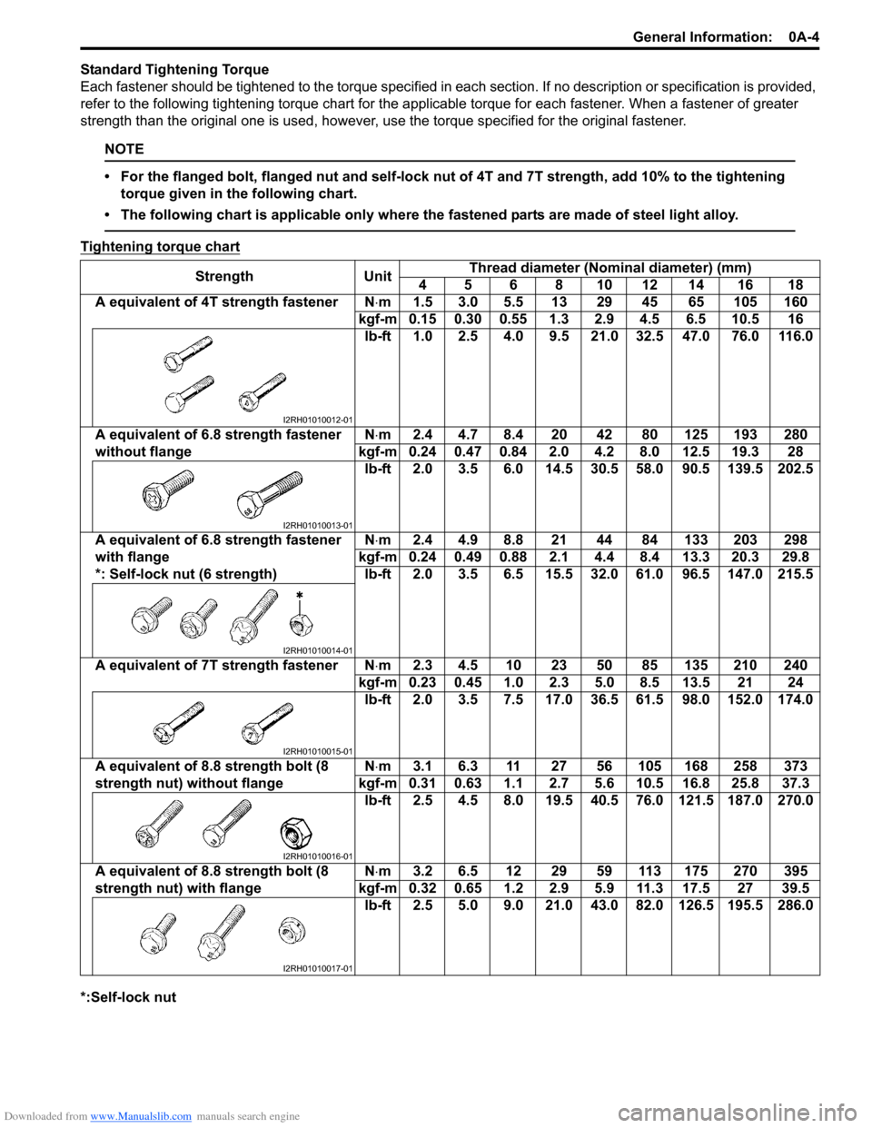
Standard Tightening Torque
Each fastener should be tightened to the torque specified in each section. If no description or specification is provided,
refer to the following tightening torque chart for the applicable torque for each fastener. When a fastener of greater
strength than the original one is used, however, use the torque specified for the original fastener.
NOTE
• For the flanged bolt, flanged nut and self-lock nut of 4T and 7T strength, add 10% to the tightening torque given in the following chart.
• The following chart is applicable only where the fastened parts are made of steel light alloy.
Tightening torque chart
*:Self-lock nut Strength Unit
Thread diameter (Nominal diameter) (mm)
4 5 6 8 10 12 14 16 18
A equivalent of 4T strength fastener N⋅ m 1.5 3.0 5.5 13 29 45 65 105 160
kgf-m 0.15 0.30 0.55 1.3 2.9 4.5 6.5 10.5 16 lb-ft 1.0 2.5 4.0 9.5 21.0 32.5 47.0 76.0 116.0
A equivalent of 6.8 strength fastener
without flange N
⋅m 2.4 4.7 8.4 20 42 80 125 193 280
kgf-m 0.24 0.47 0.84 2.0 4.2 8.0 12.5 19.3 28 lb-ft 2.0 3.5 6.0 14.5 30.5 58.0 90.5 139.5 202.5
A equivalent of 6.8 strength fastener
with flange
*: Self-lock nut (6 strength) N
⋅m 2.4 4.9 8.8 21 44 84 133 203 298
kgf-m 0.24 0.49 0.88 2.1 4.4 8.4 13.3 20.3 29.8 lb-ft 2.0 3.5 6.5 15.5 32.0 61.0 96.5 147.0 215.5
A equivalent of 7T strength fastener N⋅ m 2.3 4.5 10 23 50 85 135 210 240
kgf-m 0.23 0.45 1.0 2.3 5.0 8.5 13.5 21 24 lb-ft 2.0 3.5 7.5 17.0 36.5 61.5 98.0 152.0 174.0
A equivalent of 8.8 strength bolt (8
strength nut) without flange N
⋅m 3.1 6.3 11 27 56 105 168 258 373
kgf-m 0.31 0.63 1.1 2.7 5.6 10.5 16.8 25.8 37.3 lb-ft 2.5 4.5 8.0 19.5 40.5 76.0 121.5 187.0 270.0
A equivalent of 8.8 strength bolt (8
strength nut) with flange N
⋅m 3.2 6.5 12 29 59 113 175 270 395
kgf-m 0.32 0.65 1.2 2.9 5.9 11.3 17.5 27 39.5 lb-ft 2.5 5.0 9.0 21.0 43.0 82.0 126.5 195.5 286.0
I2RH01010012-01
I2RH01010013-01
I2RH01010014-01
I2RH01010015-01
I2RH01010016-01
I2RH01010017-01
Page 39 of 1496
Downloaded from www.Manualslib.com manuals search engine Maintenance and Lubrication: 0B-9
Tires InspectionS7RS0B0206020
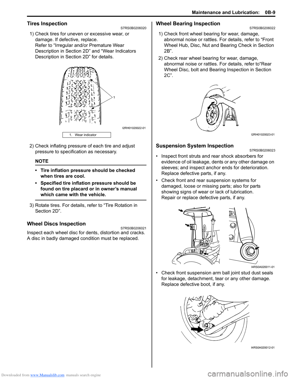
1) Check tires for uneven or excessive wear, or damage. If defective, replace.
Refer to “Irregular and/or Premature Wear
Description in Section 2D” and “Wear Indicators
Description in Section 2D” for details.
2) Check inflating pressure of each tire and adjust pressure to specification as necessary.
NOTE
• Tire inflation pressure should be checked when tires are cool.
• Specified tire inflation pressure should be found on tire placard or in owner’s manual
which came with the vehicle.
3) Rotate tires. For details, refer to “Tire Rotation in Section 2D”.
Wheel Discs InspectionS7RS0B0206021
Inspect each wheel disc for de nts, distortion and cracks.
A disc in badly damaged condition must be replaced.
Wheel Bearing InspectionS7RS0B0206022
1) Check front wheel bearing for wear, damage, abnormal noise or rattles. For details, refer to “Front
Wheel Hub, Disc, Nut and Bearing Check in Section
2B”.
2) Check rear wheel bearing for wear, damage, abnormal noise or rattles. For details, refer to“Rear
Wheel Disc, bolt and Bearing Inspection in Section
2C”.
Suspension System InspectionS7RS0B0206023
• Inspect front struts and rear shock absorbers for evidence of oil leakage, dents or any other damage on
sleeves; and inspect anchor ends for deterioration.
Replace defective parts, if any.
• Check front and rear suspension systems for damaged, loose or missing parts; also for parts
showing signs of wear or lack of lubrication.
Repair or replace defective parts, if any.
• Check front suspension arm ball joint stud dust seals for leakage, detachment, tear or any other damage.
Replace defective boot, if any.
1. Wear indicator
I2RH01020022-01
I2RH01020023-01
I4RS0A020011-01
I4RS0A020012-01
Page 45 of 1496
Downloaded from www.Manualslib.com manuals search engine Table of Contents 1- i
1
Section 1
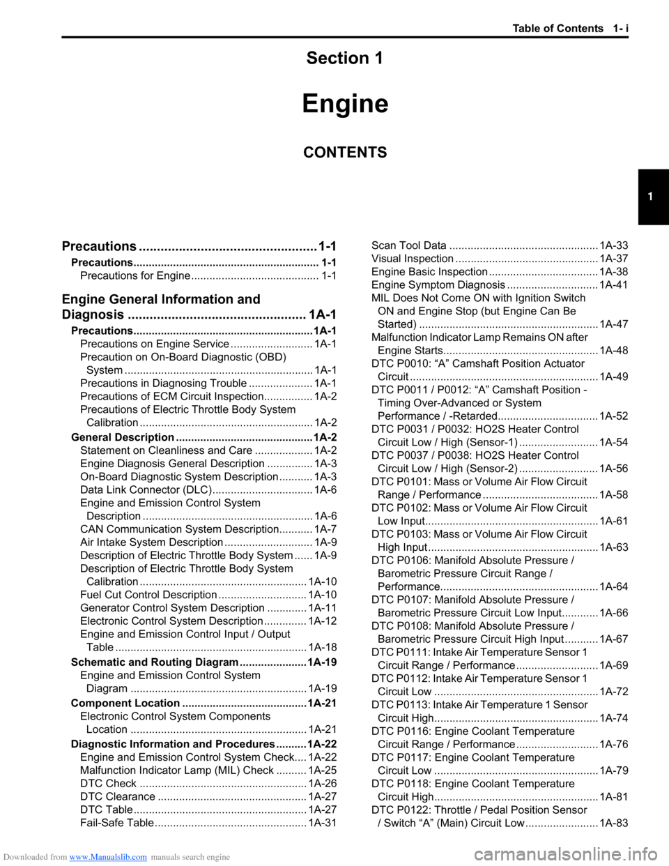
CONTENTS
Engine
Precautions ................................................. 1-1
Precautions............................................................. 1-1
Precautions for Engine .......................................... 1-1
Engine General Information and
Diagnosis ............. .................................... 1A-1
Precautions........................................................... 1A-1
Precautions on Engine Service ........................... 1A-1
Precaution on On-Board Diagnostic (OBD) System .............................................................. 1A-1
Precautions in Diagnosing Trouble ..................... 1A-1
Precautions of ECM Circuit Inspection................ 1A-2
Precautions of Electric Throttle Body System
Calibration ......................................................... 1A-2
General Description ............................................. 1A-2 Statement on Cleanliness and Care ................... 1A-2
Engine Diagnosis General Description ............... 1A-3
On-Board Diagnostic System Description ........... 1A-3
Data Link Connector (DLC) ................................. 1A-6
Engine and Emission Control System Description ........................................................ 1A-6
CAN Communication System Description........... 1A-7
Air Intake System Description ............................. 1A-9
Description of Electric Throttle Body System ...... 1A-9
Description of Electric Throttle Body System Calibration ....................................................... 1A-10
Fuel Cut Control Description ............................. 1A-10
Generator Control System Description ............. 1A-11
Electronic Control System Description .............. 1A-12
Engine and Emission Control Input / Output Table ............................................................... 1A-18
Schematic and Routing Diagram ...................... 1A-19 Engine and Emission Control System Diagram .......................................................... 1A-19
Component Locatio n ......................................... 1A-21
Electronic Control System Components Location .......................................................... 1A-21
Diagnostic Information and Procedures .......... 1A-22 Engine and Emission Control System Check.... 1A-22
Malfunction Indicator Lamp (MIL) Check .......... 1A-25
DTC Check ....................................................... 1A-26
DTC Clearance ................................................. 1A-27
DTC Table ......................................................... 1A-27
Fail-Safe Table ................ .................................. 1A-31 Scan Tool Data ................................................. 1A-33
Visual Inspection ............................................... 1A-37
Engine Basic Inspection .................................... 1A-38
Engine Symptom Diagnosis .............................. 1A-41
MIL Does Not Come ON with Ignition Switch
ON and Engine Stop (but Engine Can Be
Started) ........................................................... 1A-47
Malfunction Indicator Lamp Remains ON after Engine Starts................................................... 1A-48
DTC P0010: “A” Camshaft Position Actuator Circuit .............................................................. 1A-49
DTC P0011 / P0012: “A” Camshaft Position - Timing Over-Advanced or System
Performance / -Retarded................................. 1A-52
DTC P0031 / P0032: HO2S Heater Control Circuit Low / High (Sensor-1) .......................... 1A-54
DTC P0037 / P0038: HO2S Heater Control Circuit Low / High (Sensor-2) .......................... 1A-56
DTC P0101: Mass or Volume Air Flow Circuit Range / Performance ...................................... 1A-58
DTC P0102: Mass or Volume Air Flow Circuit Low Input......................................................... 1A-61
DTC P0103: Mass or Volume Air Flow Circuit High Input ........................................................ 1A-63
DTC P0106: Manifold Absolute Pressure /
Barometric Pressure Circuit Range /
Performance.................................................... 1A-64
DTC P0107: Manifold Absolute Pressure /
Barometric Pressure Circ uit Low Input............ 1A-66
DTC P0108: Manifold Absolute Pressure /
Barometric Pressure Circ uit High Input ........... 1A-67
DTC P0111: Intake Air Temperature Sensor 1 Circuit Range / Performance ........................... 1A-69
DTC P0112: Intake Air Temperature Sensor 1 Circuit Low ...................................................... 1A-72
DTC P0113: Intake Air Temperature 1 Sensor Circuit High...................................................... 1A-74
DTC P0116: Engine Coolant Temperature Circuit Range / Performance ........................... 1A-76
DTC P0117: Engine Coolant Temperature Circuit Low ...................................................... 1A-79
DTC P0118: Engine Coolant Temperature Circuit High...................................................... 1A-81
DTC P0122: Throttle / Pedal Position Sensor / Switch “A” (Main) Circuit Low ........................ 1A-83
Page 47 of 1496
Downloaded from www.Manualslib.com manuals search engine Table of Contents 1-iii
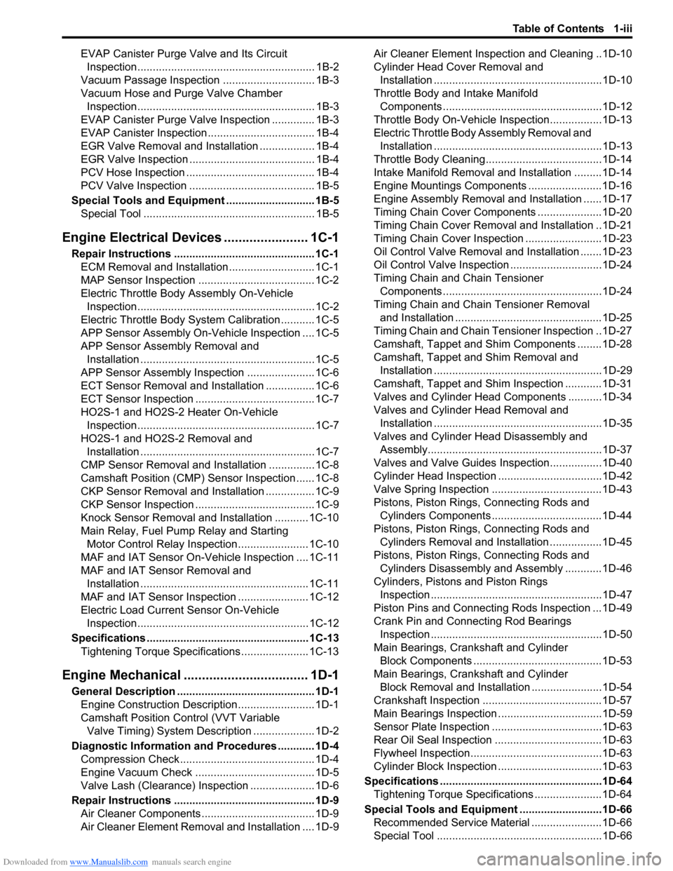
EVAP Canister Purge Valve and Its Circuit
Inspection.......................................................... 1B-2
Vacuum Passage Inspection .............................. 1B-3
Vacuum Hose and Purge Valve Chamber Inspection.......................................................... 1B-3
EVAP Canister Purge Valve Inspection .............. 1B-3
EVAP Canister Inspection ... ................................ 1B-4
EGR Valve Removal and Installation .................. 1B-4
EGR Valve Inspection ......................................... 1B-4
PCV Hose Inspection .......................................... 1B-4
PCV Valve Inspection ......................................... 1B-5
Special Tools and Equipmen t ............................. 1B-5
Special Tool ........................................................ 1B-5
Engine Electrical Devices .. ..................... 1C-1
Repair Instructions .............................................. 1C-1
ECM Removal and Installation ............................ 1C-1
MAP Sensor Inspection ...................................... 1C-2
Electric Throttle Body Assembly On-Vehicle
Inspection.......................................................... 1C-2
Electric Throttle Body System Calibration ........... 1C-5
APP Sensor Assembly On-V ehicle Inspection .... 1C-5
APP Sensor Assembly Removal and Installation ......................................................... 1C-5
APP Sensor Assembly Inspection ...................... 1C-6
ECT Sensor Removal and In stallation ................ 1C-6
ECT Sensor Inspection ....................................... 1C-7
HO2S-1 and HO2S-2 Heater On-Vehicle Inspection.......................................................... 1C-7
HO2S-1 and HO2S-2 Removal and Installation ......................................................... 1C-7
CMP Sensor Removal and In stallation ............... 1C-8
Camshaft Position (CMP) Se nsor Inspection ...... 1C-8
CKP Sensor Removal and Installation ................ 1C-9
CKP Sensor Inspection ....................................... 1C-9
Knock Sensor Removal and Installation ........... 1C-10
Main Relay, Fuel Pump Relay and Starting
Motor Control Relay Inspection....................... 1C-10
MAF and IAT Sensor On-Vehicle Inspection .... 1C-11
MAF and IAT Sensor Removal and Installation ....................................................... 1C-11
MAF and IAT Sensor Inspection ....................... 1C-12
Electric Load Current Sensor On-Vehicle Inspection........................................................ 1C-12
Specifications ..................................................... 1C-13
Tightening Torque Specifications ...................... 1C-13
Engine Mechanical ......... ......................... 1D-1
General Description ............................................. 1D-1
Engine Construction Description ......................... 1D-1
Camshaft Position Control (VVT Variable Valve Timing) System Description .................... 1D-2
Diagnostic Information and Procedures ............ 1D-4 Compression Check ............................................ 1D-4
Engine Vacuum Check ....................................... 1D-5
Valve Lash (Clearance) Inspection ..................... 1D-6
Repair Instructions .............................................. 1D-9 Air Cleaner Components ..................................... 1D-9
Air Cleaner Element Removal and Installation .... 1D-9 Air Cleaner Element Ins
pection and Cleaning ..1D-10
Cylinder Head Co ver Removal and
Installation .......................................................1D-10
Throttle Body and Intake Manifold
Components ....................................................1D-12
Throttle Body On-Vehicle Inspection.................1D-13
Electric Throttle Body Assembly Removal and Installation .......................................................1D-13
Throttle Body Cleaning......................................1D-14
Intake Manifold Removal and Installation .........1D-14
Engine Mountings Components ........................1D-16
Engine Assembly Removal and Installation ......1D-17
Timing Chain Cover Components .....................1D-20
Timing Chain Cover Removal and Installation ..1D-21
Timing Chain Cover Inspection .........................1D-23
Oil Control Valve Removal and Installation .......1D-23
Oil Control Valve Inspection ..............................1D-24
Timing Chain and Chain Tensioner Components ....................................................1D-24
Timing Chain and Chain Tensioner Removal and Installation ................................................1D-25
Timing Chain and Chain Tensioner Inspection ..1D-27
Camshaft, Tappet and Shim Components ........1D-28
Camshaft, Tappet and Shim Removal and Installation .......................................................1D-29
Camshaft, Tappet and Shim Inspection ............1D-31
Valves and Cylinder Head Components ...........1D-34
Valves and Cylinder Head Removal and
Installation .......................................................1D-35
Valves and Cylinder Head Disassembly and Assembly.........................................................1D-37
Valves and Valve Guides Inspection.................1D-40
Cylinder Head Inspection . .................................1D-42
Valve Spring Inspection ....................................1D-43
Pistons, Piston Rings , Connecting Rods and
Cylinders Components ....................................1D-44
Pistons, Piston Rings , Connecting Rods and
Cylinders Removal and Installation .................1D-45
Pistons, Piston Rings , Connecting Rods and
Cylinders Disassembly and Assembly ............1D-46
Cylinders, Pistons and Piston Rings Inspection ........................................................1D-47
Piston Pins and Connecting Rods Inspection ...1D-49
Crank Pin and Connecting Rod Bearings Inspection ........................................................1D-50
Main Bearings, Cran kshaft and Cylinder
Block Components ..........................................1D-53
Main Bearings, Cran kshaft and Cylinder
Block Removal and Installa tion .......................1D-54
Crankshaft Inspection .......................................1D-57
Main Bearings Inspection . .................................1D-59
Sensor Plate Inspection ....................................1D-63
Rear Oil Seal Inspection ...................................1D-63
Flywheel Inspection...........................................1D-63
Cylinder Block Inspection ..................................1D-63
Specifications .................... .................................1D-64
Tightening Torque Specifications ......................1D-64
Special Tools and Equipmen t ...........................1D-66
Recommended Service Material .......................1D-66
Special Tool ......................................................1D-66