2004 SUZUKI SWIFT wiring body
[x] Cancel search: wiring bodyPage 1005 of 1496
Downloaded from www.Manualslib.com manuals search engine Air Conditioning System: Automatic Type 7B-57
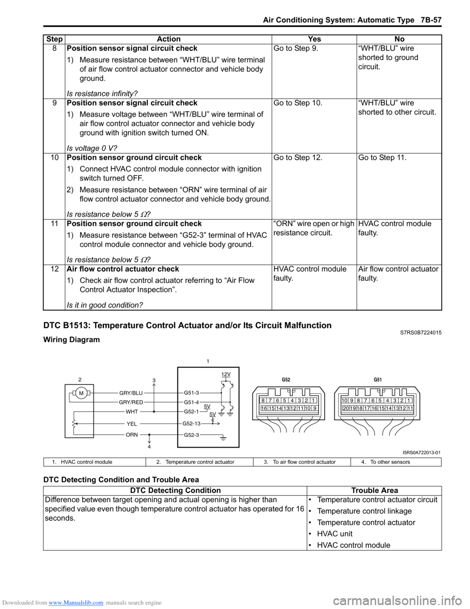
DTC B1513: Temperature Control Actuator and/or Its Circuit MalfunctionS7RS0B7224015
Wiring Diagram
DTC Detecting Condition and Trouble Area8
Position sensor signal circuit check
1) Measure resistance between “WHT/BLU” wire terminal
of air flow control actuator connector and vehicle body
ground.
Is resistance infinity? Go to Step 9. “WHT/BLU” wire
shorted to ground
circuit.
9 Position sensor signal circuit check
1) Measure voltage between “WHT/BLU” wire terminal of
air flow control actuator connector and vehicle body
ground with ignition switch turned ON.
Is voltage 0 V? Go to Step 10. “WHT/BLU” wire
shorted to other circuit.
10 Position sensor ground circuit check
1) Connect HVAC control module connector with ignition
switch turned OFF.
2) Measure resistance between “ORN” wire terminal of air flow control actuator connector and vehicle body ground.
Is resistance below 5
Ω? Go to Step 12. Go to Step 11.
11 Position sensor ground circuit check
1) Measure resistance between “G52-3” terminal of HVAC
control module connector and vehicle body ground.
Is resistance below 5
Ω? “ORN” wire open or high
resistance circuit.
HVAC control module
faulty.
12 Air flow control actuator check
1) Check air flow control actuator referring to “Air Flow
Control Actuator Inspection”.
Is it in good condition? HVAC control module
faulty.
Air flow control actuator
faulty.
Step Action Yes No
7812910
65 431516 14 13 12 11
G52
789101920121112
65 431718 16 15 14 13
G51
M 12V
5V 5V
YEL
WHT
GRY/BLU
GRY/RED
2
1
ORN
G51-3
G51-4
G52-1
G52-13
G52-3
3
4
I5RS0A722013-01
1. HVAC control module 2. Temperature control actuator 3. To air flow control actuator 4. To other sensors
DTC Detecting Condition Trouble Area
Difference between target opening an d actual opening is higher than
specified value even though temperature control actuator has operated for 16
seconds. • Temperature control actuator circuit
• Temperature control linkage
• Temperature control actuator
• HVAC unit
• HVAC control module
Page 1008 of 1496
Downloaded from www.Manualslib.com manuals search engine 7B-60 Air Conditioning System: Automatic Type
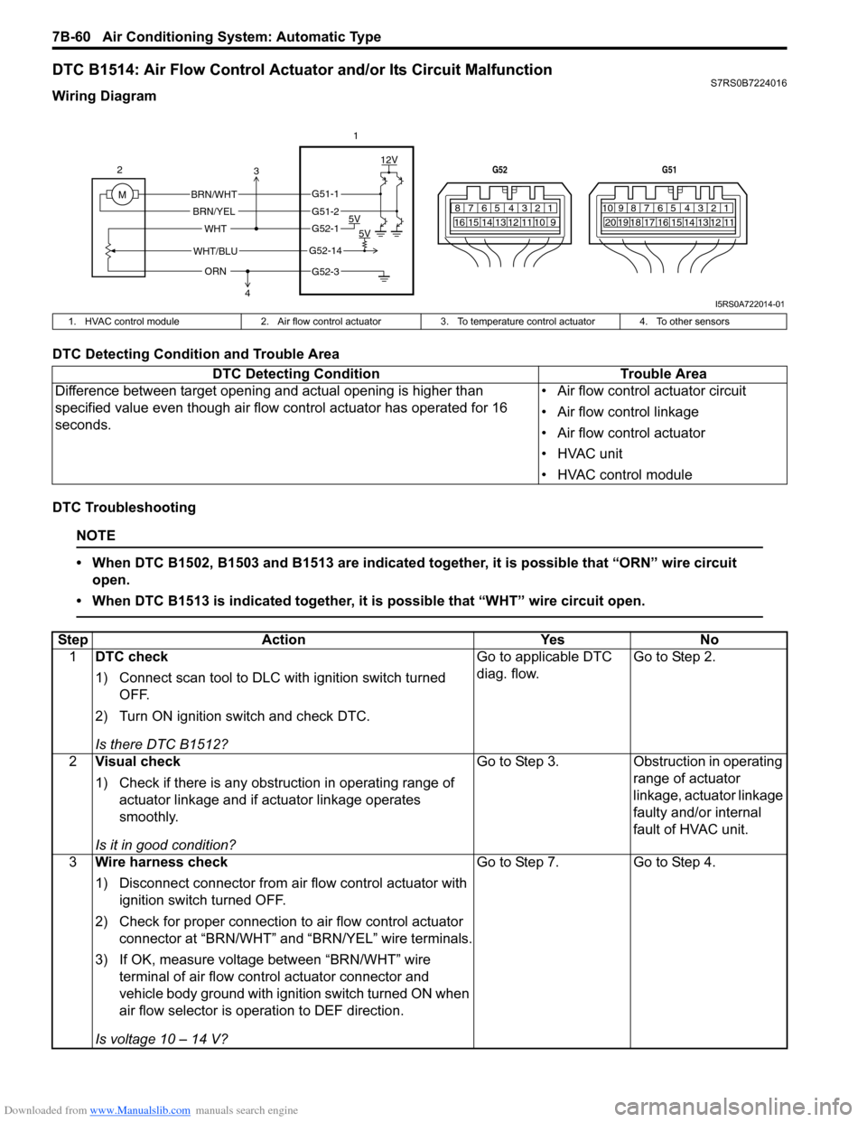
DTC B1514: Air Flow Control Actuator and/or Its Circuit MalfunctionS7RS0B7224016
Wiring Diagram
DTC Detecting Condition and Trouble Area
DTC Troubleshooting
NOTE
• When DTC B1502, B1503 and B1513 are indicated together, it is possible that “ORN” wire circuit open.
• When DTC B1513 is indicated together, it is possible that “WHT” wire circuit open.
7812910
65 431516 14 13 12 11
G52
789101920121112
65 431718 16 15 14 13
G51
M 12V
5V 5V
WHT/BLU
WHT
BRN/WHT
BRN/YEL
2
1
ORN
G51-1
G51-2
G52-1
G52-14
G52-3
3
4
I5RS0A722014-01
1. HVAC control module 2. Air flow control actuator3. To temperature control actuator 4. To other sensors
DTC Detecting Condition Trouble Area
Difference between target opening and actual opening is higher than
specified value even though air flow control actuator has operated for 16
seconds. • Air flow control actuator circuit
• Air flow control linkage
• Air flow control actuator
• HVAC unit
• HVAC control module
Step
Action YesNo
1 DTC check
1) Connect scan tool to DLC with ignition switch turned
OFF.
2) Turn ON ignition switch and check DTC.
Is there DTC B1512? Go to applicable DTC
diag. flow.
Go to Step 2.
2 Visual check
1) Check if there is any obstruction in operating range of
actuator linkage and if actuator linkage operates
smoothly.
Is it in good condition? Go to Step 3.
Obstruction in operating
range of actuator
linkage, actuator linkage
faulty and/or internal
fault of HVAC unit.
3 Wire harness check
1) Disconnect connector from air flow control actuator with
ignition switch turned OFF.
2) Check for proper connection to air flow control actuator
connector at “BRN/WHT” and “BRN/YEL” wire terminals.
3) If OK, measure voltage between “BRN/WHT” wire terminal of air flow control actuator connector and
vehicle body ground with ignition switch turned ON when
air flow selector is operation to DEF direction.
Is voltage 10 – 14 V? Go to Step 7.
Go to Step 4.
Page 1010 of 1496
Downloaded from www.Manualslib.com manuals search engine 7B-62 Air Conditioning System: Automatic Type
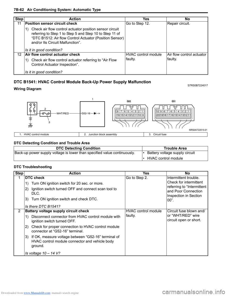
DTC B1541: HVAC Control Module Back-Up Power Supply MalfunctionS7RS0B7224017
Wiring Diagram
DTC Detecting Condition and Trouble Area
DTC Troubleshooting11
Position sensor circuit check
1) Check air flow control actuator position sensor circuit
referring to Step 1 to Step 5 and Step 10 to Step 11 of
“DTC B1512: Air flow Control Actuator (Position Sensor)
and/or Its Circuit Malfunction”.
Is it in good condition? Go to Step 12. Repair circuit.
12 Air flow control actuator check
1) Check air flow control actuator referring to “Air Flow
Control Actuator Inspection”.
Is it in good condition? HVAC control module
faulty.
Air flow control actuator
faulty.
Step Action Yes No
WHT/RED
2 17812910
65 431516 14 13 12 11
G52
789101920121112
65 431718 16 15 14 13
G51
3
G52-16
I5RS0A722015-01
1. HVAC control module
2. Junction block assembly 3. Circuit fuse
DTC Detecting Condition Trouble Area
Back-up power supply voltage is lo wer than specified value continuously. • Battery voltage supply circuit
• HVAC control module
StepAction YesNo
1 DTC check
1) Turn ON ignition switch for 20 sec. or more.
2) Ignition switch turned OF F and connect scan tool to
DLC.
3) Turn ON ignition switch and check DTC.
Is there DTC B1541? Go to Step 2.
Intermittent trouble.
Check for intermittent
referring to “Intermittent
and Poor Connection
Inspection in Section
00”.
2 Battery voltage supply circuit check
1) Disconnect connector from HVAC control module with
ignition switch turned OFF.
2) Check for proper connection to HVAC control module connector at “G52-16” terminal.
3) If OK, measure voltage between “G52-16” terminal of HVAC control module connector and vehicle body
ground.
Is voltage 10 – 14 V? HVAC control module
faulty.
Circuit fuse blown and/
or “WHT/RED” wire
circuit open or short.
Page 1091 of 1496
Downloaded from www.Manualslib.com manuals search engine Air Bag System: 8B-53
NOTE
Upon completion of inspection and repair work, perform the following items.
• Reconnect all air bag system components and ensure all components are properly mounted.
• Clear DTCs referring to “DTC Clearance”, if any.
• Repeat “Air Bag Diagnostic System Check” to confirm that the trouble has been corrected.
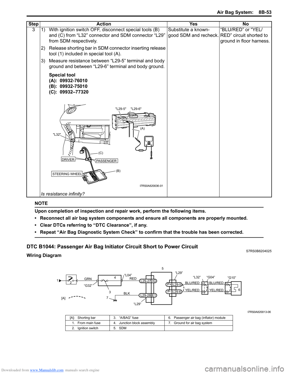
DTC B1044: Passenger Air Bag Initiator Circuit Short to Power CircuitS7RS0B8204025
Wiring Diagram3 1) With ignition switch OFF, disconnect special tools (B)
and (C) from “L32” connector and SDM connector “L29”
from SDM respectively.
2) Release shorting bar in SDM connector inserting release tool (1) included in special tool (A).
3) Measure resistance between “L29-5” terminal and body ground and between “L29-6” terminal and body ground.
Special tool
(A): 09932-76010
(B): 09932-75010
(C): 09932–77320
Is resistance infinity? Substitute a known-
good SDM and recheck.
“BLU/RED” or “YEL/
RED” circuit shorted to
ground in floor harness.
Step Action Yes No
(B)
(C)
"L32"
STEERING WHEEL
DRIVERPASSENGER
(A)
"L29-6"
"L29-5"
I7RS0A820036-01
1
2
3
GRN
RED
7
BLK
L29-27
L29-28 IG
E1
4
“L29”
“L04”
“G32”
“L29”
L29-5
P+
L29-6
P-YEL/RED
BLU/RED
YEL/RED
BLU/RED
56
“L32” “G04”
“G10”
[A]
I7RS0A820013-06
[A]: Shorting bar
3. “A/BAG” fuse 6. Passenger air bag (inflator) module
1. From main fuse 4. Junction block assembly 7. Ground for air bag system
2. Ignition switch 5. SDM
Page 1094 of 1496
Downloaded from www.Manualslib.com manuals search engine 8B-56 Air Bag System:
NOTE
Upon completion of inspection and repair work, perform the following items.
• Reconnect all air bag system components and ensure all components are properly mounted.
• Clear DTCs referring to “DTC Clearance”, if any.
• Repeat “Air Bag Diagnostic System Check” to confirm that the trouble has been corrected.
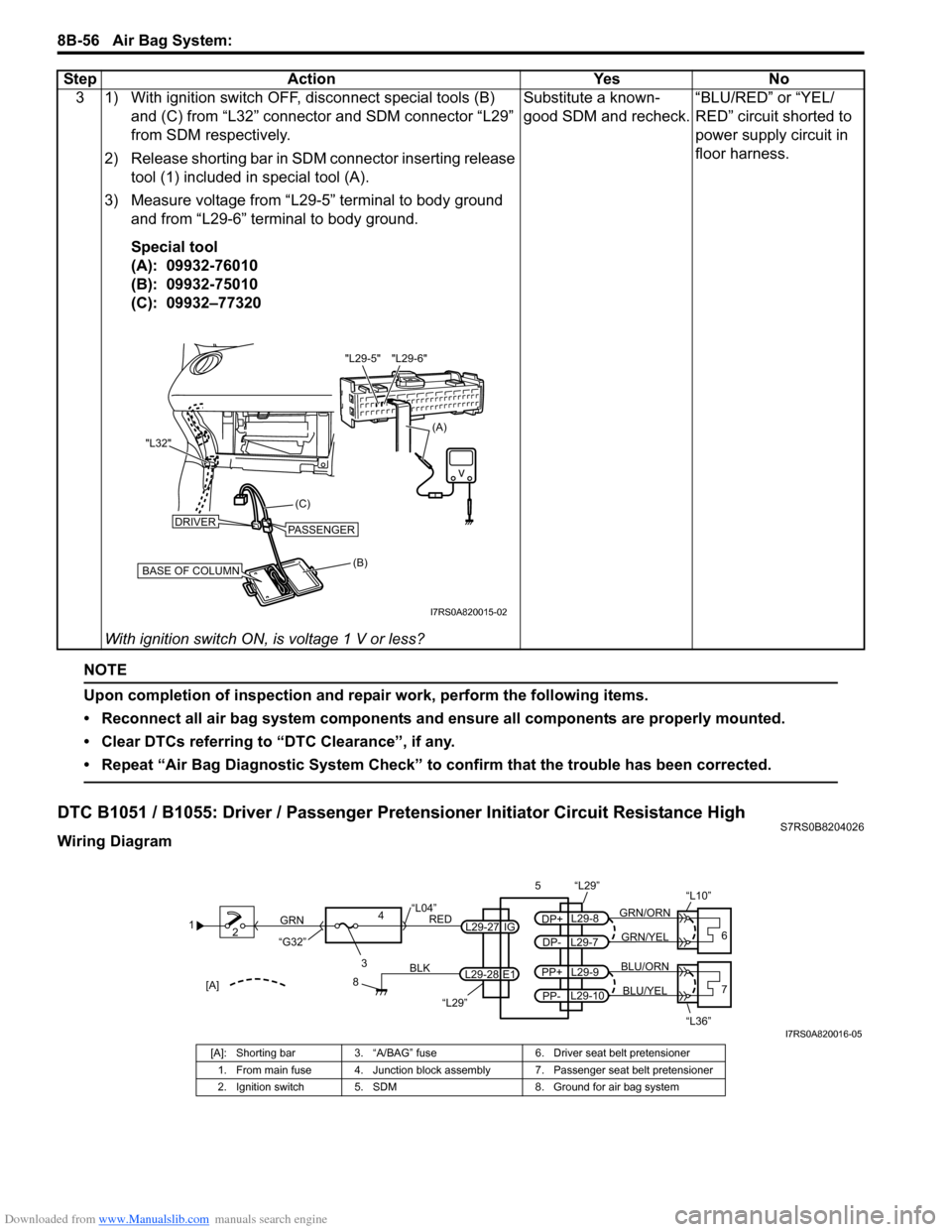
DTC B1051 / B1055: Driver / Passenger Pretensioner Initiator Circuit Resistance HighS7RS0B8204026
Wiring Diagram3 1) With ignition switch OFF, disconnect special tools (B)
and (C) from “L32” connector and SDM connector “L29”
from SDM respectively.
2) Release shorting bar in SDM connector inserting release tool (1) included in special tool (A).
3) Measure voltage from “L29-5” terminal to body ground and from “L29-6” terminal to body ground.
Special tool
(A): 09932-76010
(B): 09932-75010
(C): 09932–77320
With ignition switch ON, is voltage 1 V or less? Substitute a known-
good SDM and recheck.
“BLU/RED” or “YEL/
RED” circuit shorted to
power supply circuit in
floor harness.
Step Action Yes No
(B)
(C)
"L32"
BASE OF COLUMN
DRIVERPASSENGER
(A)
"L29-6"
"L29-5"
I7RS0A820015-02
1
2
3
GRN
RED
8
BLK
L29-27
L29-28 IG
E1
4
“L29”
“L04”
“G32”
“L29”
L29-8
DP+
L29-7
DP-GRN/YEL
GRN/ORN
56
“L10”
L29-9
PP+
L29-10
PP-BLU/YEL
BLU/ORN7
“L36”[A]
I7RS0A820016-05
[A]: Shorting bar 3. “A/BAG” fuse 6. Driver seat belt pretensioner
1. From main fuse 4. Junction block assembly 7. Passenger seat belt pretensioner
2. Ignition switch 5. SDM 8. Ground for air bag system
Page 1100 of 1496
Downloaded from www.Manualslib.com manuals search engine 8B-62 Air Bag System:
NOTE
Upon completion of inspection and repair work, perform the following items.
• Reconnect all air bag system components and ensure all components are properly mounted.
• Clear DTCs referring to “DTC Clearance”, if any.
• Repeat “Air Bag Diagnostic System Check” to confirm that the trouble has been corrected.
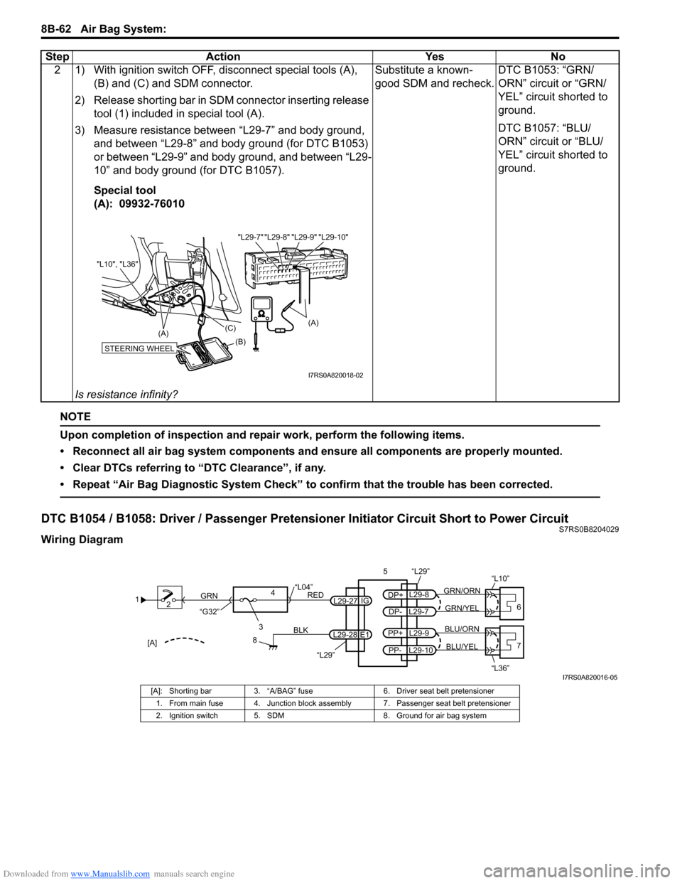
DTC B1054 / B1058: Driver / Passenger Pretensioner Initiator Circuit Short to Power CircuitS7RS0B8204029
Wiring Diagram2 1) With ignition switch OFF, disconnect special tools (A),
(B) and (C) and SDM connector.
2) Release shorting bar in SDM connector inserting release tool (1) included in special tool (A).
3) Measure resistance between “L29-7” and body ground, and between “L29-8” and body ground (for DTC B1053)
or between “L29-9” and body ground, and between “L29-
10” and body ground (for DTC B1057).
Special tool
(A): 09932-76010
Is resistance infinity? Substitute a known-
good SDM and recheck.
DTC B1053: “GRN/
ORN” circuit or “GRN/
YEL” circuit shorted to
ground.
DTC B1057: “BLU/
ORN” circuit or “BLU/
YEL” circuit shorted to
ground.
Step Action Yes No
"L29-8" "L29-9" "L29-10"
"L29-7"
(A)
STEERING WHEEL(B)
(C)
(A)
"L10", "L36"
I7RS0A820018-02
1
2
3
GRN
RED
8
BLK
L29-27
L29-28 IG
E1
4
“L29”
“L04”
“G32”
“L29”
L29-8
DP+
L29-7
DP-GRN/YEL
GRN/ORN
56
“L10”
L29-9
PP+
L29-10
PP-BLU/YEL
BLU/ORN7
“L36”[A]
I7RS0A820016-05
[A]: Shorting bar 3. “A/BAG” fuse 6. Driver seat belt pretensioner
1. From main fuse 4. Junction block assembly 7. Passenger seat belt pretensioner
2. Ignition switch 5. SDM 8. Ground for air bag system
Page 1102 of 1496
Downloaded from www.Manualslib.com manuals search engine 8B-64 Air Bag System:
NOTE
Upon completion of inspection and repair work, perform the following items.
• Reconnect all air bag system components and ensure all components are properly mounted.
• Clear DTCs referring to “DTC Clearance”, if any.
• Repeat “Air Bag Diagnostic System Check” to confirm that the trouble has been corrected.
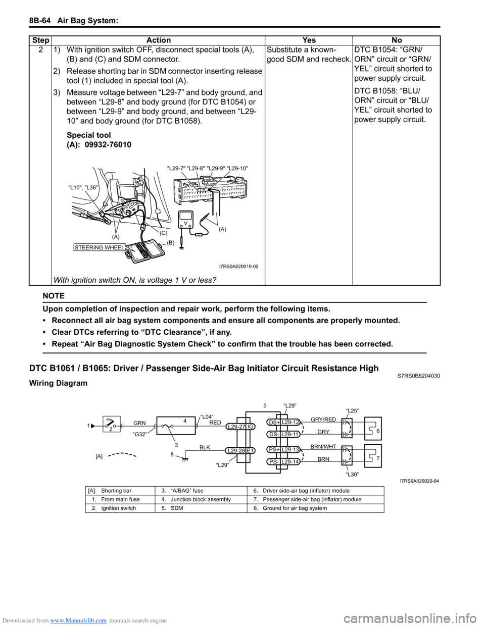
DTC B1061 / B1065: Driver / Passenger Side-Air Bag Initiator Circuit Resistance HighS7RS0B8204030
Wiring Diagram2 1) With ignition switch OFF, disconnect special tools (A),
(B) and (C) and SDM connector.
2) Release shorting bar in SDM connector inserting release tool (1) included in special tool (A).
3) Measure voltage between “L29-7” and body ground, and between “L29-8” and body ground (for DTC B1054) or
between “L29-9” and body ground, and between “L29-
10” and body ground (for DTC B1058).
Special tool
(A): 09932-76010
With ignition switch ON, is voltage 1 V or less? Substitute a known-
good SDM and recheck.
DTC B1054: “GRN/
ORN” circuit or “GRN/
YEL” circuit shorted to
power supply circuit.
DTC B1058: “BLU/
ORN” circuit or “BLU/
YEL” circuit shorted to
power supply circuit.
Step Action Yes No
"L29-8" "L29-9" "L29-10"
"L29-7"
(A)
STEERING WHEEL(B)
(C)
(A)
"L10", "L36"
I7RS0A820019-02
1
2
3
GRN
RED
8
BLK
L29-27
L29-28 IG
E1
4
“L29”
“L04”
“G32”
“L29”
L29-12
DS+
L29-11
DS-GRY
GRY/RED
56
“L25”
L29-13
PS+
L29-14
PS-BRN
BRN/WHT7
“L30”[A]
I7RS0A820020-04
[A]: Shorting bar 3. “A/BAG” fuse 6. Driver side-air bag (inflator) module
1. From main fuse 4. Junction block assembly 7. Passenger side-air bag (inflator) module
2. Ignition switch 5. SDM 8. Ground for air bag system
Page 1119 of 1496
Downloaded from www.Manualslib.com manuals search engine Air Bag System: 8B-81
DTC Troubleshooting
NOTE
Upon completion of inspection and repair work, perform the following items.
• Reconnect all air bag system components and ensure all components are properly mounted.
• Clear DTCs referring to “DTC Clearance”, if any.
• Repeat “Air Bag Diagnostic System Check” to confirm that the trouble has been corrected.
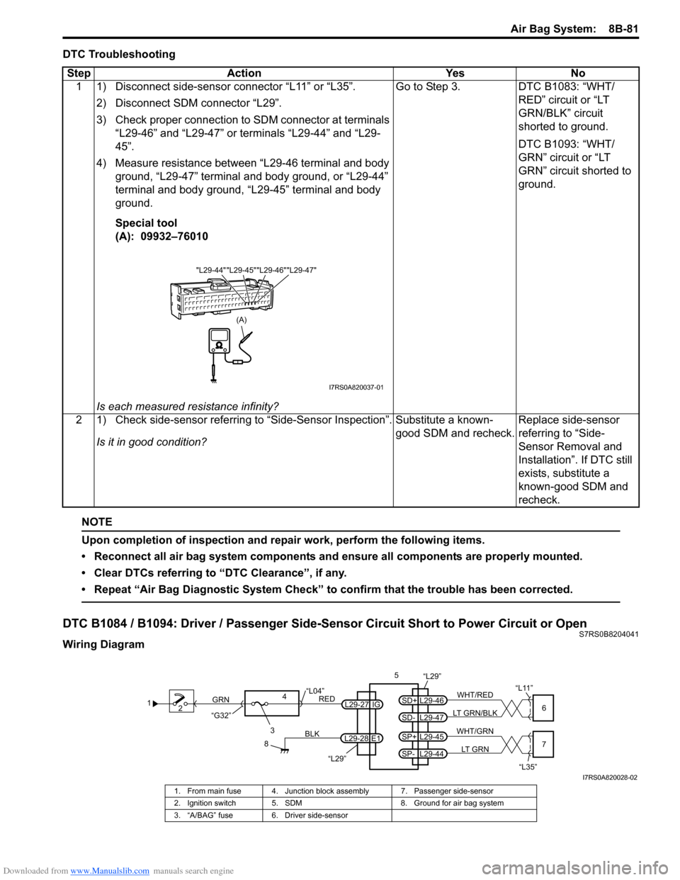
DTC B1084 / B1094: Driver / Passenger Side-Sensor Circuit Short to Power Circuit or OpenS7RS0B8204041
Wiring DiagramStep Action Yes No
1 1) Disconnect side-sensor connector “L11” or “L35”.
2) Disconnect SDM connector “L29”.
3) Check proper connection to SDM connector at terminals “L29-46” and “L29-47” or terminals “L29-44” and “L29-
45”.
4) Measure resistance between “L29-46 terminal and body ground, “L29-47” terminal and body ground, or “L29-44”
terminal and body ground, “L29-45” terminal and body
ground.
Special tool
(A): 09932–76010
Is each measured resistance infinity? Go to Step 3. DTC B1083: “WHT/
RED” circuit or “LT
GRN/BLK” circuit
shorted to ground.
DTC B1093: “WHT/
GRN” circuit or “LT
GRN” circuit shorted to
ground.
2 1) Check side-sensor referring to “Side-Sensor Inspection”. Is it in good condition? Substitute a known-
good SDM and recheck.
Replace side-sensor
referring to “Side-
Sensor Removal and
Installation”. If DTC still
exists, substitute a
known-good SDM and
recheck.
"L29-45""L29-46""L29-47"
"L29-44"
(A)
I7RS0A820037-01
12
3
GRN
RED
8
BLK
L29-27
L29-28 IG
E1
4
“L29”
“L04”
“G32”
“L29”5
WHT/RED
LT GRN/BLKL29-46
SD+
L29-47
SD-6
“L11”
WHT/GRN
LT GRNL29-45
SP+
L29-44
SP-7
“L35”
I7RS0A820028-02
1. From main fuse 4. Junction blo ck assembly 7. Passenger side-sensor
2. Ignition switch 5. SDM 8. Ground for air bag system
3. “A/BAG” fuse 6. Driver side-sensor