2004 SUZUKI SWIFT cooling
[x] Cancel search: coolingPage 278 of 1496
Downloaded from www.Manualslib.com manuals search engine 1C-6 Engine Electrical Devices:
APP Sensor Assembly InspectionS7RS0B1306007
Check APP sensor (main and sub) output voltage as
following steps.
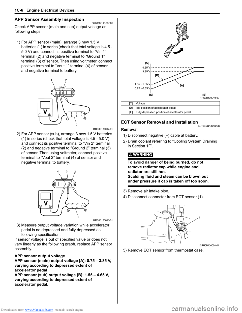
1) For APP sensor (main) , arrange 3 new 1.5 V
batteries (1) in series (check that total voltage is 4.5 -
5.0 V) and connect its positive terminal to “Vin 1”
terminal (2) and negative terminal to “Ground 1”
terminal (3) of sensor. Then using voltmeter, connect
positive terminal to “Vout 1” terminal (4) of sensor
and negative terminal to battery.
2) For APP sensor (s ub), arrange 3 new 1.5 V batteries
(1) in series (check that total voltage is 4.5 - 5.0 V)
and connect its positive terminal to “Vin 2” terminal
(2) and negative terminal to “Ground 2” terminal (3)
of sensor. Then using volt meter, connect positive
terminal to “Vout 2” terminal (4) of sensor and
negative termin al to battery.
3) Measure output voltage variation while accelerator pedal is no depressed and fully depressed as
following specification.
If sensor voltage is out of specified value or does not
vary linearly as the followin g graph, replace APP sensor
assembly.
APP sensor output voltage
APP sensor (main) output voltage [A]: 0.75 – 3.85 V,
varying according to depressed extent of
accelerator pedal
APP sensor (sub) output voltage [B]: 1.55 – 4.65 V,
varying according to depressed extent of
accelerator pedal.
ECT Sensor Removal and InstallationS7RS0B1306008
Removal
1) Disconnect negative (–) cable at battery.
2) Drain coolant referring to “Cooling System Draining in Section 1F”.
WARNING!
To avoid danger of being burned, do not
remove radiator cap while engine and
radiator are still hot.
Scalding fluid and steam can be blown out
under pressure if cap is taken off too soon.
3) Remove air intake pipe.
4) Disconnect connector from ECT sensor (1).
5) Remove ECT sensor from thermostat case.
1
234I4RS0B130012-01
1
234I4RS0B130013-01
[C]: Voltage
[D]: Idle position of accelerator pedal
[E]: Fully depressed position of accelerator pedal
[C]
[B]
[D] [E] [A]
4.65 V
3.85 V
1.55 - 1.65 V
0.75 - 0.85 V
I4RS0B130010-02
1
I2RH0B130008-01
Page 279 of 1496
Downloaded from www.Manualslib.com manuals search engine Engine Electrical Devices: 1C-7
Installation
Reverse removal procedure noting the following.
• Clean mating surfaces of ECT sensor and thermostat case.
• Check O-ring for damage and replace, if necessary.
• Tighten ECT sensor (1) to specified torque.
Tightening torque
ECT sensor (a): 15 N·m (1.5 kgf-m, 11.0 lb-ft)
• Connect connector to ECT sensor securely.
• Refill coolant referring to “Cooling System Flush and
Refill in Section 1F”.
ECT Sensor InspectionS7RS0B1306009
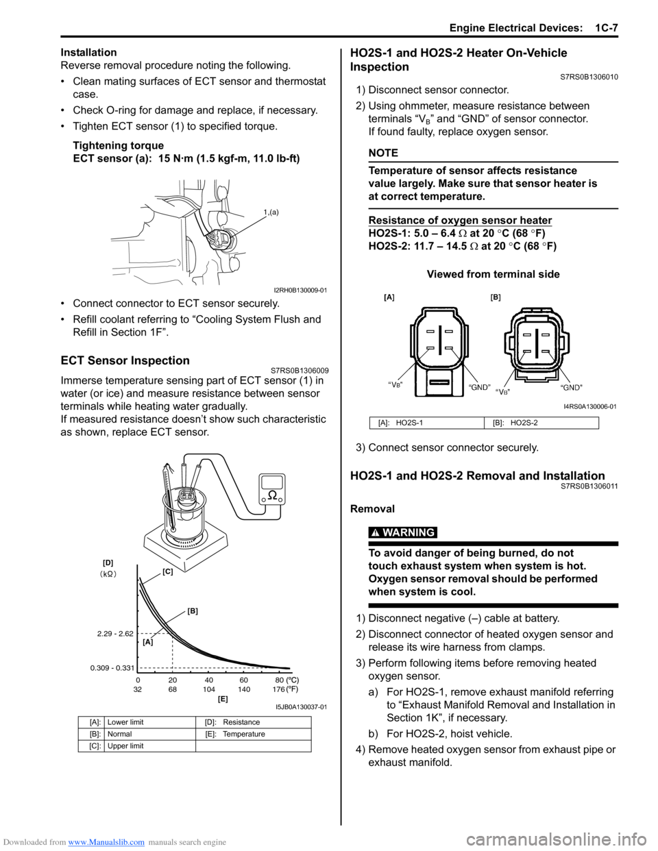
Immerse temperature sensing part of ECT sensor (1) in
water (or ice) and measure resistance between sensor
terminals while heating water gradually.
If measured resistance doesn’t show such characteristic
as shown, replace ECT sensor.
HO2S-1 and HO2S-2 Heater On-Vehicle
Inspection
S7RS0B1306010
1) Disconnect sensor connector.
2) Using ohmmeter, measure resistance between terminals “V
B” and “GND” of sensor connector.
If found faulty, replace oxygen sensor.
NOTE
Temperature of sensor affects resistance
value largely. Make sure that sensor heater is
at correct temperature.
Resistance of oxygen sensor heater
HO2S-1: 5.0 – 6.4 Ω at 20 °C (68 °F)
HO2S-2: 11.7 – 14.5 Ω at 20 °C (68 °F)
Viewed from terminal side
3) Connect sensor co nnector securely.
HO2S-1 and HO2S-2 Removal and InstallationS7RS0B1306011
Removal
WARNING!
To avoid danger of being burned, do not
touch exhaust system when system is hot.
Oxygen sensor removal should be performed
when system is cool.
1) Disconnect negative (–) cable at battery.
2) Disconnect connector of heated oxygen sensor and
release its wire harness from clamps.
3) Perform following items before removing heated oxygen sensor.
a) For HO2S-1, remove exhaust manifold referring to “Exhaust Manifold Remo val and Installation in
Section 1K”, if necessary.
b) For HO2S-2, hoist vehicle.
4) Remove heated oxygen sensor from exhaust pipe or exhaust manifold.
[A]: Lower limit [D]: Resistance
[B]: Normal [E]: Temperature
[C]: Upper limit
1,(a)
I2RH0B130009-01
20
0
68
32 104 140 176 40 60 80
[E]
2.29 - 2.62
0.309 - 0.331
[A]
[B]
[C][D]
I5JB0A130037-01
[A]: HO2S-1 [B]: HO2S-2
I4RS0A130006-01
Page 298 of 1496

Downloaded from www.Manualslib.com manuals search engine 1D-13 Engine Mechanical:
Throttle Body On-Vehicle InspectionS7RS0B1406006
Check electric throttle body assembly referring to
“Throttle Valve Operation Check” and “Electric Throttle
Body Assembly Operation Check” under “Electric
Throttle Body Assembly On-Vehicle Inspection in
Section 1C”.
Electric Throttle Body Assembly Removal and
Installation
S7RS0B1406007
CAUTION!
Never disassemble electric throttle body.
Disassembly will spoil its original
performance. If faulty condition is found,
replace it with new one.
NOTE
After replacing electric throttle body
assembly, perform calibration of throttle
valve referring to “Electric Throttle Body
System Calibration in Section 1C”.
Removal
1) Disconnect negative cable at battery.
2) Drain coolant referring to “Cooling System Draining in Section 1F”.
3) Remove air cleaner assembly referring to “Air Cleaner Components”.
4) Detach EVAP canister and purge valve chamber, and remove air cleaner outlet hose.
5) Disconnect engine coolant hoses (1) and breather hose (2) from electric throttle body assembly (3).
6) Disconnect connector (4) from electric throttle body assembly.
7) Remove electric throttle body assembly from intake
manifold. Installation
1) Clean mating surfaces and install new throttle body gasket (1) to intake manifold.
2) Install electric throttle bo dy assembly (1) to intake
manifold.
3) Connect connector (2) to electric throttle body assembly securely.
4) Connect engine coolant hoses (3) and breather hose (4) to electric thrott le body assembly (1).
5) Install air cleaner assembly referring to “Air Cleaner
Components”.
6) Install EVAP canister and purge valve chamber and air cleaner outlet hose.
7) Refill coolant referring to “Cooling System Flush and
Refill in Section 1F”.
8) Connect negative cable at battery.
2
4
3
1I4RS0B140004-02
1
I6RS0C140013-02
4
2
1
3I4RS0B140006-01
Page 300 of 1496
Downloaded from www.Manualslib.com manuals search engine 1D-15 Engine Mechanical:
Installation
Reverse removal procedure for installation noting the
followings.
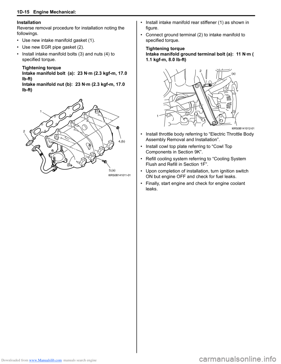
• Use new intake manifold gasket (1).
• Use new EGR pipe gasket (2).
• Install intake manifold bolts (3) and nuts (4) to specified torque.
Tightening torque
Intake manifold bolt (a): 23 N·m (2.3 kgf-m, 17.0
lb-ft)
Intake manifold nut (b): 23 N·m (2.3 kgf-m, 17.0
lb-ft) • Install intake manifold rear stiffener (1) as shown in
figure.
• Connect ground terminal (2) to intake manifold to specified torque.
Tightening torque
Intake manifold ground terminal bolt (a): 11 N·m (
1.1 kgf-m, 8.0 lb-ft)
• Install throttle body referrin g to “Electric Throttle Body
Assembly Removal and Installation”.
• Install cowl top plate referring to “Cowl Top Components in Section 9K”.
• Refill cooling system refe rring to “Cooling System
Flush and Refill in Section 1F”.
• Upon completion of installation, turn ignition switch ON but engine OFF and check for fuel leaks.
• Finally, start engine and check for engine coolant leaks.
1
2
3,(a)
4,(b)
I6RS0B141011-01
(a)
12
I6RS0B141012-01
Page 305 of 1496

Downloaded from www.Manualslib.com manuals search engine Engine Mechanical: 1D-20
15) Install A/C compressor to its bracket (if equipped) referring to “Compressor Assembly Removal and
Installation in Section 7B” or “Compressor Assembly
Removal and Installa tion in Section 7B”.
16) Adjust A/C compressor belt tension (if equipped) referring to “Compressor Drive Belt Inspection and
Adjustment in Section 7B” or “Compressor Drive Belt
Inspection and Adjustment in Section 7B”.
17) Check to ensure that a ll removed parts are back in
place.
Reinstall any necessary parts which have not been
reinstalled.
18) Refill cooling system with coolant referring to “Cooling System Flush and Refill in Section 1F”. 19) Refill engine with engine oil
referring to “Engine Oil
and Filter Change in Section 0B”.
20) Refill transaxle with transa xle oil referring to“Manual
Transaxle Oil Change in Section 5B” or “A/T Fluid
Change in Section 5A”.
21) Install battery and tray.
22) Connect positive and negative cable at battery.
23) Install engine hood and connect windshield washer hose.
24) Verify that there is no fu el leakage, coolant leakage,
oil leakage and exhaust gas leakage at each
connection.
Timing Chain Cover ComponentsS7RS0B1406012
I6RS0C140015-02
1. Crankshaft pulley bolt 13. Oil gallery pipe No.2 bolt
2. Crankshaft pulley 14. Oil gallery pipe No.3
3. Oil seal : Apply engine oil to oil seal lip. 15. Oil gallery pipe No.3 bolt
4. Timing chain cover : Apply sealant 99000-31140 to the mating surface of cylinder and cylinder head.
: Apply sealant 99000-31260 to the mating surface of timing chain cover referring to the
figure of Step 4) of “Installation” under “Timing Chain Cover Removal and Installation”. 16. O-ring
: Apply engine oil.
5. Pin 17. Oil control valve
6. Cap bolt 18. Oil control valve mounting nut
7. Timing chain cover mounting bolts 19. Cap
8. Timing chain cover mounting nut : 11 N ⋅m (1.1 kgf-m, 8.0 lb-ft)
9. Oil gallery pipe No.1 :25 N⋅m (2.5 kgf-m, 18.0 lb-ft)
Page 338 of 1496
Downloaded from www.Manualslib.com manuals search engine 1D-53 Engine Mechanical:
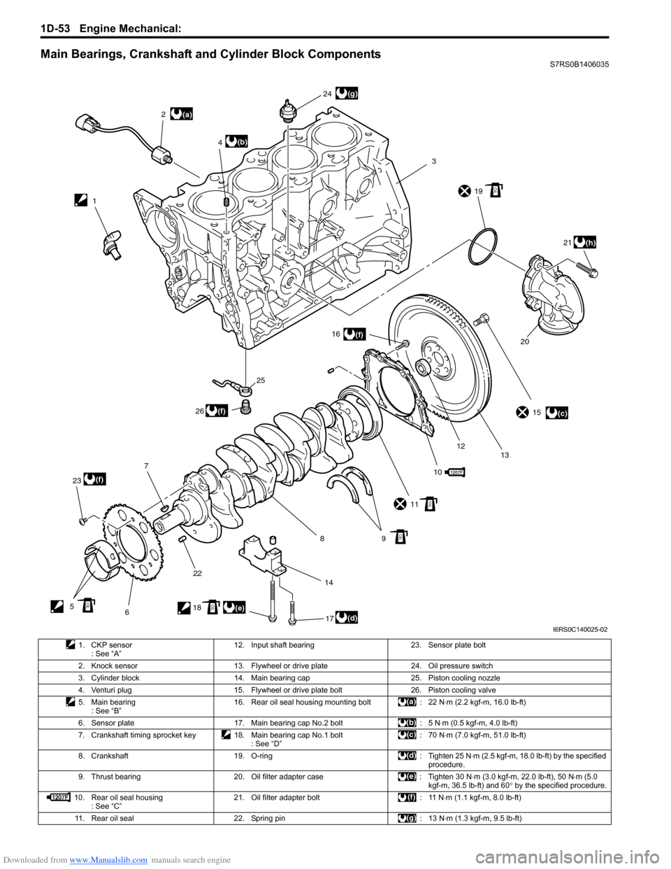
Main Bearings, Crankshaft and Cylinder Block ComponentsS7RS0B1406035
(a)
(c)
(d)(e)
(b)
(f)
(f)
(f)
(g)
(h)
12
3
4
5 67
8910
11 15
12 13
14 16
17
18 19
2021
22
23 24
25
26
OIL
OIL
OIL
OILOIL
I6RS0C140025-02
1. CKP sensor : See “A” 12. Input shaft bearing 23. Sensor plate bolt
2. Knock sensor 13. Flywheel or drive plate 24. Oil pressure switch 3. Cylinder block 14. Main bearing cap 25. Piston cooling nozzle
4. Venturi plug 15. Flywheel or drive plate bolt 26. Piston cooling valve
5. Main bearing : See “B” 16. Rear oil seal housing mounting bolt : 22 N
⋅m (2.2 kgf-m, 16.0 lb-ft)
6. Sensor plate 17. Main bearing cap No.2 bolt : 5 N ⋅m (0.5 kgf-m, 4.0 lb-ft)
7. Crankshaft timing sprocket key 18. Main bearing cap No.1 bolt : See “D”:70 N
⋅m (7.0 kgf-m, 51.0 lb-ft)
8. Crankshaft 19. O-ring : Tighten 25 N ⋅m (2.5 kgf-m, 18.0 lb-ft) by the specified
procedure.
9. Thrust bearing 20. Oil filter adapter case : Tighten 30 N ⋅m (3.0 kgf-m, 22.0 lb-ft), 50 N⋅m (5.0
kgf-m, 36.5 lb-ft) and 60 ° by the specified procedure.
10. Rear oil seal housing : See “C” 21. Oil filter adapter bolt : 11 N
⋅m (1.1 kgf-m, 8.0 lb-ft)
11. Rear oil seal 22. Spring pin : 13 N ⋅m (1.3 kgf-m, 9.5 lb-ft)
Page 339 of 1496
Downloaded from www.Manualslib.com manuals search engine Engine Mechanical: 1D-54
Main Bearings, Crankshaft and Cylinder Block
Removal and Installation
S7RS0B1406036
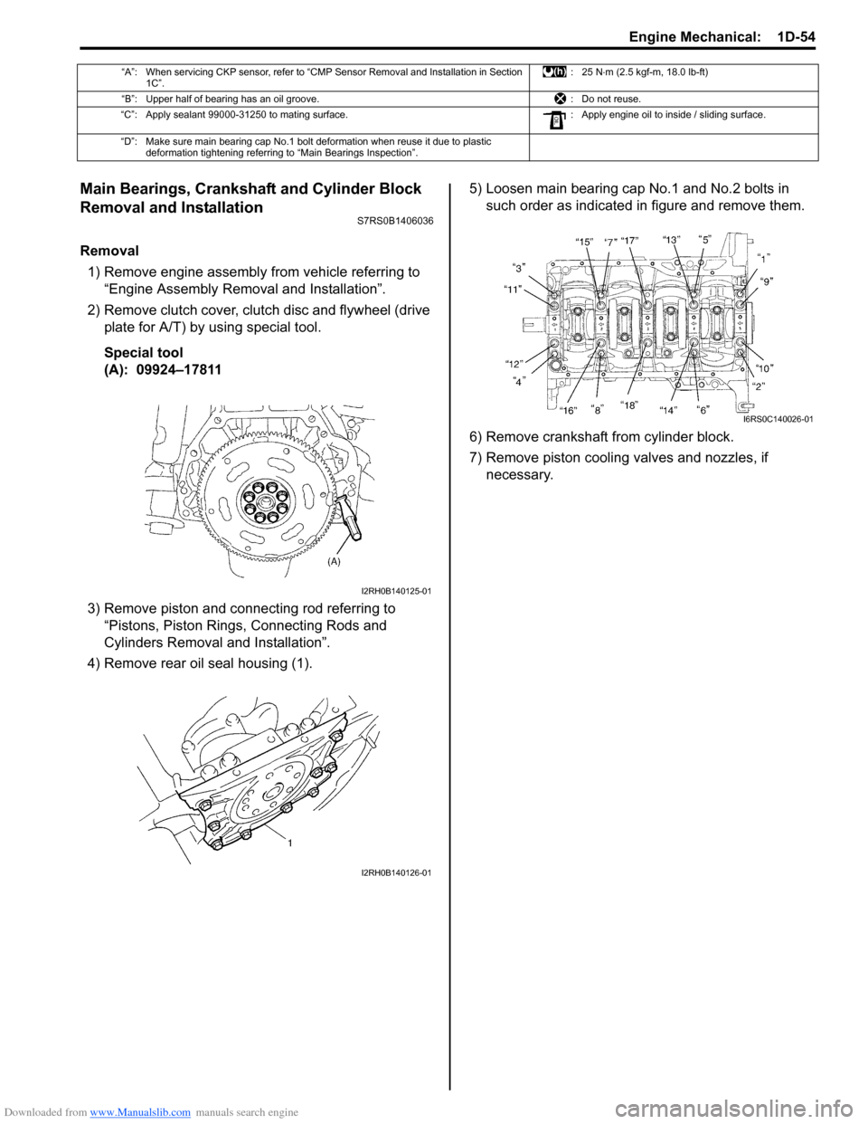
Removal1) Remove engine assembly from vehicle referring to “Engine Assembly Removal and Installation”.
2) Remove clutch cover, clut ch disc and flywheel (drive
plate for A/T) by using special tool.
Special tool
(A): 09924–17811
3) Remove piston and connecting rod referring to “Pistons, Piston Rings, Connecting Rods and
Cylinders Removal and Installation”.
4) Remove rear oil seal housing (1). 5) Loosen main bearing cap No.1 and No.2 bolts in
such order as indicated in figure and remove them.
6) Remove crankshaft from cylinder block.
7) Remove piston cooling valves and nozzles, if necessary.
“A”: When servicing CKP sensor, refer to “CMP Sensor Removal and Installation in Section 1C”. :25 N
⋅m (2.5 kgf-m, 18.0 lb-ft)
“B”: Upper half of bearing has an oil groove. : Do not reuse.
“C”: Apply sealant 99000-31250 to mating surface. : Apply engine oil to inside / sliding surface.
“D”: Make sure main bearing cap No.1 bolt deformation when reuse it due to plastic deformation tightening referring to “Main Bearings Inspection”.
I2RH0B140125-01
I2RH0B140126-01
I6RS0C140026-01
Page 340 of 1496
Downloaded from www.Manualslib.com manuals search engine 1D-55 Engine Mechanical:
Installation
NOTE
• Use new bearing cap No.1 bolts. They are deformed once they are used because they
are plastic deformation tightening bolts.
• All parts to be insta lled must be perfectly
clean.
• Be sure to oil crankshaft journals, journal bearings, thrust bearings, crankpins,
connecting rod bearings, pistons, piston
rings and cylinder bores.
• Journal bearings, bearing caps, connecting rods, rod bearings, rod bearing
caps, pistons and piston rings are in
combination sets. Do not disturb such
combination and make sure that each part
goes back to where it came from, when
installing.
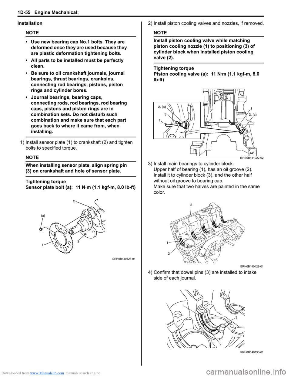
1) Install sensor plate (1) to crankshaft (2) and tighten bolts to spec ified torque.
NOTE
When installing sensor plate, align spring pin
(3) on crankshaft and hole of sensor plate.
Tightening torque
Sensor plate bolt (a): 11 N·m (1.1 kgf-m, 8.0 lb-ft) 2) Install piston cooling valves and nozzles, if removed.
NOTE
Install piston cooling valve while matching
piston cooling nozzle (1) to positioning (3) of
cylinder block when installed piston cooling
valve (2).
Tightening torque
Piston cooling valve (a): 11 N·m (1.1 kgf-m, 8.0
lb-ft)
3) Install main bearings to cylinder block. Upper half of bearing (1), has an oil groove (2).
Install it to cylinder block (3), and the other half
without oil groove to bearing cap.
Make sure that two halves are painted in the same
color.
4) Confirm that dowel pins (3 ) are installed to intake
side of each journal.
I2RH0B140128-01
I6RS0B141022-02
I2RH0B140129-01
I2RH0B140130-01