2004 SUZUKI SWIFT start
[x] Cancel search: startPage 1428 of 1496
Downloaded from www.Manualslib.com manuals search engine 10B-25 Body Electrical Control System:
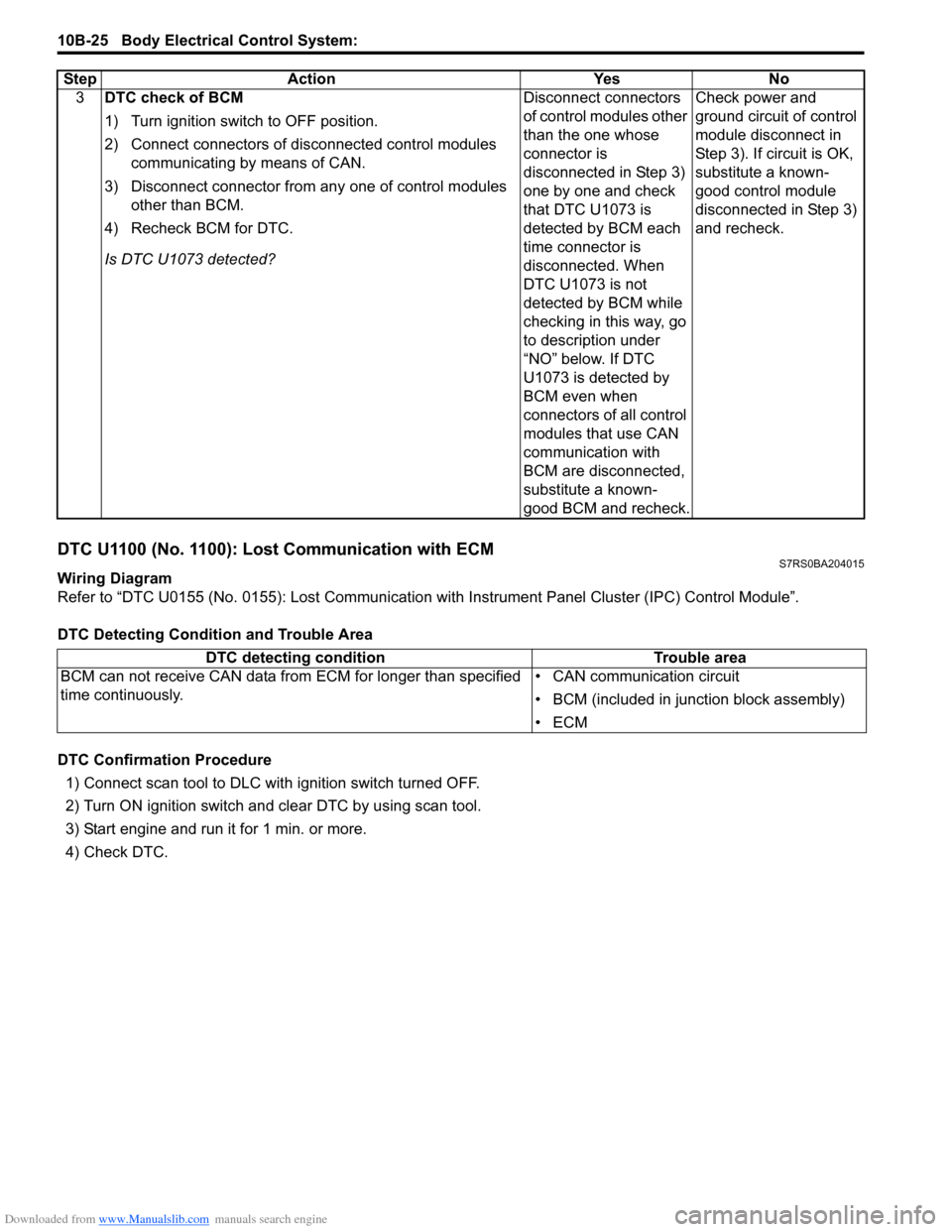
DTC U1100 (No. 1100): Lost Communication with ECMS7RS0BA204015
Wiring Diagram
Refer to “DTC U0155 (No. 0155): Lost Communication with Instrument Panel Cluster (IPC) Control Module”.
DTC Detecting Condition and Trouble Area
DTC Confirmation Procedure 1) Connect scan tool to DLC with ignition switch turned OFF.
2) Turn ON ignition switch and clear DTC by using scan tool.
3) Start engine and run it for 1 min. or more.
4) Check DTC. 3
DTC check of BCM
1) Turn ignition switch to OFF position.
2) Connect connectors of disconnected control modules
communicating by means of CAN.
3) Disconnect connector from any one of control modules other than BCM.
4) Recheck BCM for DTC.
Is DTC U1073 detected? Disconnect connectors
of control modules other
than the one whose
connector is
disconnected in Step 3)
one by one and check
that DTC U1073 is
detected by BCM each
time connector is
disconnected. When
DTC U1073 is not
detected by BCM while
checking in this way, go
to description under
“NO” below. If DTC
U1073 is detected by
BCM even when
connectors of all control
modules that use CAN
communication with
BCM are disconnected,
substitute a known-
good BCM and recheck.Check power and
ground circuit of control
module disconnect in
Step 3). If circuit is OK,
substitute a known-
good control module
disconnected in Step 3)
and recheck.
Step Action Yes No
DTC detecting condition
Trouble area
BCM can not receive CAN data from ECM for longer than specified
time continuously. • CAN communication circuit
• BCM (included in junction block assembly)
•ECM
Page 1430 of 1496
Downloaded from www.Manualslib.com manuals search engine 10B-27 Body Electrical Control System:
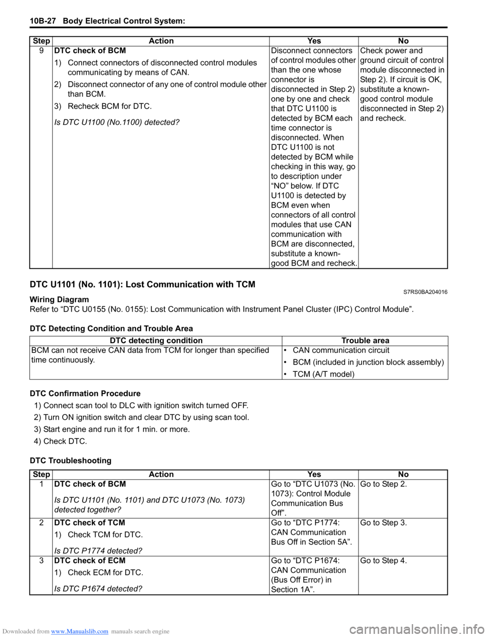
DTC U1101 (No. 1101): Lost Communication with TCMS7RS0BA204016
Wiring Diagram
Refer to “DTC U0155 (No. 0155): Lost Communication with Instrument Panel Cluster (IPC) Control Module”.
DTC Detecting Condition and Trouble Area
DTC Confirmation Procedure 1) Connect scan tool to DLC with ignition switch turned OFF.
2) Turn ON ignition switch and clear DTC by using scan tool.
3) Start engine and run it for 1 min. or more.
4) Check DTC.
DTC Troubleshooting 9
DTC check of BCM
1) Connect connectors of disconnected control modules
communicating by means of CAN.
2) Disconnect connector of any one of control module other than BCM.
3) Recheck BCM for DTC.
Is DTC U1100 (No.1100) detected? Disconnect connectors
of control modules other
than the one whose
connector is
disconnected in Step 2)
one by one and check
that DTC U1100 is
detected by BCM each
time connector is
disconnected. When
DTC U1100 is not
detected by BCM while
checking in this way, go
to description under
“NO” below. If DTC
U1100 is detected by
BCM even when
connectors of all control
modules that use CAN
communication with
BCM are disconnected,
substitute a known-
good BCM and recheck.Check power and
ground circuit of control
module disconnected in
Step 2). If circuit is OK,
substitute a known-
good control module
disconnected in Step 2)
and recheck.
Step Action Yes No
DTC detecting condition
Trouble area
BCM can not receive CAN data from TCM for longer than specified
time continuously. • CAN communication circuit
• BCM (included in junction block assembly)
• TCM (A/T model)
Step
Action YesNo
1 DTC check of BCM
Is DTC U1101 (No. 1101) and DTC U1073 (No. 1073)
detected together? Go to “DTC U1073 (No.
1073): Control Module
Communication Bus
Off”.Go to Step 2.
2 DTC check of TCM
1) Check TCM for DTC.
Is DTC P1774 detected? Go to “DTC P1774:
CAN Communication
Bus Off in Section 5A”.
Go to Step 3.
3 DTC check of ECM
1) Check ECM for DTC.
Is DTC P1674 detected? Go to “DTC P1674:
CAN Communication
(Bus Off Error) in
Section 1A”.Go to Step 4.
Page 1432 of 1496
Downloaded from www.Manualslib.com manuals search engine 10B-29 Body Electrical Control System:
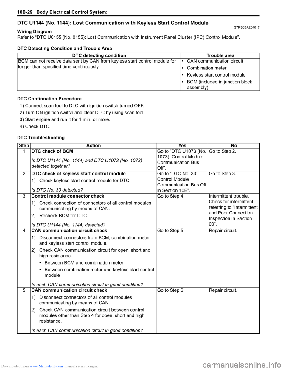
DTC U1144 (No. 1144): Lost Communication with Keyless Start Control ModuleS7RS0BA204017
Wiring Diagram
Refer to “DTC U0155 (No. 0155): Lost Communication with Instrument Panel Cluster (IPC) Control Module”.
DTC Detecting Condition and Trouble Area
DTC Confirmation Procedure 1) Connect scan tool to DLC with ignition switch turned OFF.
2) Turn ON ignition switch and clear DTC by using scan tool.
3) Start engine and run it for 1 min. or more.
4) Check DTC.
DTC Troubleshooting DTC detecting condition Trouble area
BCM can not receive data sent by CAN from keyless start control module for
longer than specified time continuously. • CAN communication circuit
• Combination meter
• Keyless start control module
• BCM (included in junction block
assembly)
Step Action YesNo
1 DTC check of BCM
Is DTC U1144 (No. 1144) and DTC U1073 (No. 1073)
detected together? Go to “DTC U1073 (No.
1073): Control Module
Communication Bus
Off”.Go to Step 2.
2 DTC check of keyless start control module
1) Check keyless start co ntrol module for DTC.
Is DTC No. 33 detected? Go to “DTC No. 33:
Control Module
Communication Bus Off
in Section 10E”.Go to Step 3.
3 Control module connector check
1) Check connection of connectors of all control modules
communicating by means of CAN.
2) Recheck BCM for DTC.
Is DTC U1144 (No. 1144) detected? Go to Step 4.
Intermittent trouble.
Check for intermittent
referring to “Intermittent
and Poor Connection
Inspection in Section
00”.
4 CAN communication circuit check
1) Disconnect connectors from BCM, combination meter
and keyless start control module.
2) Check CAN communication circuit for open, short and high resistance.
• Between BCM and combination meter
• Between combination meter and keyless start control module
Is each CAN communication circuit in good condition? Go to Step 5.
Repair circuit.
5 CAN communication circuit check
1) Disconnect connectors of all control modules
communicating by means of CAN.
2) Check CAN communication circuit between control modules other than Step 4 for open, short and high
resistance.
Is each CAN communication circuit in good condition? Go to Step 6.
Repair circuit.
Page 1433 of 1496
Downloaded from www.Manualslib.com manuals search engine Body Electrical Control System: 10B-30
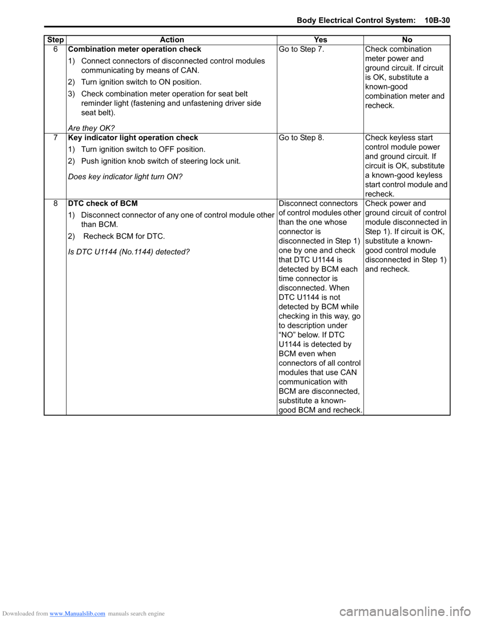
6Combination meter operation check
1) Connect connectors of disconnected control modules
communicating by means of CAN.
2) Turn ignition switch to ON position.
3) Check combination meter operation for seat belt reminder light (fastening and unfastening driver side
seat belt).
Are they OK? Go to Step 7.
Check combination
meter power and
ground circuit. If circuit
is OK, substitute a
known-good
combination meter and
recheck.
7 Key indicator light operation check
1) Turn ignition switch to OFF position.
2) Push ignition knob switch of steering lock unit.
Does key indicator light turn ON? Go to Step 8.
Check keyless start
control module power
and ground circuit. If
circuit is OK, substitute
a known-good keyless
start control module and
recheck.
8 DTC check of BCM
1) Disconnect connector of any one of control module other
than BCM.
2) Recheck BCM for DTC.
Is DTC U1144 (No.1144) detected? Disconnect connectors
of control modules other
than the one whose
connector is
disconnected in Step 1)
one by one and check
that DTC U1144 is
detected by BCM each
time connector is
disconnected. When
DTC U1144 is not
detected by BCM while
checking in this way, go
to description under
“NO” below. If DTC
U1144 is detected by
BCM even when
connectors of all control
modules that use CAN
communication with
BCM are disconnected,
substitute a known-
good BCM and recheck.Check power and
ground circuit of control
module disconnected in
Step 1). If circuit is OK,
substitute a known-
good control module
disconnected in Step 1)
and recheck.
Step
Action YesNo
Page 1444 of 1496
Downloaded from www.Manualslib.com manuals search engine 10C-1 Immobilizer Control System:
Control Systems
Immobilizer Control System
Precautions
Precautions in Diagnosing TroublesS7RS0BA300001
• Before confirming the diagnostic trouble code (DTC),
do not disconnect connector from ECM, battery cable
from battery, ground wire harness, or main fuse. Such
disconnection will erase DTC stored in ECM.
• DTC stored in ECM memory can be checked as well as cleared by using SUZUKI scan tool. Before using
SUZUKI scan tool, read its operator’s manual
carefully to know how to use it and what functions are
available.
• Be sure to read “Precautions for Electrical Circuit Service in Section 00” before inspection.
• Communication of ECM, BCM, keyless start control module (if equipped), ABS / ESP ® control module,
steering angle sensor (ESP ® model), combination
meter and TCM (A/T model) is established by CAN
(Controller Area Network). Therefore, handle CAN
communication lines with care referring to “Precaution
for CAN Communication System in Section 00”. For
CAN communication system, refer to description on
“CAN Communication System Description in Section
1A”.
Precaution in Replacing ECMS7RS0BA300002
• If ECM is replaced with new or used one without immobilizer control function , the engine will not be
started. In case of the above, check if the newly
installed ECM has immobilizer control function.
• After ECM is replaced with new one or used one, the transponder code in the transponder built in the
ignition key has to be registered with ECM. Or, the
engine cannot be started up. For the registration
procedure, refer to “Procedure after ECM
Replacement”.
Precautions in Handling Immobilizer Control
System
S7RS0BA300003
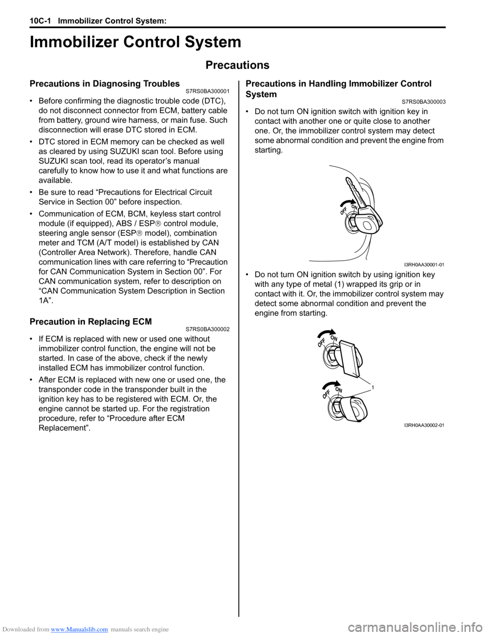
• Do not turn ON ignition sw itch with ignition key in
contact with another one or quite close to another
one. Or, the immobilizer co ntrol system may detect
some abnormal condition and prevent the engine from
starting.
• Do not turn ON ignition switch by using ignition key with any type of metal (1) wrapped its grip or in
contact with it. Or, the i mmobilizer control system may
detect some abnormal condition and prevent the
engine from starting.
I3RH0AA30001-01
1
I3RH0AA30002-01
Page 1445 of 1496
Downloaded from www.Manualslib.com manuals search engine Immobilizer Control System: 10C-2
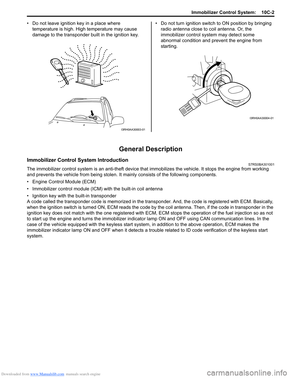
• Do not leave ignition key in a place where
temperature is high. High temperature may cause
damage to the transponder built in the ignition key. • Do not turn ignition switch to ON position by bringing
radio antenna close to coil antenna. Or, the
immobilizer control syst em may detect some
abnormal condition and prevent the engine from
starting.
General Description
Immobilizer Control System IntroductionS7RS0BA301001
The immobilizer control system is an anti-theft device that immobilizes the vehicle. It stops the engine from working
and prevents the vehicle from being stolen. It mainly consists of the following components.
• Engine Control Module (ECM)
• Immobilizer control module (ICM) with the built-in coil antenna
• Ignition key with the built-in transponder
A code called the transponder code is memorized in the tran sponder. And, the code is registered with ECM. Basically,
when the ignition switch is turned ON, ECM reads the code by the coil antenna. Then, if the code in transponder in the
ignition key does not match with the one registered with ECM, ECM stops the operati on of the fuel injection so as not
to start up the engine and turns the immobilizer indi cator lamp ON and OFF using CA N communication lines. In the
case of the vehicle equipped with the keyless start system , in addition to the above operation, ECM makes the
immobilizer indicator lamp ON and OFF when it detects a trouble related to ID code verification of the keyless start
system.
I3RH0AA30003-01
I3RH0AA30004-01
Page 1446 of 1496
Downloaded from www.Manualslib.com manuals search engine 10C-3 Immobilizer Control System:
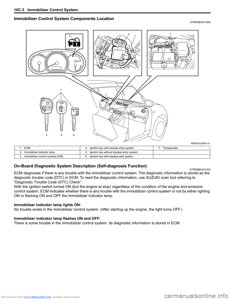
Immobilizer Control System Components LocationS7RS0BA301002
On-Board Diagnostic System Description (Self-diagnosis Function)S7RS0BA301003
ECM diagnoses if there is any trouble with the immobilizer control system. The diagnostic information is stored as the
diagnostic trouble code (DTC) in ECM. To read the di agnostic information, use SUZUKI scan tool referring to
“Diagnostic Trouble Code (DTC) Check”.
With the ignition switch turned ON (but the engine at stop) regardless of the condition of the engine and emission
control system, ECM indicates whether ther e is any trouble with the immobilizer control system or not by either lighting
ON or flashing ON and OFF t he immobilizer indicator lamp.
Immobilizer indicator lamp lights ON:
No trouble exists in the immobilizer control system. (After starting up the engine, the light turns OFF.)
Immobilizer indicator lamp flashes ON and OFF:
There is some trouble in the immo bilizer control system. Its diagnostic information is stored in ECM.
13
4
56
7
2
I6RS0CA30001-01
1. ECM 4. Ignition key with keyless entry system 7. Transponder
2. Immobilizer indicator lamp 5. Ignition key without keyless entry system
3. Immobilizer control module (ICM) 6. Ignition key with keyless start system
Page 1447 of 1496
Downloaded from www.Manualslib.com manuals search engine Immobilizer Control System: 10C-4
Schematic and Routing Diagram
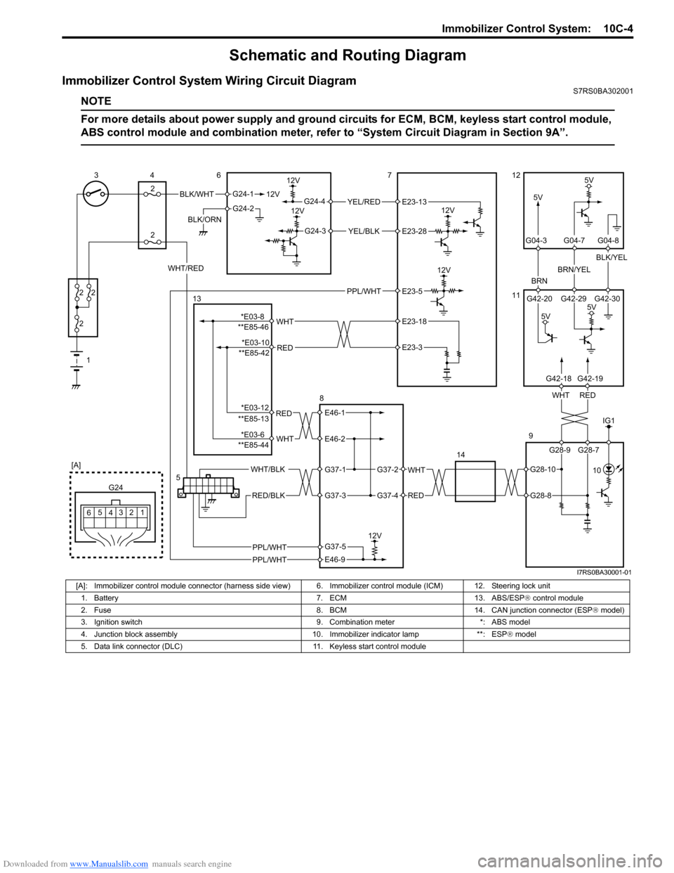
Immobilizer Control System Wiring Circuit DiagramS7RS0BA302001
NOTE
For more details about power supply and ground circuits for ECM, BCM, keyless start control module,
ABS control module and combination meter, refer to “System Ci rcuit Diagram in Section 9A”.
BLK/WHT
BLK/ORN12V
G24-1
G24-2
12V
5V
12V
12VYEL/RED
YEL/BLK
G24-4
G24-3
12V
5V
BRN
BRN/YEL
BLK/YEL
1
2
2 2
2
34
2 6712
11
9
14
12
3
4
G24
[A]
5
6
REDWHT
G42-20 G42-29 G42-30
G04-3 G04-7 G04-8
WHT/RED
5V
5V
5
G28-9 G28-7
G42-18G42-19
E23-13
E23-28
IG1
PPL/WHT 10
PPL/WHT
PPL/WHT
E23-5
RED
WHT**E85-46E23-18
E23-3
RED
WHT
E46-1
E46-2
WHT
RED
G37-2
G37-4
WHT/BLK
RED/BLK
G37-1
G37-3
12V
E46-9
G37-5
13
8
**E85-42
**E85-13
**E85-44
G28-10
G28-8
*E03-8 *E03-10
*E03-12
*E03-6
I7RS0BA30001-01
[A]: Immobilizer control module connector (harness side vi ew) 6. Immobilizer control module (ICM) 12. Steering lock unit
1. Battery 7. ECM 13. ABS/ESP ® control module
2. Fuse 8. BCM 14. CAN junction connector (ESP ® model)
3. Ignition switch 9. Combination meter *: ABS model
4. Junction block assembly 10. Immobilizer indicator lamp **: ESP ® model
5. Data link connector (DLC) 11. Keyless start control module