Page 650 of 1496
Downloaded from www.Manualslib.com manuals search engine 5A-6 Automatic Transmission/Transaxle:
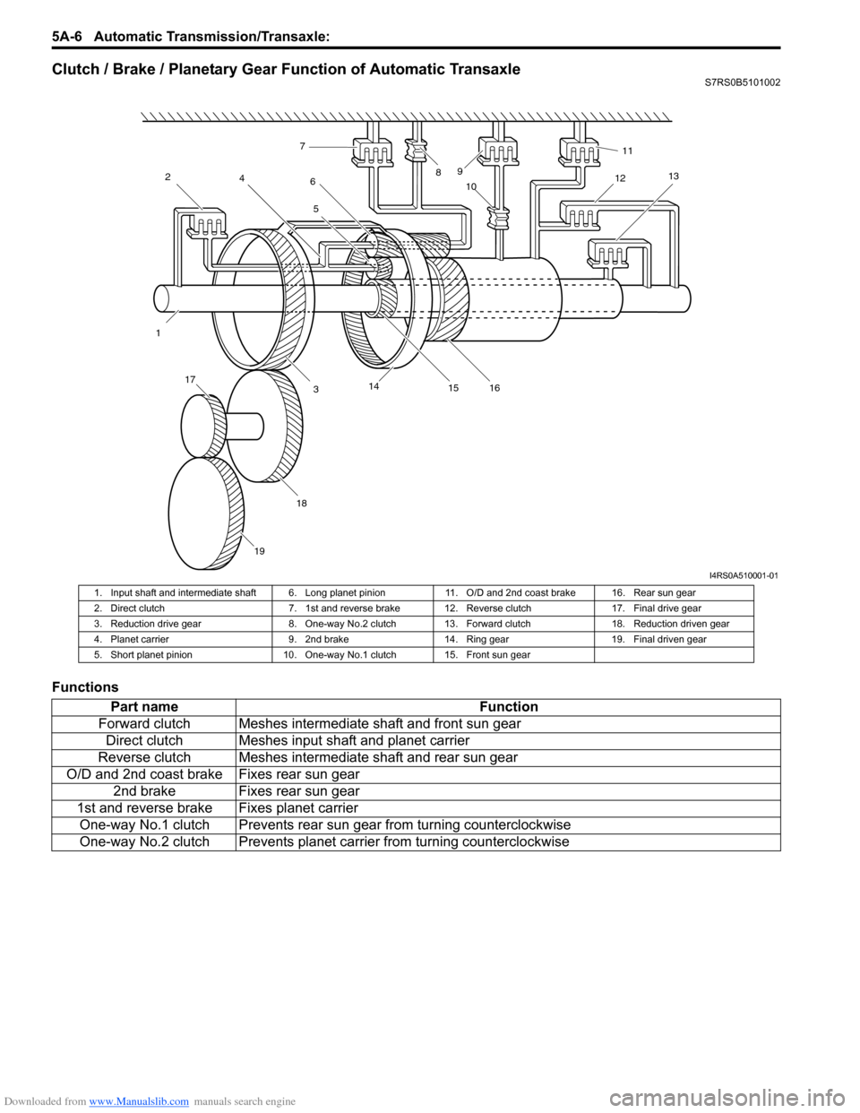
Clutch / Brake / Planetary Gear Function of Automatic TransaxleS7RS0B5101002
Functions
12
4
3 5
6
7
89
10 11
12 13
14 15 16
17
18
19
I4RS0A510001-01
1. Input shaft and intermediate shaft 6. Long planet pi nion 11. O/D and 2nd coast brake 16. Rear sun gear
2. Direct clutch 7. 1st and reverse brak e 12. Reverse clutch 17. Final drive gear
3. Reduction drive gear 8. One-way No.2 clutch 13. Forward clutch 18. Reduction driven gear
4. Planet carrier 9. 2nd brake 14. Ring gear 19. Final driven gear
5. Short planet pinion 10. One-way No.1 clutch 15. Front sun gear
Part name Function
Forward clutch Meshes intermediate shaft and front sun gear Direct clutch Meshes input shaft and planet carrier
Reverse clutch Meshes intermediate shaft and rear sun gear
O/D and 2nd coast brake Fixes rear sun gear 2nd brake Fixes rear sun gear
1st and reverse brake Fixes planet carrier One-way No.1 clutch Prevents rear sun gear from turning counterclockwise
One-way No.2 clutch Prevents planet ca rrier from turning counterclockwise
Page 762 of 1496

Downloaded from www.Manualslib.com manuals search engine 5A-118 Automatic Transmission/Transaxle:
55) Remove one-way clutch outer race retainer (1).
56) Check one-way clutch No.2 as follows.• Ensure planetary carrier (1) rotates only in counterclockwise direction “A”, never in clockwise
direction “B”.
• If the planetary carrier rotates both ways or does not rotate either way, one-way clutch No.2
assembly will need to be replaced with new one-
way clutch No.2 assembly.
57) Remove one-way clutch No.2 assembly (1). 58) Remove planetary gear assembly (1).
59) Measure 1st and reverse brake piston stroke.
If piston stroke exce eds specified value,
disassemble, inspect and replace discs and plates.
• Using special tool, measure 1st and reserve brake piston stroke when compressed air (400 – 800
kPa, 4 – 8 kg/cm
2, 57 – 113 psi) is blown through
oil hole.
Special tool
(A): 09900–20607
(B): 09900–20701
(C): 09952–06020
1st and reverse brake piston stroke
Standard: 0.79 – 1.49 mm (0.031 – 0.059 in.)
I2RH0B510129-01
I2RH0B510130-01
1
I4RS0A510039-01
I2RH0B510132-01
I2RH0B510133-01
Page 798 of 1496

Downloaded from www.Manualslib.com manuals search engine 5A-154 Automatic Transmission/Transaxle:
20) Check for correct installation of planetary gear assembly as follows.
Measure the distance “a” by using micrometer
caliper (1) and straightedge (2). If measured value is
out of specification, remove planetary gear assembly
and reinstall it properly.
Distance between planetary gear assembly and
mating surface of transaxle case
“a”: More than 49.9 m (1.965 in.)
21) Apply A/T fluid to one-way clutch No.2 assembly (1), then install it to planetar y gear assembly. After that,
ensure that planetary carrier rotates only in
counterclockwise direction “A”, not in clockwise
direction “B”. 22) Install one-way clutch outer race retainer (1).
23) Apply A/T fluid to new brake drum gasket (1), then
install it to transaxle case.
24) Apply A/T fluid to 2nd brak e retaining plate (1), discs
(2) and separator plates (3), then install them to
transaxle case.
25) Install 2nd brake return spring subassembly (1) to transaxle case.
“a”
“a”
2 1
I2RH0B510276-01
I2RH0B510277-01
I2RH0B510278-01
I2RH0B510279-01
2
3
1
I2RH0B510280-01
1
I2RH0B510281-01
Page 801 of 1496
Downloaded from www.Manualslib.com manuals search engine Automatic Transmission/Transaxle: 5A-157
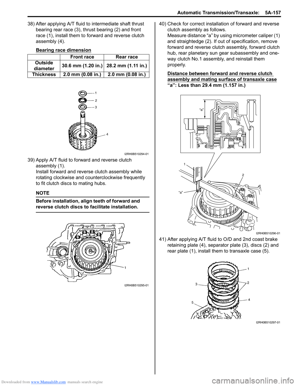
38) After applying A/T fluid to intermediate shaft thrust bearing rear race (3), thrust bearing (2) and front
race (1), install them to forward and reverse clutch
assembly (4).
Bearing race dimension
39) Apply A/T fluid to forward and reverse clutch assembly (1).
Install forward and revers e clutch assembly while
rotating clockwise and co unterclockwise frequently
to fit clutch discs to mating hubs.
NOTE
Before installation, align teeth of forward and
reverse clutch discs to facilitate installation.
40) Check for correct installation of forward and reverse clutch assembly as follows.
Measure distance “a” by using micrometer caliper (1)
and straightedge (2). If out of specification, remove
forward and reverse clutch assembly, forward clutch
hub, rear planetary sun gear subassembly and one-
way clutch No.1 assemb ly, and reinstall them
properly.
Distance between forward and reverse clutch
assembly and mating surface of transaxle case
“a”: Less than 29.4 mm (1.157 in.)
41) After applying A/T fluid to O/D and 2nd coast brake retaining plate (4), separator plate (3), discs (2) and
rear plate (1), install th em to transaxle case (5).
Front race Rear race
Outside
diameter 30.6 mm (1.20 in.) 28.2 mm (1.11 in.)
Thickness 2.0 mm (0.08 in.) 2.0 mm (0.08 in.)
I2RH0B510294-01
I2RH0B510295-01
“a”
“a”
1 2
I2RH0B510296-01
I2RH0B510297-01
Page 804 of 1496
Downloaded from www.Manualslib.com manuals search engine 5A-160 Automatic Transmission/Transaxle:
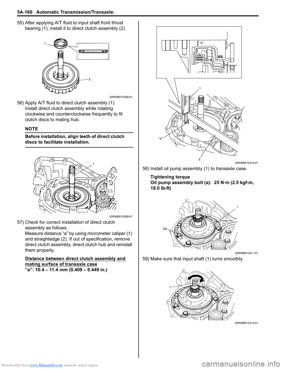
55) After applying A/T fluid to input shaft front thrust bearing (1), install it to direct clutch assembly (2).
56) Apply A/T fluid to direct clutch assembly (1). Install direct clutch a ssembly while rotating
clockwise and counterclockwise frequently to fit
clutch discs to mating hub.
NOTE
Before installation, align teeth of direct clutch
discs to facilitate installation.
57) Check for correct installation of direct clutch assembly as follows.
Measure distance “a” by using micrometer caliper (1)
and straightedge (2). If out of specification, remove
direct clutch assembly, direct clutch hub and reinstall
them properly.
Distance between direct clutch assembly and
mating surface of transaxle case
“a”: 10.4 – 11.4 mm (0.409 – 0.449 in.) 58) Install oil pump assembly
(1) to transaxle case.
Tightening torque
Oil pump assembly bolt (a): 25 N·m (2.5 kgf-m,
18.0 lb-ft)
59) Make sure that input shaft (1) turns smoothly.
I2RH0B510308-01
I2RH0B510309-01
“a”
“a”
1
2
I2RH0B510310-01
I2RH0B510311-01
I2RH0B510312-01
Page 809 of 1496
Downloaded from www.Manualslib.com manuals search engine Automatic Transmission/Transaxle: 5A-165
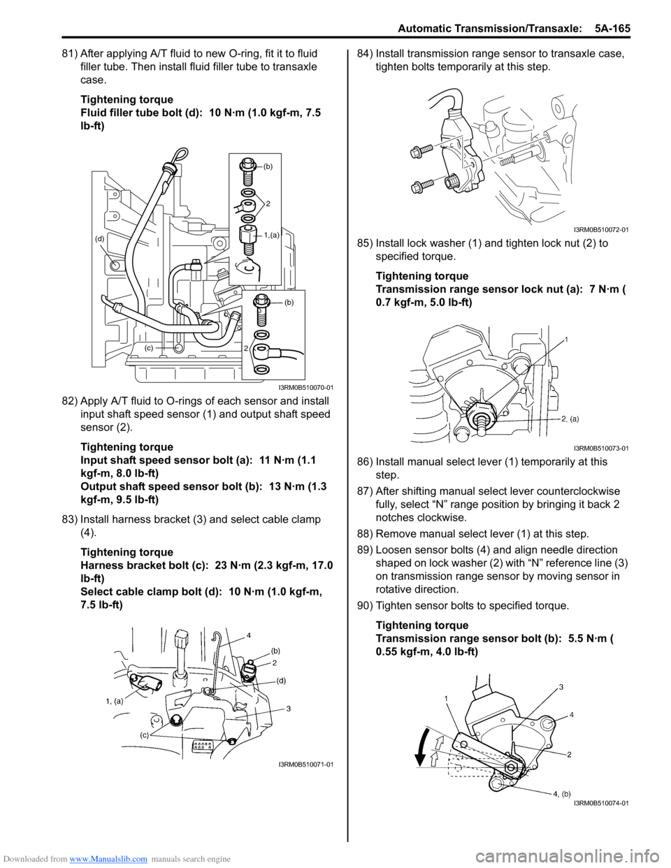
81) After applying A/T fluid to new O-ring, fit it to fluid filler tube. Then install fl uid filler tube to transaxle
case.
Tightening torque
Fluid filler tube bolt (d): 10 N·m (1.0 kgf-m, 7.5
lb-ft)
82) Apply A/T fluid to O-rings of each sensor and install input shaft speed sensor (1) and output shaft speed
sensor (2).
Tightening torque
Input shaft speed sensor bolt (a): 11 N·m (1.1
kgf-m, 8.0 lb-ft)
Output shaft speed sensor bolt (b): 13 N·m (1.3
kgf-m, 9.5 lb-ft)
83) Install harness bracket (3) and select cable clamp (4).
Tightening torque
Harness bracket bolt (c): 23 N·m (2.3 kgf-m, 17.0
lb-ft)
Select cable clamp bolt (d): 10 N·m (1.0 kgf-m,
7.5 lb-ft) 84) Install transmission range sensor to transaxle case,
tighten bolts temporarily at this step.
85) Install lock washer (1) and tighten lock nut (2) to specified torque.
Tightening torque
Transmission range sensor lock nut (a): 7 N·m (
0.7 kgf-m, 5.0 lb-ft)
86) Install manual select leve r (1) temporarily at this
step.
87) After shifting manual se lect lever counterclockwise
fully, select “N” range position by bringing it back 2
notches clockwise.
88) Remove manual select lever (1) at this step.
89) Loosen sensor bolts (4) and align needle direction shaped on lock washer (2) with “N” reference line (3)
on transmission range sensor by moving sensor in
rotative direction.
90) Tighten sensor bolts to specified torque.
Tightening torque
Transmission range sensor bolt (b): 5.5 N·m (
0.55 kgf-m, 4.0 lb-ft)
(c)
(d)
(b)
2
1,(a)
(b)
2
I3RM0B510070-01
I3RM0B510071-01
I3RM0B510072-01
I3RM0B510073-01
I3RM0B510074-01
Page 831 of 1496

Downloaded from www.Manualslib.com manuals search engine Manual Transmission/Transaxle: 5B-17
5) Remove gear shift locating bolts (1) with washers,
then take out locating springs and steel balls.
6) Remove back up light switch (2).
7) Remove reverse shaft bolt (2) with washer.
8) Remove case bolts (1) from outside and another bolts from clutch housing side.
9) Tapping left case flanges with plastic hammer, remove left case (3).
10) Pull out reverse gear shaft (1) with washer (2), then take off reverse idler gear (3).
11) Remove reverse gear shift lever bolts (4) and reverse gear shift lever (5).
12) Pull out 5th & reverse gear shift guide shaft (6) together with 5th & reverse gear shift shaft (7). 13) Tapping input shaft end with plastic hammer, push it
out as assembly from case a little, then take out
input shaft assembly (1), countershaft assembly (2),
high speed gear shift shaft (3) and low speed gear
shift shaft (4) all at once.
14) Remove countershaft left bearing outer race from left case (1) using special tool.
Special tool
(A): 09913–70123
15) Remove side bearing retainer bolts.
16) Turn side bearing retainer (1) counterclockwise until it stops, and remove side bearing retainer using 2 flat
end rods (2) or the like.
17) Remove O-ring from side bearing retainer.
I2RH01520032-01
I4RS0A520032-01
I4RS0A520033-01
I2RH01520035-01
(A)
1
I4RH01520021-01
1
2
2
I4RS0A520034-01
Page 858 of 1496
Downloaded from www.Manualslib.com manuals search engine 5C-6 Clutch:
Clutch Fluid Pipe Removal and InstallationS7RS0B5306007
Removal
CAUTION!
Do not allow fluid to get on painted surface. It
may cause painted surface damage.
1) Remove dust and dirt from each joint of pipe to be disconnected and clean around brake master
cylinder reservoir cap.
2) Take out fluid with syringe or such from brake master cylinder reservoir.
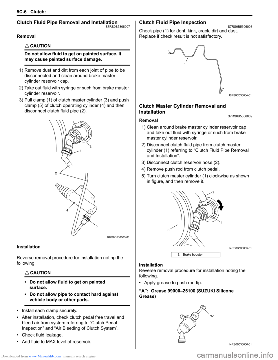
3) Pull clamp (1) of clutch master cylinder (3) and push clamp (5) of clutch operating cylinder (4) and then
disconnect clutch fluid pipe (2).
Installation
Reverse removal procedure for installation noting the
following.
CAUTION!
• Do not allow fluid to get on painted surface.
• Do not allow pipe to contact hard against vehicle body or other parts.
• Install each clamp securely.
• After installation, check clutch pedal free travel and bleed air from system referring to “Clutch Pedal
Inspection” and “Air Blee ding of Clutch System”.
• Check fluid leakage.
• Add fluid to MAX level of reservoir.
Clutch Fluid Pipe InspectionS7RS0B5306008
Check pipe (1) for dent, kink, crack, dirt and dust.
Replace if check result is not satisfactory.
Clutch Master Cylinder Removal and
Installation
S7RS0B5306009
Removal 1) Clean around brake master cylinder reservoir cap and take out fluid with syringe or such from brake
master cylinder reservoir.
2) Disconnect clutch fluid pipe from clutch master cylinder (1) referring to “C lutch Fluid Pipe Removal
and Installation”.
3) Disconnect clutch reservoir hose (2).
4) Remove push rod from clutch pedal.
5) Turn clutch master cylinder (1) clockwise as shown in figure, and then remove it.
Installation
Reverse removal procedure for installation noting the
following.
• Apply grease to push rod tip.
“A”: Grease 99000–25100 (SUZUKI Silicone
Grease)
31
2
5
4
I4RS0B530003-01
3. Brake booster
1
I6RS0C530004-01
1
2
3
I4RS0B530005-01
“A”
I4RS0B530006-01