2004 SUZUKI SWIFT change time
[x] Cancel search: change timePage 1033 of 1496
Downloaded from www.Manualslib.com manuals search engine Seat Belts: 8A-2
Seat Belt with ELR
The seat belt with emergency locking retractor (ELR) is
designed so that it locks immediately (to prevent the
webbing from being pulled out of the retractor any
further) when any of the following items is detected as
exceeding each set value;
• Speed at which the webbing is pulled out of the retractor.
• Acceleration or deceleration of the vehicle speed.
• Inclination.
Seat Belt with A-ELR
The automatic and emergency locking retractor (A-ELR)
works as an Emergency Locking Retractor (ELR) till its
webbing is pulled all the way out and then on as an
Automatic Locking Retractor (ALR ) till it is retracted fully.
ALR: Automatically locks when the webbing is pulled out
from the retractor and allowed to retract even a little.
Then the webbing can not be pulled out any further,
unless it is wound all the way back into the retractor,
which releases the lock and allows the webbing to be
pulled out.
Seat Belt with ELR and Pretensioner
The seat belt with ELR and a pretensioner has a
pretensioner mechanism whic h operates in linkage with
the air bag in addition to the described ELR.
The pretensioner is incorporated in retractor assembly
and controlled by SDM as one of air bag system
components. It will be activated at the same time as the
driver and passenger air bag module when an impact at
the front of vehicle exceeds the specified value.
When servicing seat belt (retractor assembly) with
pretensioner, be sure to observe all WARNINGS and
CAUTIONS and “Precautions on Service and Diagnosis
of Air Bag System in Section 8B”. CAUTION!
Do not reuse the seat belt pretensioner
(retractor assembly) that has activated.
Replace it with a new seat belt assembly and
buckle together as a set. For checking
procedure of its activation, refer to “Repair
and Inspection Required after Accident in
Section 8B”.
Seat Belt Remainder
When driver’s seat belt is unfastened (under the
following conditions), seat belt reminder light and
warning buzzer inform that driver’s seat belt is
unfastened. Seat belt reminder light located in
combination meter and warning buzzer located inside
BCM operate as follows:
• Seat belt reminder light comes on when driver’s seat belt is unfastened while igni tion key switch is at ON
position.
• If vehicle speed exceeds 15 km/h with seat belt unfastened, warning buzzer operates for
approximately 95 seconds and seat belt reminder light
flashes synchronously with buzzer. When warning
buzzer stops operating, seat belt reminder light is
turned on.
• If driver’s seat belt state is changed from “fastened” to “unfastened” while vehicle speed is above 15 km/h,
warning buzzer operates for approximately 95
seconds and seat belt reminder light flashes
synchronously with buzzer. When warning buzzer
stops operating, seat belt reminder light is turned on.
Diagnostic Information and Procedures
Repair and Inspection Required after AccidentS7RS0B8104001
After an accident, whether the seat belt pretensioner has been activated or not, be sure to perform checks and repairs
described on “Repair and Inspection Required after Accident in Section 8B”.
Page 1307 of 1496
Downloaded from www.Manualslib.com manuals search engine Instrumentation / Driver Info. / Horn: 9C-12
Clock Symptom Diagnosis (If Equipped)S7RS0B9304016
Audio System Symptom Diagnosis (If Equipped)S7RS0B9304017
Radio
NOTE
Electronic part / system with undiagnosed pr oblem may cause electromagnetic interference.
Electromagnetic interference condition may have poor radio reception. To test for presence of
electromagnetic interference in part / system, perform the following procedures.
1. Turn ignition switch to OFF.
2. Systematically disconnect the electronic part / system connector(s) one at a time.
3. Turn ignition switch to ON.
4. Check any improvement in radio reception.
Display of fuel
consumption does not
change at “– – – l / 100 km
(km/l, MPG)” Vehicle is not running (instantaneous
fuel consumption mode)
—
Fuel consumption was reset (average
fuel consumption mo de, if equipped)Vehicle runs for a while.
Vehicle speed signal faulty Check ECM for DTC referring to “DTC Check
in Section 1A”.
Wiring and/or grounding faulty Repair as necessary.
ECM faulty Check input and output signal of ECM referring
to “Inspection of ECM and Its Circuits in
Section 1A”.
Information display unit faulty Replace unit.
BCM faulty Replace after making sure that none of above
parts is faulty.
Condition Possible cause Correction / Reference Item
Condition
Possible cause Correction / Reference Item
No displaying of clock Circuit fuse Blown Replace fuse and check for short circuit.
Wiring and/or grounding faulty Repair as necessary.
Clock unit faulty Replace unit.
ConditionPossible cause Correction / Reference Item
Poor radio reception Out of service area (Poor location) —
Antenna faulty Replace antenna.
Electrical part / system faulty Repair or replace electrical part / system
referring to after-mentioned NOTE.
Wiring and/or grounding faulty Repair as necessary.
Radio assembly faulty Replace radio assembly.
Radio does not operate
and speaker does not
sound Circuit fuse(s) blown
Replace fuse(s) and check for short circuit.
Wiring and/or grounding faulty Repair as necessary.
Radio assembly faulty Replace radio assembly.
Radio does not operate,
but speaker sound Wiring and/or grounding faulty
Repair as necessary.
Radio assembly faulty Replace radio assembly.
Radio is operative, but all
speakers does not sound Wiring and/or grounding faulty
Repair as necessary.
Radio assembly faulty Replace radio assembly.
Individual speaker is
noisy or inoperative Wiring and/or grounding faulty
Repair as necessary.
Speaker faulty Replace speaker.
Radio assembly faulty Replace radio assembly.
Sound quality is poor Out of service area (Poor location) —
Speaker installed incorrectly Install correctly.
Wiring and/or grounding faulty Repair as necessary.
Speaker faulty Replace speaker.
Radio assembly faulty Replace radio assembly.
Page 1325 of 1496
Downloaded from www.Manualslib.com manuals search engine Wipers / Washers: 9D-8
4) Remove windshield wiper and washer switch (1) from combination swit ch assembly (2) and
disconnect its coupler (3).
Installation
Reverse removal procedure.
Windshield Wiper and Washer Switch
Inspection
S7RS0B9406009
Windshield Wiper and Washer Switch
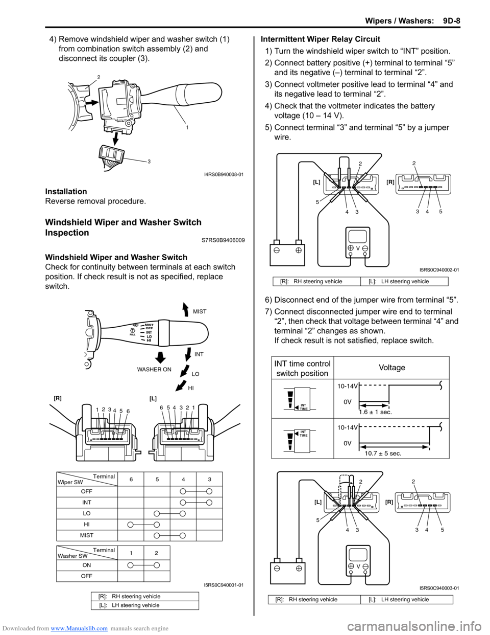
Check for continuity between terminals at each switch
position. If check result is not as specified, replace
switch. Intermittent Wiper Relay Circuit
1) Turn the windshield wiper switch to “INT” position.
2) Connect battery positive (+ ) terminal to terminal “5”
and its negative (–) terminal to terminal “2”.
3) Connect voltmeter positive lead to terminal “4” and its negative lead to terminal “2”.
4) Check that the voltmeter indicates the battery voltage (10 – 14 V).
5) Connect terminal “3” and terminal “5” by a jumper wire.
6) Disconnect end of the jumper wire from terminal “5”.
7) Connect disconnected jumper wire end to terminal “2”, then check that voltage between terminal “4” and
terminal “2” changes as shown.
If check result is not satisfied, replace switch.
[R]: RH steering vehicle
[L]: LH steering vehicle
1
2
3
I4RS0B940008-01
Terminal
Wiper SW
OFF
INT 6543
MIST
Terminal
Washer SW
OFF 12
ONLO
HI
654321
MIST
INT
LO
HI
WASHER ON
1
2
3
4 5 6
[R]
[L]
I5RS0C940001-01
[R]: RH steering vehicle [L]: LH steering vehicle
[R]: RH steering vehicle [L]: LH steering vehicle
V
2
34
52
34 5
[L] [R]
I5RS0C940002-01
V
INT
TIME
INT
TIME
INT time control
switch position Voltage
10-14V
0V 1.6 ± 1 sec.
10-14V
0V 10.7 ± 5 sec.
2
34
52
34 5
[L]
[R]
I5RS0C940003-01
Page 1360 of 1496
Downloaded from www.Manualslib.com manuals search engine 9F-14 Security and Locks:
Keyless Entry Answer Back Function Change-
over Procedure (If Equipped)
S7RS0B9606016
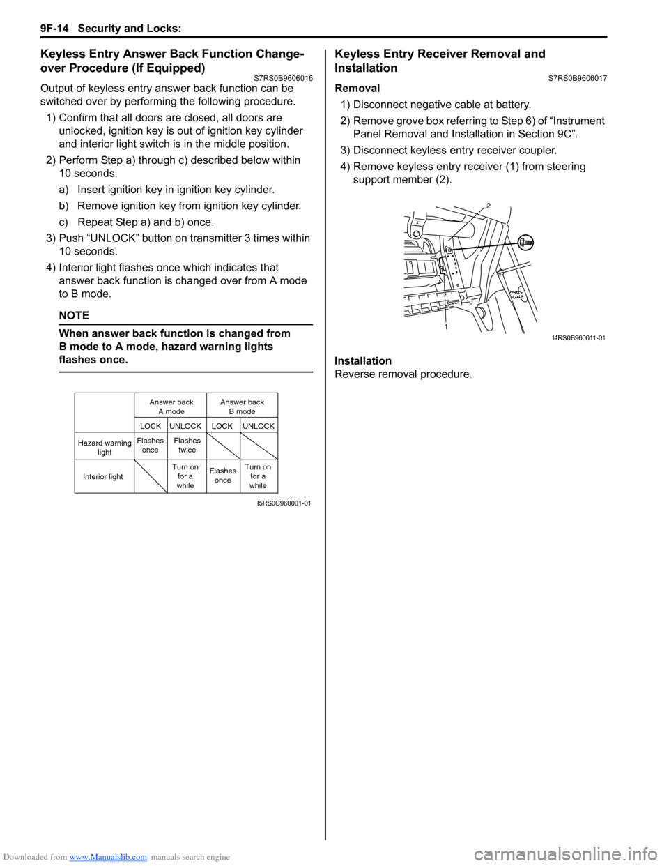
Output of keyless entry answer back function can be
switched over by performing the following procedure.
1) Confirm that all doors are closed, all doors are unlocked, ignition key is out of ignition key cylinder
and interior light switch is in the middle position.
2) Perform Step a) through c) described below within 10 seconds.
a) Insert ignition key in ignition key cylinder.
b) Remove ignition key from ignition key cylinder.
c) Repeat Step a) and b) once.
3) Push “UNLOCK” button on transmitter 3 times within 10 seconds.
4) Interior light flashes once which indicates that answer back function is changed over from A mode
to B mode.
NOTE
When answer back function is changed from
B mode to A mode, hazard warning lights
flashes once.
Keyless Entry Receiver Removal and
Installation
S7RS0B9606017
Removal
1) Disconnect negative cable at battery.
2) Remove grove box referring to Step 6) of “Instrument Panel Removal and Installation in Section 9C”.
3) Disconnect keyless entry receiver coupler.
4) Remove keyless entry receiver (1) from steering support member (2).
Installation
Reverse removal procedure.
Hazard warning light
LOCK LOCK
UNLOCK UNLOCK
Interior lightFlashes
once Flashes
twice
Flashesonce
Turn on
for a
while Turn on
for a
while
Answer back
A mode Answer back
B mode
I5RS0C960001-01
1 2I4RS0B960011-01
Page 1442 of 1496
Downloaded from www.Manualslib.com manuals search engine 10B-39 Body Electrical Control System:
Repair Instructions
BCM (Included in Junction Block Assembly)
Removal and Installation
S7RS0BA206001
CAUTION!
Do not attempt removal of BCM from junction
block assembly as it may cause contact
failure.
If there is faulty condition in BCM, replace
junction block assembly.
Removal
1) Disconnect negative (–) cable from battery.
2) Disable air bag system referring to “Disabling Air Bag System in Section 8B”.
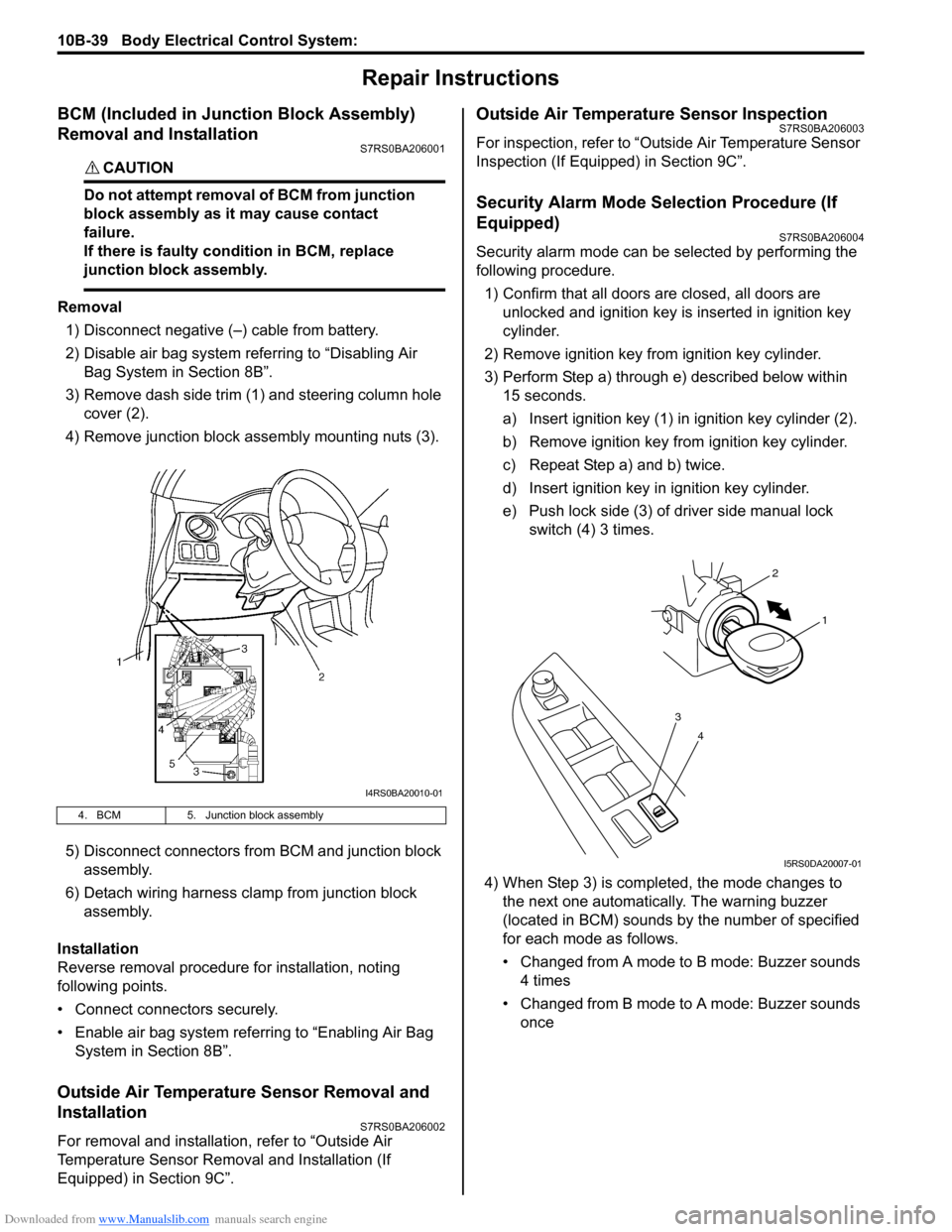
3) Remove dash side trim (1) and steering column hole cover (2).
4) Remove junction block assembly mounting nuts (3).
5) Disconnect connectors from BCM and junction block assembly.
6) Detach wiring harness clamp from junction block assembly.
Installation
Reverse removal procedure for installation, noting
following points.
• Connect connectors securely.
• Enable air bag system referring to “Enabling Air Bag System in Section 8B”.
Outside Air Temperature Sensor Removal and
Installation
S7RS0BA206002
For removal and installation, refer to “Outside Air
Temperature Sensor Removal and Installation (If
Equipped) in Section 9C”.
Outside Air Temperature Sensor InspectionS7RS0BA206003
For inspection, refer to “Outside Air Temperature Sensor
Inspection (If Equipped) in Section 9C”.
Security Alarm Mode Selection Procedure (If
Equipped)
S7RS0BA206004
Security alarm mode can be selected by performing the
following procedure.
1) Confirm that all doors are closed, all doors are unlocked and ignition key is inserted in ignition key
cylinder.
2) Remove ignition key from ignition key cylinder.
3) Perform Step a) through e) described below within 15 seconds.
a) Insert ignition key (1) in ignition key cylinder (2).
b) Remove ignition key from ignition key cylinder.
c) Repeat Step a) and b) twice.
d) Insert ignition key in ignition key cylinder.
e) Push lock side (3) of driver side manual lock switch (4) 3 times.
4) When Step 3) is completed, the mode changes to the next one automatically. The warning buzzer
(located in BCM) sounds by the number of specified
for each mode as follows.
• Changed from A mode to B mode: Buzzer sounds 4 times
• Changed from B mode to A mode: Buzzer sounds once
4. BCM 5. Junction block assembly
I4RS0BA20010-01
4
3
1
2
I5RS0DA20007-01
Page 1473 of 1496
Downloaded from www.Manualslib.com manuals search engine Keyless Start System: 10E-11
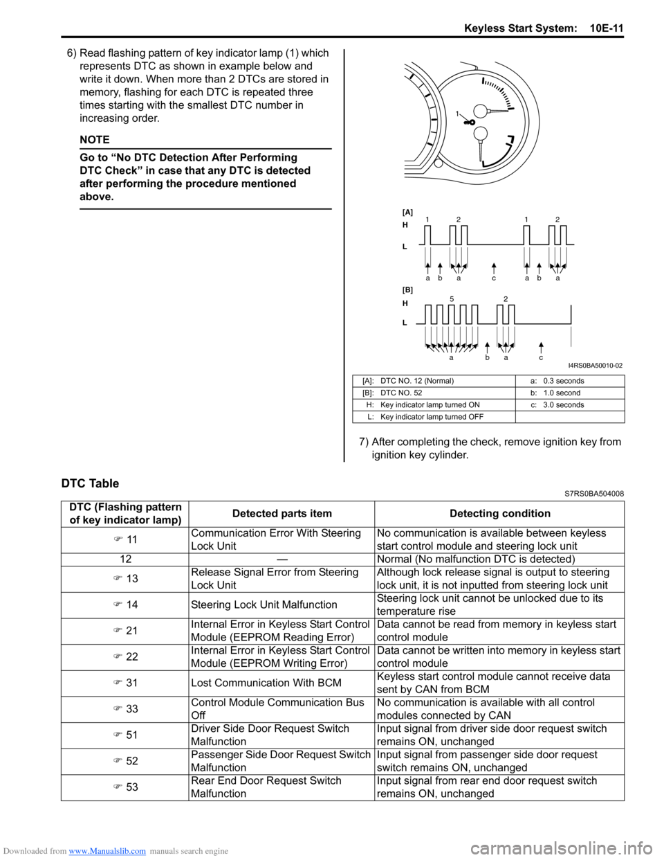
6) Read flashing pattern of key indicator lamp (1) which represents DTC as shown in example below and
write it down. When more than 2 DTCs are stored in
memory, flashing for each DTC is repeated three
times starting with the smallest DTC number in
increasing order.
NOTE
Go to “No DTC Detect ion After Performing
DTC Check” in case that any DTC is detected
after performing the procedure mentioned
above.
7) After completing the check, remove ignition key from ignition key cylinder.
DTC TableS7RS0BA504008
[A]: DTC NO. 12 (Normal)
a: 0.3 seconds
[B]: DTC NO. 52 b: 1.0 second
H: Key indicator lamp tu rned ONc: 3.0 seconds
L: Key indicator lamp turned OFF
bc
a
a
[A]
H
L
H
L [B]
52
bac
a
2
11baa 2
1
I4RS0BA50010-02
DTC (Flashing pattern
of key indicator lamp) Detected parts item Detecting condition
�) 11 Communication Error With Steering
Lock Unit No communication is available between keyless
start control module and steering lock unit
12 — Normal (No malfunct ion DTC is detected)
�) 13 Release Signal Error from Steering
Lock Unit Although lock release signal is output to steering
lock unit, it is not inputt
ed from steering lock unit
�) 14 Steering Lock Unit Malfunction Steering lock unit cannot be unlocked due to its
temperature rise
�) 21 Internal Error in Ke
yless Start Control
Module (EEPROM Reading Error) Data cannot be read from memory in keyless start
control module
�) 22 Internal Error in Ke
yless Start Control
Module (EEPROM Writing Error) Data cannot be written into memory in keyless start
control module
�) 31 Lost Communication With BCM Keyless start control module cannot receive data
sent by CAN from BCM
�) 33 Control Module Communication Bus
Off No communication is available with all control
modules connected by CAN
�) 51 Driver Side Door Request Switch
Malfunction Input signal from driver side door request switch
remains ON, unchanged
�) 52 Passenger Side Door Request Switch
Malfunction Input signal from passenger side door request
switch remains ON, unchanged
�) 53 Rear End Door Request Switch
Malfunction Input signal from rear end door request switch
remains ON, unchanged