Page 1310 of 1496
Downloaded from www.Manualslib.com manuals search engine 9C-15 Instrumentation / Driver Info. / Horn:
Combination Meter Removal and InstallationS7RS0B9306003
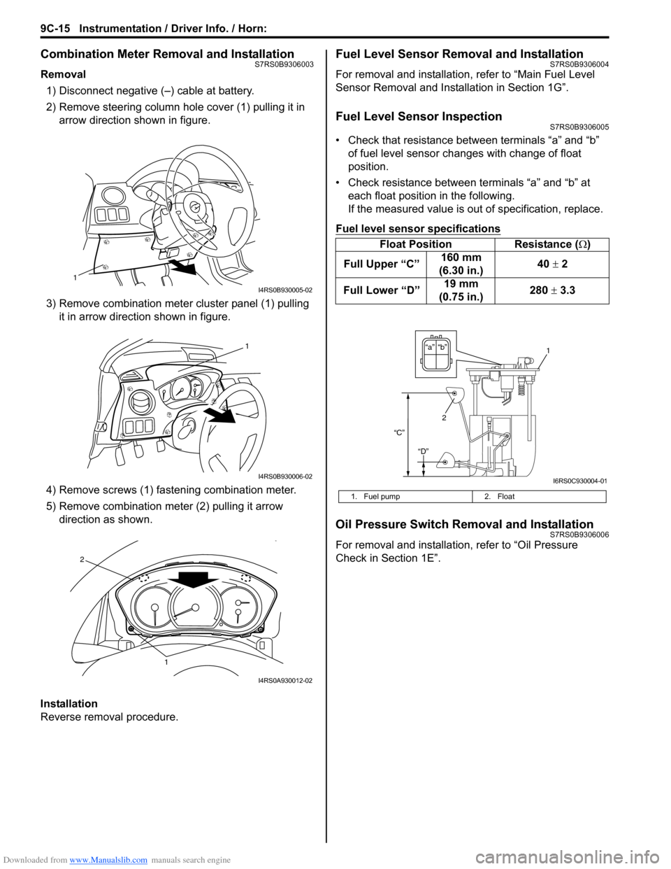
Removal1) Disconnect negative (–) cable at battery.
2) Remove steering column hole cover (1) pulling it in arrow direction shown in figure.
3) Remove combination mete r cluster panel (1) pulling
it in arrow direction shown in figure.
4) Remove screws (1) fast ening combination meter.
5) Remove combination me ter (2) pulling it arrow
direction as shown.
Installation
Reverse removal procedure.
Fuel Level Sensor Removal and InstallationS7RS0B9306004
For removal and installation, refer to “Main Fuel Level
Sensor Removal and Installation in Section 1G”.
Fuel Level Sensor InspectionS7RS0B9306005
• Check that resistance between terminals “a” and “b” of fuel level sensor changes with change of float
position.
• Check resistance between terminals “a” and “b” at each float position in the following.
If the measured value is out of specification, replace.
Fuel level sensor specifications
Oil Pressure Switch Removal and InstallationS7RS0B9306006
For removal and installation , refer to “Oil Pressure
Check in Section 1E”.
1
I4RS0B930005-02
1
I4RS0B930006-02
1
2
I4RS0A930012-02
Float Position Resistance (Ω)
Full Upper “C” 160 mm
(6.30 in.) 40
± 2
Full Lower “D” 19 mm
(0.75 in.) 280
± 3.3
1. Fuel pump 2. Float
“b”“a”
2
“C”
“D”
1
I6RS0C930004-01
Page 1325 of 1496
Downloaded from www.Manualslib.com manuals search engine Wipers / Washers: 9D-8
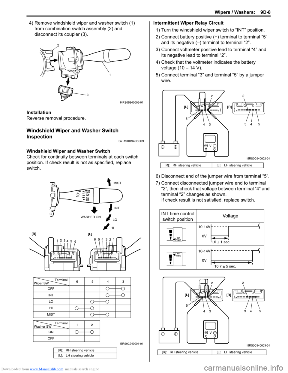
4) Remove windshield wiper and washer switch (1) from combination swit ch assembly (2) and
disconnect its coupler (3).
Installation
Reverse removal procedure.
Windshield Wiper and Washer Switch
Inspection
S7RS0B9406009
Windshield Wiper and Washer Switch
Check for continuity between terminals at each switch
position. If check result is not as specified, replace
switch. Intermittent Wiper Relay Circuit
1) Turn the windshield wiper switch to “INT” position.
2) Connect battery positive (+ ) terminal to terminal “5”
and its negative (–) terminal to terminal “2”.
3) Connect voltmeter positive lead to terminal “4” and its negative lead to terminal “2”.
4) Check that the voltmeter indicates the battery voltage (10 – 14 V).
5) Connect terminal “3” and terminal “5” by a jumper wire.
6) Disconnect end of the jumper wire from terminal “5”.
7) Connect disconnected jumper wire end to terminal “2”, then check that voltage between terminal “4” and
terminal “2” changes as shown.
If check result is not satisfied, replace switch.
[R]: RH steering vehicle
[L]: LH steering vehicle
1
2
3
I4RS0B940008-01
Terminal
Wiper SW
OFF
INT 6543
MIST
Terminal
Washer SW
OFF 12
ONLO
HI
654321
MIST
INT
LO
HI
WASHER ON
1
2
3
4 5 6
[R]
[L]
I5RS0C940001-01
[R]: RH steering vehicle [L]: LH steering vehicle
[R]: RH steering vehicle [L]: LH steering vehicle
V
2
34
52
34 5
[L] [R]
I5RS0C940002-01
V
INT
TIME
INT
TIME
INT time control
switch position Voltage
10-14V
0V 1.6 ± 1 sec.
10-14V
0V 10.7 ± 5 sec.
2
34
52
34 5
[L]
[R]
I5RS0C940003-01
Page 1326 of 1496
Downloaded from www.Manualslib.com manuals search engine 9D-9 Wipers / Washers:
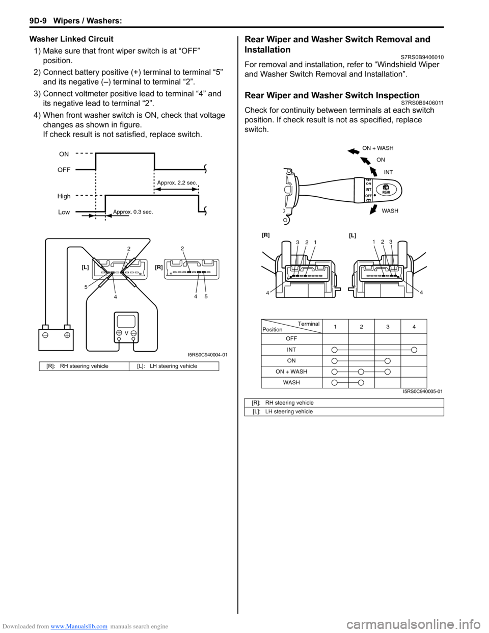
Washer Linked Circuit1) Make sure that front wiper switch is at “OFF” position.
2) Connect battery positive (+ ) terminal to terminal “5”
and its negative (–) terminal to terminal “2”.
3) Connect voltmeter positive lead to terminal “4” and its negative lead to terminal “2”.
4) When front washer switch is ON, check that voltage
changes as shown in figure.
If check result is not satisfied, replace switch.Rear Wiper and Washer Switch Removal and
Installation
S7RS0B9406010
For removal and installation, refer to “Windshield Wiper
and Washer Switch Removal and Installation”.
Rear Wiper and Washer Switch InspectionS7RS0B9406011
Check for continuity between terminals at each switch
position. If check result is not as specified, replace
switch.
[R]: RH steering vehicle [L]: LH steering vehicle
V
2
4
52
45
[L] [R]
ON
OFF
High Low
Approx. 0.3 sec. Approx. 2.2 sec.
I5RS0C940004-01
[R]: RH steering vehicle
[L]: LH steering vehicle
Terminal
Position
OFF
INT 4
3
12
WASH ON
ON + WASH
ON + WASH
INT
ON
WASH
123
4
[R]
[L]123
4
I5RS0C940005-01
Page 1360 of 1496
Downloaded from www.Manualslib.com manuals search engine 9F-14 Security and Locks:
Keyless Entry Answer Back Function Change-
over Procedure (If Equipped)
S7RS0B9606016
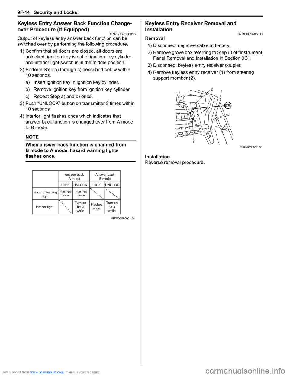
Output of keyless entry answer back function can be
switched over by performing the following procedure.
1) Confirm that all doors are closed, all doors are unlocked, ignition key is out of ignition key cylinder
and interior light switch is in the middle position.
2) Perform Step a) through c) described below within 10 seconds.
a) Insert ignition key in ignition key cylinder.
b) Remove ignition key from ignition key cylinder.
c) Repeat Step a) and b) once.
3) Push “UNLOCK” button on transmitter 3 times within 10 seconds.
4) Interior light flashes once which indicates that answer back function is changed over from A mode
to B mode.
NOTE
When answer back function is changed from
B mode to A mode, hazard warning lights
flashes once.
Keyless Entry Receiver Removal and
Installation
S7RS0B9606017
Removal
1) Disconnect negative cable at battery.
2) Remove grove box referring to Step 6) of “Instrument Panel Removal and Installation in Section 9C”.
3) Disconnect keyless entry receiver coupler.
4) Remove keyless entry receiver (1) from steering support member (2).
Installation
Reverse removal procedure.
Hazard warning light
LOCK LOCK
UNLOCK UNLOCK
Interior lightFlashes
once Flashes
twice
Flashesonce
Turn on
for a
while Turn on
for a
while
Answer back
A mode Answer back
B mode
I5RS0C960001-01
1 2I4RS0B960011-01
Page 1442 of 1496
Downloaded from www.Manualslib.com manuals search engine 10B-39 Body Electrical Control System:
Repair Instructions
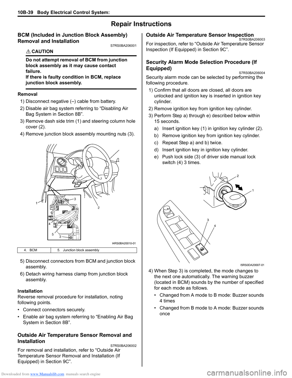
BCM (Included in Junction Block Assembly)
Removal and Installation
S7RS0BA206001
CAUTION!
Do not attempt removal of BCM from junction
block assembly as it may cause contact
failure.
If there is faulty condition in BCM, replace
junction block assembly.
Removal
1) Disconnect negative (–) cable from battery.
2) Disable air bag system referring to “Disabling Air Bag System in Section 8B”.
3) Remove dash side trim (1) and steering column hole cover (2).
4) Remove junction block assembly mounting nuts (3).
5) Disconnect connectors from BCM and junction block assembly.
6) Detach wiring harness clamp from junction block assembly.
Installation
Reverse removal procedure for installation, noting
following points.
• Connect connectors securely.
• Enable air bag system referring to “Enabling Air Bag System in Section 8B”.
Outside Air Temperature Sensor Removal and
Installation
S7RS0BA206002
For removal and installation, refer to “Outside Air
Temperature Sensor Removal and Installation (If
Equipped) in Section 9C”.
Outside Air Temperature Sensor InspectionS7RS0BA206003
For inspection, refer to “Outside Air Temperature Sensor
Inspection (If Equipped) in Section 9C”.
Security Alarm Mode Selection Procedure (If
Equipped)
S7RS0BA206004
Security alarm mode can be selected by performing the
following procedure.
1) Confirm that all doors are closed, all doors are unlocked and ignition key is inserted in ignition key
cylinder.
2) Remove ignition key from ignition key cylinder.
3) Perform Step a) through e) described below within 15 seconds.
a) Insert ignition key (1) in ignition key cylinder (2).
b) Remove ignition key from ignition key cylinder.
c) Repeat Step a) and b) twice.
d) Insert ignition key in ignition key cylinder.
e) Push lock side (3) of driver side manual lock switch (4) 3 times.
4) When Step 3) is completed, the mode changes to the next one automatically. The warning buzzer
(located in BCM) sounds by the number of specified
for each mode as follows.
• Changed from A mode to B mode: Buzzer sounds 4 times
• Changed from B mode to A mode: Buzzer sounds once
4. BCM 5. Junction block assembly
I4RS0BA20010-01
4
3
1
2
I5RS0DA20007-01
Page:
< prev 1-8 9-16 17-24