2004 SUZUKI SWIFT oil type
[x] Cancel search: oil typePage 401 of 1496
Downloaded from www.Manualslib.com manuals search engine Ignition System: 1H-9
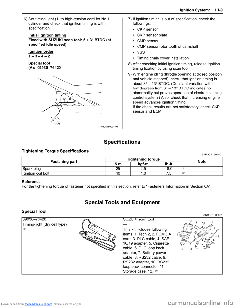
6) Set timing light (1) to high-tension cord for No.1 cylinder and check that ignition timing is within
specification.
Initial ignition timing
Fixed with SUZUKI scan tool: 5 ± 3° BTDC (at
specified idle speed)
Ignition order
1 – 3 – 4 – 2
Special tool
(A): 09930–76420 7) If ignition timing is out
of specification, check the
followings.
• CKP sensor
• CKP sensor plate
• CMP sensor
• CMP sensor rotor tooth of camshaft
• VSS
• Timing chain cover installation
8) After checking initial igniti on timing, release ignition
timing fixation by using scan tool.
9) With engine idling (throttl e opening at closed position
and vehicle stopped), check that ignition timing is
about 3 ° – 13° BTDC. (Constant variation within a
few degrees from 3 ° – 13° BTDC indicates no
abnormality but proves operation of electronic timing
control system.) Also, check that increasing engine
speed advances ignition timing.
If the check results are not satisfactory, check CKP
sensor and ECM.
Specifications
Tightening Torque SpecificationsS7RS0B1807001
Reference:
For the tightening torque of fastener not specified in this section, refer to “Fasteners Information in Section 0A”.
Special Tools and Equipment
Special ToolS7RS0B1808001
1, (A)10
0I3RB0A180004-01
Fastening part Tightening torque
Note
N ⋅mkgf-mlb-ft
Spark plug 25 2.5 18.0 �)
Ignition coil bolt 10 1.0 7.5 �)
09930–76420SUZUKI scan tool
Timing-light (dry cell type) —
�) This kit includes following
items. 1. Tech 2, 2. PCMCIA
card, 3. DLC cable, 4. SAE
16/19 adapter, 5. Cigarette
cable, 6. DLC loop back
adapter, 7. Battery power
cable, 8. RS232 cable, 9.
RS232 adapter, 10. RS232
loop back connector, 11.
Storage case, 12. �)
Page 468 of 1496
Downloaded from www.Manualslib.com manuals search engine 2D-1 Wheels and Tires:
Suspension
Wheels and Tires
Precautions
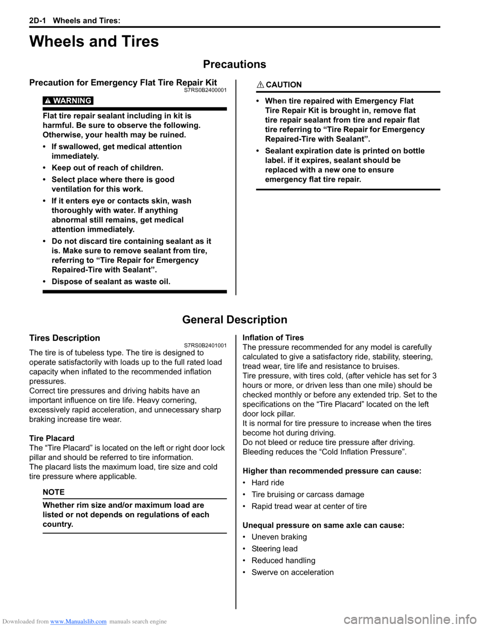
Precaution for Emergency Flat Tire Repair KitS7RS0B2400001
WARNING!
Flat tire repair sealant including in kit is
harmful. Be sure to observe the following.
Otherwise, your health may be ruined.
• If swallowed, get medical attention immediately.
• Keep out of reach of children.
• Select place where there is good ventilation for this work.
• If it enters eye or contacts skin, wash thoroughly with water. If anything
abnormal still rema ins, get medical
attention immediately.
• Do not discard tire containing sealant as it is. Make sure to remove sealant from tire,
referring to “Tire Repair for Emergency
Repaired-Tire with Sealant”.
• Dispose of sealant as waste oil.
CAUTION!
• When tire repaired with Emergency Flat Tire Repair Kit is brought in, remove flat
tire repair sealant from tire and repair flat
tire referring to “Tire Repair for Emergency
Repaired-Tire with Sealant”.
• Sealant expiration date is printed on bottle label. if it expires, sealant should be
replaced with a new one to ensure
emergency flat tire repair.
General Description
Tires DescriptionS7RS0B2401001
The tire is of tubeless type. The tire is designed to
operate satisfactorily with loads up to the full rated load
capacity when inflated to the recommended inflation
pressures.
Correct tire pressures and driving habits have an
important influence on tire life. Heavy cornering,
excessively rapid acceleration, and unnecessary sharp
braking increase tire wear.
Tire Placard
The “Tire Placard” is located on the left or right door lock
pillar and should be referred to tire information.
The placard lists the maximum load, tire size and cold
tire pressure where applicable.
NOTE
Whether rim size and/or maximum load are
listed or not depends on regulations of each
country.
Inflation of Tires
The pressure recommended for any model is carefully
calculated to give a satisfacto ry ride, stability, steering,
tread wear, tire life and resistance to bruises.
Tire pressure, with tires cold, (after vehicle has set for 3
hours or more, or driven less than one mile) should be
checked monthly or before any extended trip. Set to the
specifications on the “Tire Placard” located on the left
door lock pillar.
It is normal for tire pressure to increase when the tires
become hot during driving.
Do not bleed or reduce tire pressure after driving.
Bleeding reduces the “Cold Inflation Pressure”.
Higher than recommended pressure can cause:
• Hard ride
• Tire bruising or carcass damage
• Rapid tread wear at center of tire
Unequal pressure on same axle can cause:
• Uneven braking
• Steering lead
• Reduced handling
• Swerve on acceleration
Page 647 of 1496
Downloaded from www.Manualslib.com manuals search engine Automatic Transmission/Transaxle: 5A-3
General Description
A/T DescriptionS7RS0B5101001
This automatic transaxle is electronic control full automatic transaxle with forward 4-speed and reverse 1-speed.
The torque converter is a 3-element, 1-step and 2-phase type and is equipped with an automatically controlled lock-up
mechanism.
The gear change device consists of a ravigneau type planet ary gear unit, 3 multiple disc type clutches, 3 multiple disc
type brakes and 2 one-way clutches.
The hydraulic pressure control device consists of a valve body assembly, pressure control solenoid valve (linear
solenoid), 2 shift solenoid va lves, TCC pressure control solenoid valve (lin ear solenoid) and a timing solenoid valve.
Optimum line pressure complying with engine torque is produced by the pressure control solenoid valve in
dependence upon control signal from transmission control module (TCM). This makes it possible to control the line
pressure with high accuracy in accordance with the engine power and running conditions to achieve smooth shifting
characteristics and high efficiency.
A clutch-to-clutch control system is prov ided for shifting between 3rd gear and 4th gear. This clutch-to-clutch control
system is made to function optimally , so that hydraulic pressure controls such as shown below are conducted.
• When upshifting from 3rd gear to 4th gear, to adjust the drain hydraulic pressure at releasing the forward clutch, a
timing solenoid valve is used to switch a hydraulic passage with an orifice to another during shifting.
• When downshifting from 4th gear to 3rd gear, to adjust the line pressure applied to the forward clutch at engaging the forward clutch, a timing solenoid valve is used to s witch a hydraulic passage with an orifice to another during
shifting.
• When upshifting from 3rd gear to 4th gear with engine throttle opened, to optimize the line pressure applied to the forward clutch at releasing the forward clutch, the learning control is processed to compensate the switching timing
of the timing solenoid at every shifting.
• When downshifting from 4th gear to 3rd gear with engine throttle opened, to optimize the line pressure applied to
the forward clutch at engaging the forw ard clutch, the learning control is processed to compensate the line pressure
at every shifting.
Employing the ravigneau type planetary gear unit and this clutch-to-clutch control system greatly simplifies the
construction to make possible a lightweight and compact transaxle.
A line pressure learning control is conducted to provide opti mum shifting time at every upshifting with engine throttle
opened. If long upshifting time is detected, the subsequent line pressure applied during upshifting is intensified. On the
contrary, if short upshifting time is detected, the subs equent line pressure applied during upshifting is weakened.
Slip controlled lock-up function
Even at a lower speed than when the TCC gets engaged completely, control over the TCC pressure control solenoid
works to cause the TCC to slip (be engaged slightly), ther eby improving the transmission efficiency. While such slip
control is being executed, the oil pressure applied to the TCC is controlled by the TCC pressure control solenoid so
that the difference between the engine speed and the input shaft speed becomes close to the specified value.
Also, during deceleration, the TCC is made to slip (be enga ged slightly) to raise the engine speed and enlarge the fuel
cut operation range so that better fuel consumption is achieved.
Due to this reason, it is absolutely necessary for the automati c transmission to use ATF suitable for slip control. Use of
any fluid other than the specified ATF may cause j uddering or some other faulty condition to occur.
Page 649 of 1496
Downloaded from www.Manualslib.com manuals search engine Automatic Transmission/Transaxle: 5A-5
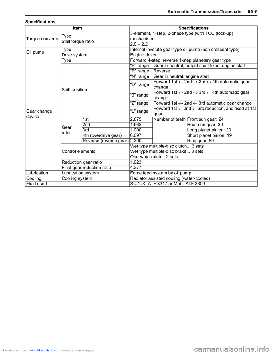
SpecificationsItem Specifications
Torque converter Ty p e
Stall torque ratio 3-element, 1-step, 2-phase type (with TCC (lock-up)
mechanism)
2.0 – 2.2
Oil pump Ty p e
Drive system Internal involute gear type oil pump (non crescent type)
Engine driven
Gear change
device Type Forward 4-step, reverse 1-step planetary gear type
Shift position
“P” range Gear in neutral, output shaft fixed, engine start
“R” range Reverse
“N” range Gear in neutral, engine start
“D” range
Forward 1st
↔ 2nd ↔ 3rd ↔ 4th automatic gear
change
“3” range Forward 1st
↔ 2nd ↔ 3rd ← 4th automatic gear
change
“2” range Forward 1st ↔ 2nd ← 3rd automatic gear change
“L” range Forward 1st
← 2nd ← 3rd reduction, and fixed at 1st
gear
Gear
ratio 1st 2.875 Number of teeth Front sun gear: 24
2nd 1.568 Rear sun gear: 30
3rd 1.000 Long planet pinion: 20
4th (overdrive gear) 0.697 Short planet pinion: 19
Reverse (reverse gear) 2.300 Ring gear: 69
Control elements Wet type multiple-disc clutch... 3 sets
Wet type multiple-d
isc brake... 3 sets
One-way clutch... 2 sets
Reduction gear ratio 1.023
Final gear reduction ratio 4.277
Lubrication Lubrication system Force feed system by oil pump
Cooling Cooling system Radiator assisted cooling (water-cooled)
Fluid used SUZUKI ATF 3317 or Mobil ATF 3309
Page 841 of 1496
Downloaded from www.Manualslib.com manuals search engine Manual Transmission/Transaxle: 5B-27
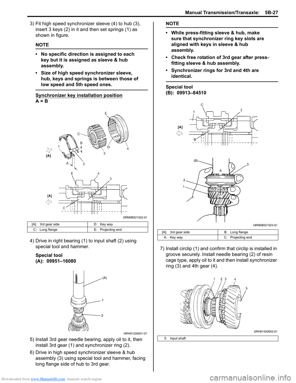
3) Fit high speed synchronizer sleeve (4) to hub (3), insert 3 keys (2) in it and then set springs (1) as
shown in figure.
NOTE
• No specific direction is assigned to each key but it is assigned as sleeve & hub
assembly.
• Size of high speed synchronizer sleeve, hub, keys and springs is between those of
low speed and 5th speed ones.
Synchronizer key in stallation position
A = B
4) Drive in right bearing (1) to input shaft (2) using special tool and hammer.
Special tool
(A): 09951–16080
5) Install 3rd gear needle bearing, apply oil to it, then install 3rd gear (1) and synchronizer ring (2).
6) Drive in high speed synchronizer sleeve & hub assembly (3) using special tool and hammer, facing
long flange side of hub to 3rd gear.
NOTE
• While press-fitting sleeve & hub, make sure that synchronizer ring key slots are
aligned with keys in sleeve & hub
assembly.
• Check free rotation of 3rd gear after press- fitting sleeve & hub assembly.
• Synchronizer rings for 3rd and 4th are identical.
Special tool
(B): 09913–84510
7) Install circlip (1) and confirm that circlip is installed in
groove securely. Install needle bearing (2) of resin
cage type, apply oil to it and then install synchronizer
ring (3) and 4th gear (4).
[A]: 3rd gear side D: Key way
C: Long flange E: Projecting end
I3RM0B521022-01
(A)
1
2
I4RH01520031-01
[A]: 3rd gear side B: Long flange
A: Key way C: Projecting end
5. Input shaft
I3RM0B521023-01
I2RH01520052-01
Page 853 of 1496

Downloaded from www.Manualslib.com manuals search engine Clutch: 5C-1
Transmission / Transaxle
Clutch
General Description
Clutch ConstructionS7RS0B5301001
The clutch is a diaphragm spring clutch of a dry single disc type. The diaphragm spring is of a tapering-finger type,
which is a solid ring in the outer diameter part, with a series of tapered fingers pointing inward.
The disc, carrying four torsional coil springs, is positione d on the transaxle input shaft with an involute spline fit.
The clutch cover is secured to the flywheel, and carries the diaphragm spring in such a way that the peripheral edge
part of the spring pushes on the pressure plate against the flywheel (with the disc in between), when the clutch release
bearing is held back. This is the engaged condition of the clutch.
Depressing the clutch pedal c auses the release bearing to advance and pushes on the tips of the tapered fingers of
the diaphragm spring. When this happens, the diaphragm sp ring pulls the pressure plate away from the flywheel,
thereby interrupting the flow of drive from flywheel through clutch disc to transaxle input shaft. Clutch fluid is supplied
from brake fluid reservoir. Clutch fluid level can be checked by brake fluid level of brake fluid reservoir.
[A]: For petrol engine model2. Flywheel5. Clutch cover 8. Input shaft bearing
[B]: For diesel engine model 3. Clutch disc6. Diaphragm spring 9. Input shaft
1. Crankshaft 4. Pressure plate7. Release bearing 10. Release shaft
I4RS0A530001-01
Page 949 of 1496
Downloaded from www.Manualslib.com manuals search engine Air Conditioning System: Manual Type 7B-1
HVAC
Air Conditioning System
Manual Type
Precautions
A/C System CautionS7RS0B7210001
CAUTION!
• The air conditioning system of this vehicle uses refrigerant HFC-134a (R-134a).
None of refrigerant, compressor oil and component parts is interchangeable between two types of
A/C: one using refrigerant HFC-134a (R-134a) and the other using refrigerant CFC-12 (R-12).
Be sure to check which refrigerant is used be fore any service work including inspection and
maintenance. For identification between these two types, refer to “Refrigerant Type Identification”.
When replenishing or changing refrigerant and comp ressor oil and when replacing parts, make sure
that the material or the part to be used is appropriate to the A/C installed in the vehicle being
serviced.
Use of incorrect one will result in leakage of refrigerant, damage in parts or other faulty condition.
• When servicing the compressor, keep dirt or foreign material away from getting on or into the compressor parts and system. Clean tools and a clean work area are important for proper service.
The compressor connection and the outside of the compressor should be cleaned before any “On
vehicle” repair or before removal of the compressor. The parts must be kept clean at all times and
any parts to be reassembled should be cleaned with trichloromethane, naphtha, kerosene or
equivalent solvent and dried with dry air. Use only lint free cloths to wipe parts.
• When compressor is removed from the vehicle for servicing, the oil remaining in the compressor
should be discarded and new refrigerant oil added to the compressor.
Minor repair procedures may be done on the vehicle without discharging the system. Major repair
procedures require that the system be discharged of refrigerant.
Precautions on Servicing A/C SystemS7RS0B7210002
WARNING!
Should refrigerant HFC-134a (R-134a) is exposed to your eye(s), consult a doctor immediately.
• Do not use your hand to rub affected eye(s). Instead, use fresh cold water to splash it over affected area to thus gradually raise its temperature above the freezing point.
• Obtain proper treatment as soon as possible from a doctor or eye specialist. Should liquid refrigerant HFC-134a (R-134a) is exposed to your skin, such affected part should be treated in the
same manner as when skin is frostbitten or frozen.
Handling Refrigerant HFC-134a (R-134a)
• Always wear goggles to protect your eyes.
• Avoid direct contact to liquid refrigerant.
• Do not heat refrigerant container higher than 40 °C (104 ° F).
• Do not discharge refrigerant into atmosphere.
• Do not expose bright metals to liquid refrigerant. Refrig erant combined with moisture is corrosive and tarnishes
surfaces of bright metals including chrome.
Page 950 of 1496
Downloaded from www.Manualslib.com manuals search engine 7B-2 Air Conditioning System: Manual Type
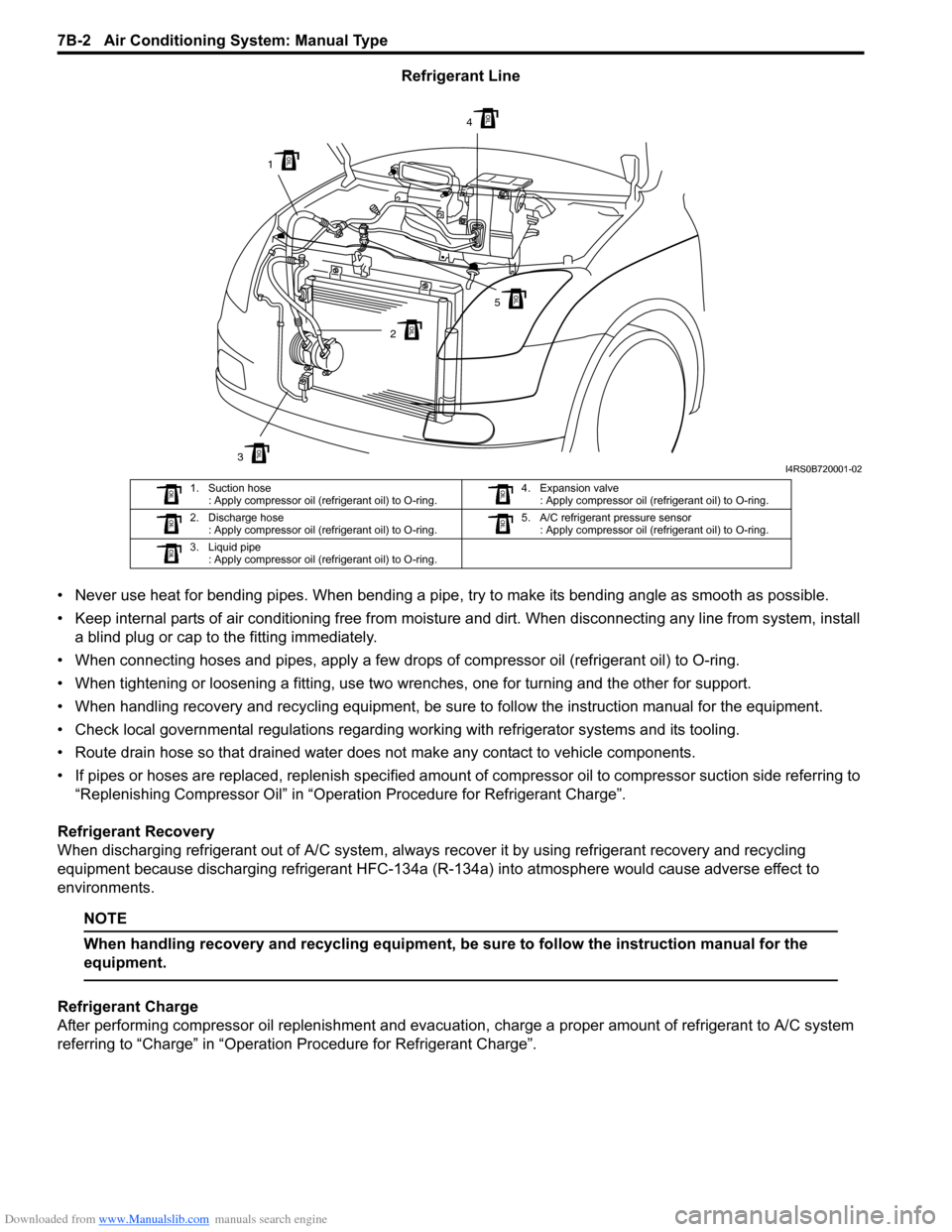
Refrigerant Line
• Never use heat for bending pipes. When bending a pipe , try to make its bending angle as smooth as possible.
• Keep internal parts of air conditioning free from moistu re and dirt. When disconnecting any line from system, install
a blind plug or cap to the fitting immediately.
• When connecting hoses and pipes, apply a few drops of compressor oil (refrigerant oil) to O-ring.
• When tightening or loosening a fitting, use two wrenches, one for turning and the other for support.
• When handling recovery and recycling equipment, be sure to follow the instruction manual for the equipment.
• Check local governmental regulations regarding working with refrigerator systems and its tooling.
• Route drain hose so that drained water does not make any contact to vehicle components.
• If pipes or hoses are replaced, replenish specified amount of compressor oil to compre ssor suction side referring to
“Replenishing Compressor Oil” in “Operation Procedure for Refrigerant Charge”.
Refrigerant Recovery
When discharging refrigerant out of A/C system, always recover it by using refrigerant recovery and recycling
equipment because discharging refrigerant HFC-134a (R-1 34a) into atmosphere would cause adverse effect to
environments.
NOTE
When handling recovery and recycling equipment, be sure to follow the instruction manual for the
equipment.
Refrigerant Charge
After performing compressor oil replenishment and evacuat ion, charge a proper amount of refrigerant to A/C system
referring to “Charge” in “Operation Procedure for Refrigerant Charge”.
3
1
2
4
5
I4RS0B720001-02
1. Suction hose : Apply compressor oil (refrigerant oil) to O-ring. 4. Expansion valve
: Apply compressor oil (refrigerant oil) to O-ring.
2. Discharge hose : Apply compressor oil (refrigerant oil) to O-ring. 5. A/C refrigerant pressure sensor
: Apply compressor oil (refrigerant oil) to O-ring.
3. Liquid pipe : Apply compressor oil (refrigerant oil) to O-ring.